Advertisement
Quick Links
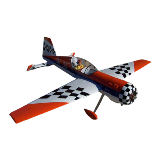
37.5% YAK 54 Assembly Manual
For assistance contact :
Aviation Models
25022 104th Ave SE, Suite E
Kent, WA 98030
Product Information:
Ordering Hotline:
Copyright © 2005 by Aviation Models, Inc. All rights reserved.
please report errors to sales@toc1.com
Aviation Models
Second edition rev. 5.12.28
1-253-332-0786
1-866-877-8621
1
Advertisement

Related Manuals for Aviation Models 37.5% Yak 54


Summary of Contents for Aviation Models 37.5% Yak 54
- Page 1 For assistance contact : Aviation Models 25022 104th Ave SE, Suite E Kent, WA 98030 Product Information: 1-253-332-0786 Ordering Hotline: 1-866-877-8621 Copyright © 2005 by Aviation Models, Inc. All rights reserved. Second edition rev. 5.12.28 please report errors to sales@toc1.com...
-
Page 2: Warranty Information
Warranty Information: Aviation Models, Inc. guarantees this kit to be free of defects in both material and workmanship at the time of purchase. This warranty does not cover any compo- nents damaged by use or modification. In no case shall Aviation Models, Inc. li- ability exceed the original cost of the purchased kit . - Page 3 Product Enquiry telephone number, or send an email to sales@toc1.com. Aviation Models guarantees this kit to be free of defects at the time of pur- chase. This warranty does not cover any components damaged by use or modification.
- Page 4 Table of Contents Page Subject Open and inspect everything Using this manual General Acknowledgments Installing Servos in the Wing Hinge the control surfaces 11 Pushrods 13 Install the main landing gear & Wheel Pants 16 Install the elevator servos 17 Rudder Installation 19 Tailwheel Assembly 20 Mount the rudder servo and linkage 20 Mount the horizontal stabilizers...
-
Page 5: Using This Manual
37.5% Yak 54 Assembly Manual Step 1. Open and inspect everything This section should be fairly self explanatory. In the large box you should have a fuselage with hatch., wing tube and dual stab tubes, the elevator/stab assemblies, the rudder, cowl, wheel pants, canopy, and a package with the landing gear, tail wheel bracket and miscellaneous nuts and bolts. - Page 6 Known issues and improvements There are a few areas where, at this unassembled stage, you can improve the final results of your assembly project. There are many items that cannot be addressed on the assembly line due to cost and possibly because not every improvement would be welcomed by every builder.
- Page 7 Installing Servos in Wings and Hinging Ailerons Locate the servo bay holes and cut the covering back. Use your covering iron and tack the cover- ing around the edges. Install the servo with four servo screws. 3. Locate the aluminum arm pro- vided in your hardware package.
- Page 8 Using a 2mm drill bit, drill four holes through the servo wheel. (You may also want to purchase some metal after-market servo wheels or arms for added strength. If after-market arms are used, they should be 1-1/2" long). Once the four holes are drilled, install the metal arm to the wheel using four 2x10mm bolts.
- Page 9 With the servo and arm installed, you can now start to measure the length of your pushrods. You can use whatever device you like for a control arm. You can drill through the moving surface and thread a bolt through, use a control horn, or a surface mount arm.
- Page 10 Once you are certain that they all go together smoothly, take one surface and remove the hinges. If you have a needle oiler, place 1 or 2 drops of oil into the hinge and work it back and forth. It’s also a good idea to put some lite oil (like WD40) on a rag, and to wipe the edges of the hinging surfaces with this rag.
- Page 11 Repeat this on both eleva- tors and both ailerons. For the rudder you may wish to wait until later to do the final installation of the rudder, it makes it easier to handle the airplane. To make the rudder removable, it is possible to remove the hinge pin from each hinge (grind off the recessed end and push the pivot out) and one or two pieces of wire as the pivot on all the hinges.
- Page 12 Remove the servo arm from the servo and thread the ball link onto the pushrod. Repeat this process for each of your servos – on each con- trol surface. Once you have all the servos mounted, it is a good idea to use a matchbox or other equalizing device, so that there is no binding in the servos.
- Page 13 Installing the Landing Gear Locate the landing gear pro- vided with the plane. Use the four 1/4x20 bolts pro- vided to mount the gear to the gear plate. Back the bolt from the inside with the four lock nuts provided as well. The bolts come through the canister tunnel.
- Page 14 Align the wheel pant and tape it into place. Then hold the wheel pant and drill the center hole through the landing gear. Take a smaller drill bit and drill through the holes in the landing gear. Then place blind nuts on the inside of the wheel pant.
- Page 15 Insert the axel through the wheel pant with the wheel inside the pant and tighten the nut on the inside of the wheel pant. Use the provided wheel collars to secure the wheel pant. Use the provided bolts to secure the wheel pant into place.
- Page 16 Installing Servos in Horizontal Stabilizer Mount the servo in the servo bay and install the arm onto the servo. You can now start to measure the length of your pushrods. Drilling holes for the control horns: Follow the same procedure as for the ailerons to mount your Eleva- tor control horns.
- Page 17 After your control rod is properly installed into your control sur- face, connect the rod to both the ball link and the clevis. Make sure the arm is 90 degrees to the horn. Stab servo, servo arm, and ele- vator control horn. The same steps apply to the elevator as with the ailerons.
- Page 18 Place hinges into the groove and probe them in and out several times to ensure that the glue has thoroughly covered the hinge. Before glue dries, insert hinge rod through hole in top of rudder, and guide it through the hinges, attaching the non-glued hinge half, and lining the hinges up on a straight line.
- Page 19 Tail Wheel Installation: Install your preferred tail wheel to the hard wood at the rear section of the fuselage. Here is an example of our installa- tion. Here is another picture of the tail wheel installation. Rudder Cable: T a k e a straight edge and mark where the rudder cable will touch the fuse side.
- Page 20 Mount your servos in the p r o- vided slots. Pre-drill the servo mounting screws and fasten servos. Rudder servo installation: The torque of your servos and your flying style will be deter- mining factors of how many ser- vos you will need. If you decide to run more than two, simply extend the mount and run them inline, ganging them together.
- Page 21 The next step is to mark the center of the firewall. will need to offset engine center the crank where it exits the cowl. Here is an example of what the firewall should look like when m o u n t i n g a 3W 150 engine.
- Page 22 Here is a picture of a 3w 150 mounted to the firewall. Throttle servo mount: Assemble the provided laser cut servo box and mount the servo to it. Position the servo mount on the motor box so that there is alignment for di- rect linkage to the carburetor.
- Page 23 Cowl Installation: Once the engine is mounted its time to start cutting out the cowl to clear the mufflers and also al- low for cooling. Make sure you have plenty of room around the pipes so vibration will not cause any cracks in the cowl.
-
Page 24: Control Throws
provided bolts fasten the canopy to the plane. A small piece of silicone fuel tubing slid over the bolt will keep them from vibrating out. Center of Gravity: Assemble the entire plane as though you were about to fly. Set the balance point of your aircraft at 9.63" back from the leading edge of the wing. - Page 25 If you are in doubt about your skills, ask a skilled aerobatic pilot to help you with a trainer cord. Thanks for Purchasing our 37.5% Yak 54. We hope it provides you with many hours of enjoyment. Good luck! Sammy...
Need help?
Do you have a question about the 37.5% Yak 54 and is the answer not in the manual?
Questions and answers