Table of Contents
Advertisement
Quick Links
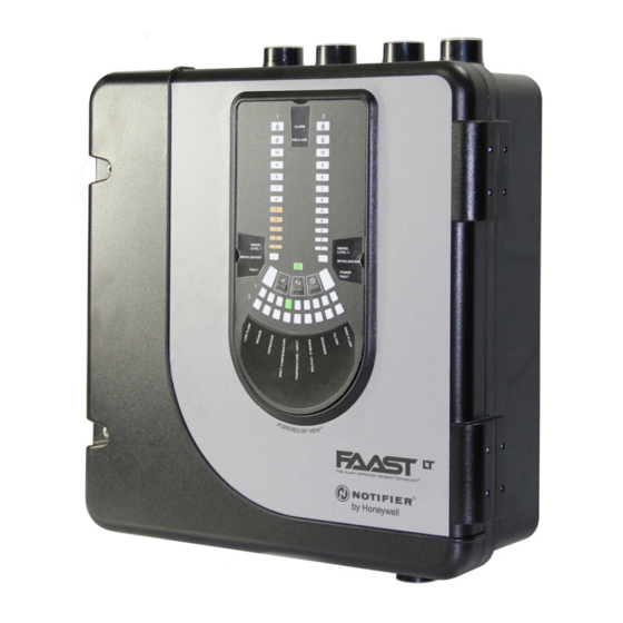
DESCRIPTION
The LT NFXI-ASD Series is part of the Fire Alarm Aspiration
Sensing Technology
(FAAST) family. FAAST is an advanced
®
fire detection system for use where early warning and very early
warning are a requirement. The system continuously draws air
from the controlled environment through a series of sampling holes
to monitor the environment for smoke particulate.
The NFXI-ASD is the addressable version of the FAAST LT range,
communicating with the CIE (Fire Panel) via a proprietary loop
protocol. It is available in 3 different models:
NFXI-ASD11 - Has single channel capability with one laser smoke
sensor.
NFXI-ASD12 - Has single channel capability with two laser smoke
sensors in a common chamber for coincidence
detection.
NFXI-ASD22 - Has two channel capability with two laser smoke
sensors in separate chambers. (one sensor for
each channel).
This guide provides information for mounting and basic installation
using the unit's default factory settings. For more advanced information
please see the FAAST LT Advanced Setup and Control Guide.
SPECIFICATIONS
Electrical Characteristics
Voltage Range:
Supply Current:
1 Channel:
2 Channel:
Communication Loop Supply Voltage: 15 – 29 VDC (Loop current ≤
Communication Loop Standby Current: @ 24V: 900 µA max. (poll once
Module Isolator Characteristics
Maximum rated switching current
(under short circuit, Is max):
Maximum leakage current (IL max)
with the switch open (isolated state):
Maximum series impedance with
the switch closed (Zc max):
N200-102-00
FIRE ALARM ASPIRATION SENSING TECHNOLOGY
QUICK INSTALLATION GUIDE ADDRESSABLE FAAST LT
MODELS NFXI-ASD11, NFXI-ASD12, NFXI-ASD22
18.5 - 31.5 VDC
170mA (typical); 360mA (max) @
24 VDC 25
C (excluding sounders)
o
270mA (typical); 570mA (max) @
24 VDC 25
C (excluding sounders)
o
900mA)
every 5s)
0.9A @ ≤ 29V
15mA
190 m ohm at 15Vdc; 1A
356 mm
Figure 1: Dimensions and Knock-Outs
Power Reset:
Configurable Input: Activation Time:
Relay Contact Ratings:
Environmental Ratings
Temperature:
Relative Humidity:
IP Rating:
Mechanical
Exterior Dimensions:
Wiring:
Maximum Single Pipe Length
Maximum Number of Holes
Pipe Spec (EN54-20 Compliance):
Outside Pipe Diameter:
Shipping Weight:
PARTS LIST
Description
FAAST LT unit
Mounting bracket
3-pin Terminal block
4-pin Terminal block
2-pin Terminal block
47 k-ohm EOL Resistor
USB Cable
Front Panel Labelling Pack
Installation Kit CD
Quick Installation Guide
Aspirating Smoke Detectors supplied and installed within the
EU must conform to the EU Construction Products Directive
(89/106/EEC) and the related European Product Standard EN
54-20. FAAST LT has been tested and certified to ensure that it
conforms to the necessary Standards, but strict adherence to this
instruction guide is advised to ensure that the installation meets
the requirements of the CPD Directive.
1
E N G L I S H
0.5s
2s (min)
2.0 A @ 30 VDC, 0.5A @ 30 VAC
-10°C to 55°C
10% to 93% (non-condensing)
65
See Figure 1
0.5 mm² to 2 mm² max
See Table 1A
See Table 1A
to EN 61386
(Crush 1, Impact 1, Temp 31)
25mm (nom) or 27mm (nom)
6.5kg (inc sensors)
Quantity
1
1
6
1
3
2
1
1
1
1
Important Note
®
44 mm
56 mm
135 mm
I56-3947-200
Advertisement
Table of Contents

Related Manuals for Honeywell Notifier FAAST LT NFXI-ASD Series


Summary of Contents for Honeywell Notifier FAAST LT NFXI-ASD Series
- Page 1 E N G L I S H FIRE ALARM ASPIRATION SENSING TECHNOLOGY ® QUICK INSTALLATION GUIDE ADDRESSABLE FAAST LT MODELS NFXI-ASD11, NFXI-ASD12, NFXI-ASD22 44 mm 56 mm DESCRIPTION 356 mm 135 mm The LT NFXI-ASD Series is part of the Fire Alarm Aspiration Sensing Technology (FAAST) family.
-
Page 2: Physical Installation
This equipment and all associated pipe work must be installed in accordance with all relevant codes and regulations. PHYSICAL INSTALLATION Front Panel Labels Figure 4: How to Knock Out Cable The LT NFXI-ASD is shipped without the front panel labels fixed in Gland Holes place. -
Page 3: Pipe Installation
Figure 7: Sequence (1 to 9) to Mount the Detector on the Bracket Pipe Hole Configuration Figure 8 below shows the pipe holes available on the unit. Each unit has 2 pipe holes per channel (so if installing a 1 channel unit, 99 mm holes 3 and 4 do not function). -
Page 4: Wiring Installation
Exhaust Pipe SAMPLING AREA SAMPLING AREA WIRING INSTALLATION Power, Alarm and Control Connections CHANNEL 1 FILTER CHANNEL 2 FILTER Note 1: All wiring should comply with local requirements and regulations. Note 2: Loop wiring must observe the EARTH BAR recommendations of the panel manufacturer MOUNT EARTH BAR (OPTIONAL) -
Page 5: Setting The Addresses
Table 2: Wiring Terminal Designations Address 1; in 2 channel units (or when two sensors are fitted) the second device is set to Address 2. (Note - Terminals marked CH2 will only be available on 2 channel models) Any sensor address may be used except 0, whilst respecting the panel’s rules on co-operative Function Multi-Sensing* (see below) between the VIEW™... -
Page 6: External Reset
2. Check the voltage at the connector. Make sure it is within the required voltage range. 3. If the voltage is within the specified range, connect the power connector to the unit. ALARM 4. Close and secure the housing door; verify the fan starts up and PREALARM air flows out of the exhaust port. - Page 7 Table 4: Front Panel Indicators and Fault Descriptions INDICATOR ACTION WARNING OR TROUBLE COMMENT / ACTION CHANNEL 1/2 ALARM ON Red Channel is in alarm (relay is Default setting (Set by panel) set ON with no delay) 1 BLINK Green When sensor is polled Not when in alarm (Polled by panel)
- Page 8 PREALARM SMOKE Table 5: Front Panel Buttons LEVEL 2 INITIALIZATION BUTTON NORMAL Mode MAINTENANCE Mode RESET When pressed for 2 s, starts PASSWORD When pressed for 2 s latched alarms, faults and POWER PROCEDURE to enter Maintenance sounders (relays) are reset. Alarm controlled by panel. If FAULT mode.
-
Page 9: Laser Safety Information
PipeIQ™LT QUICK START INSTRUCTIONS Either replace the filter assembly or carefully brush off the accumulated dust. Overview of PipeIQLT Note: If replacing the filter, remove the foam gasket from the old The PipeIQLT software program is a convenient and powerful filter and place onto the new filter. - Page 10 Quitting Exiting the program closes the application completely. To quit the PipeIQLT application, click X in the upper-right corner of the window. Or click Exit from the File menu. PipeIQLT can be uninstalled from the computer in the normal way for your operating system.
Need help?
Do you have a question about the Notifier FAAST LT NFXI-ASD Series and is the answer not in the manual?
Questions and answers
Boru tesisat uçları kapalimi yada açık mı olacak yardımlarınızı bekliyoruz teşekkürler