
Subscribe to Our Youtube Channel
Related Manuals for ALMAC MULTI-LOADER 2.5


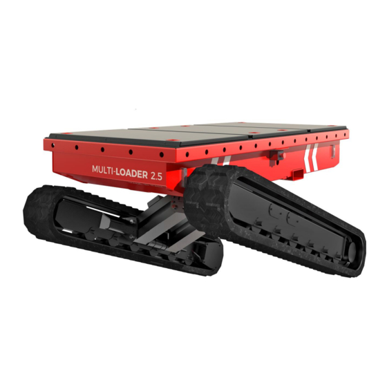
Summary of Contents for ALMAC MULTI-LOADER 2.5
- Page 1 Translation of original instructions Prior to commissioning the machine carefully read this Use and Maintenance Manual Note: table of contents at the end of the manual Edition Date 22/03/2017...
-
Page 2: General Information
• Report register 1.2 Details of Manual • Instruction manual • Model: MULTI-LOADER 2.5 Note: Some of the photos and illustrations may not refer specifically to the version of the machine in your possession, but provide indications concerning the purpose for which they have been included. - Page 3 ALMAC s.r.l. hereby declares that the information in this manual was congruent with the technical and safety specifications of the machine to which the manual refers.
-
Page 4: Identification Data
ALMAC s.r.l. PAGE 1.5 Identification data. The machine named MULTI-LOADER 2.5 is defined according to the current technical standards such as: Identification plate In any case, refer to the data on the identification plate for an exact identification. - Page 5 ALMAC s.r.l. PAGE 1.6 Performance Below are the configurations that can be assumed in the work and transportation conditions: Characteristic dimensions Machine length 2.40 Maximum width 1.64 Widened track Maximum width 1.46 Narrow track Height of crawler Width of crawler Load platform minimum height 1.07...
- Page 6 ALMAC s.r.l. PAGE Technical data Maximum capacity 2500 Hydraulic side-shift pressure Maximum capacity 2500 Hydraulic pressure traslation Oil tank capacity Climb angle ° Maximum side slope of the terrain ° Maximum longitudinal slope of the terrain ° 20 / 15...
- Page 7 ALMAC s.r.l. PAGE Standard equipment Optional equipment Electric motor 220V/2.2kw Proportional electrohydraulic controls or 110V/1.9kw Lead Crystal battery pack 180Ah/48V Electric motor 48V – 3000W Automatic accelerator Remote control CANBUS display to manage working hours and alarms Dual speed gear motors...
-
Page 8: Warranty
Work under guarantee must only be performed by workshops authorised by ALMAC S.r.l. and only when the Customer is up to date with the payments. The Customer will not be entitled to work under guarantee unless he consigns the equipment for repair within 30 days from the date of the first complaint, to be made in writing. - Page 9 PAGE 1.8.1 Request for interventions during warranty period and formalities ALMAC S.r.l. must be notified of requests for spare parts or technical interventions under guarantee as soon as a defect is discovered. Always indicate the type of machine and its serial number when requesting spare parts under guarantee or technical interventions under guarantee.
- Page 10 ALMAC s.r.l. PAGE 1.10 Use of the manual Note: Keep this manual in an accessible place known to all users (operators and maintenance workers). Note: This manual must be kept in a protected place inside the compartment provided on the work platform so that it can be easily accessed for consultation throughout the entire technical life of the machine.
- Page 11 ALMAC s.r.l. PAGE 1.11 Intended use and improper uses 1.11.1 Intended use The machine described in this manual is a machine designed to transport various materials and/or pieces of equipment. The maximum allowed capacity for this model is 2500 kg.
- Page 12 ALMAC s.r.l. PAGE 1.11.2 Improper uses Any other use not specifically indicated in 1.11.1 Intended use. • It is forbidden to operate the machine from the ground using the mobile push-button panel with an operator on the loading platform. 1.11.3...
-
Page 13: Safety Information
*The law that currently governs health control and surveillance of workers is the Provision of the State-Regions Permanent Conference of 16 March 2006. Note: ALMAC S.r.l. declines all liability for damage to persons, animals and things deriving from: • failure to comply with the safety regulations •... - Page 14 ALMAC s.r.l. PAGE 2.2 Warnings The following sign plates are affixed to the machine: • Identification • Instructions • Command/prohibition sign plates • Caution • Danger 2.2.1 Plates indicating instructions, obligations, dangers, prohibitions and warnings...
- Page 15 Note: The inclinations listed on the plate above refer to those LIMITS that cannot be exceeded with the machine. Almac s.r.l. has provided on the platform an electronic control system that limits translation of the machine upon...
- Page 16 ALMAC s.r.l. PAGE The plates are affixed to the machine for the purpose of helping the operator and/or warning him of the risks to which he may be exposed when he uses the machine. In no way does the information on the plates substitute this Manual, which is the only reference document containing complete information.
- Page 17 ALMAC s.r.l. PAGE 2.2.2 Meanings of the sign pictograms Warning / Danger. This symbol means that you must take care or that danger is present. Failure to comply with this alert indication could cause damage to the machine, the operator or exposed persons.
- Page 18 ALMAC s.r.l. PAGE 2.3 Provisions and prohibitions • Read this manual carefully before starting, using, servicing or performing other operations on the machine. • The machine must always be kept in perfect conditions by following the maintenance program described in the Maintenance Chapter.
- Page 19 ALMAC s.r.l. PAGE 2.4 Transport and loading You are advised to check the dimensional limits established for means of transport if the machine must be transported to its specific work site. The machine can be loaded onto the vehicle in two different ways:...
- Page 20 ALMAC s.r.l. PAGE 2) Lifting the machine by forklift using the relevant tubular elements. Attention: the maximum weight of the machine in the heaviest configuration is 1800 Kg Note: Once the machine is positioned on the vehicle, secure it by means of...
- Page 21 ALMAC s.r.l. PAGE Warning: the chassis must be completely lowered (chassis wide) Attention: Do not excessively tighten the fixing straps to avoid damaging the structure.
- Page 22 ALMAC s.r.l. PAGE 2.5 Checks on the machine before each use • Make sure that there is no hydraulic oil leaking from the hoses and from the other components (cylinders, distributors, fittings, etc.). • Check that there are no cut or worn electrical cables and that the connectors are correctly secured.
- Page 23 ALMAC s.r.l. PAGE Type of terrain, geomorphological Permitted surface pressure characteristics Loose non-compact soil In general, not solid; requirement for particular measures Mixed, compact soil, sand and gravel 2.0 kg/cm² 0.2 N/mm² Semi-solid cohesive soil 1.0 Kg/cm² 0.1 N/mm² Solid cohesive soil 2.0 Kg/cm²...
- Page 24 ALMAC s.r.l. PAGE damage the tracks. ALWAYS PROCEED WITH THE TRACK SHOES RESTING ON THE SAME HORIZONTAL PLANE. • Driving over an obstacle creates a gap between the bearing rollers and track, which could consequently slip out of its housing.
- Page 25 ALMAC s.r.l. PAGE NO ICE! NO SAND! NO DUST OR SMOOTH SURFACES! Attention: during movement with ELECTRICAL POWER, be careful of the connection cable in order to avoid dangerously crushing the cable itself!
- Page 26 ALMAC s.r.l. PAGE 2.8 Safety checks on the operation of the machine, to be performed before The instructions given below must be followed. • Position the machine with the frame inclined to the horizontal with a value greater than 0.5° on the side. Activate the automatic levelling control (Automatic levelling), make sure that the system automatically keeps the frame horizontal.
- Page 27 Only perform the MAINTENANCE and ADJUSTMENT operations described in this Manual. Contact the ALMAC S.r.l. assistance service only, if other operations are required (e.g. if faults occur). All MAINTENANCE work must be performed in compliance with the laws in force governing safety and protection of the environment.
-
Page 28: Personal Protective Equipment
ALMAC s.r.l. PAGE • Make sure there are no fluids under pressure before disassembling unions or pipes: oil spattering out under pressure can cause serious injuries. Immediately call a physician if injuries occur or the fluid from pipes is accidentally ingested. Remember that fluid seeping from a very tiny hole can be almost invisible but possess sufficient force to penetrate under the skin. - Page 29 The design, weight and dimensions were devised considering safety aspects, especially spaces and insulations. The use of batteries not approved by Almac S.r.l may detract from the performance and reliability of the machine. In the event of significant differences, problems of electrical insulation of the machine can be highlighted with all the associated risks.
- Page 30 ALMAC s.r.l. PAGE 2.13 Batteries Maintenance and Verification 2.13.1 Clothing Always wear a visor or goggles when operating on the batteries. Wear plastic gloves, an apron or overall to protect your clothes; remove bracelets, rings or other metal objects that could cause short involuntary circuits.
- Page 31 ALMAC s.r.l. PAGE 2.13.3 Replacement of individual batteries a. Disconnect the power supply of the machine via the battery switch; b. Remove the two planes A and B c. Disconnect the GND battery negative pole (see photo below) taking care to keep the disconnected part well insulated, protecting it adequately.
- Page 32 ALMAC s.r.l. PAGE d. Disconnect the +48V battery positive pole (see photo below) taking care to keep the disconnected part well insulated, protecting it adequately. By way of example only, achieve this with insulating tape or with plastic casing. e. Once all the operations have been performed up to point d, each individual battery (6V) can be replaced by removing the mechanical fixing (See photo indication).
- Page 33 ALMAC s.r.l. PAGE This can also be achieved by disconnecting the poles (as shown in the figure below) having also in this case protected and isolated them. 2.14 Battery status maintenance The machine stored without recharging of the batteries can remain for up to...
- Page 34 ALMAC s.r.l. PAGE Attention: Always wear a visor or goggles when operating on the battery. Wear plastic gloves, an apron or overall to protect your clothes. remove bracelets, rings or other metal objects that could cause short involuntary circuits. Carefully read the instructions for use and maintenance before carrying out any operation with the battery.
-
Page 35: Description Of The Machine
ALMAC s.r.l. PAGE 3 DESCRIPTION OF THE MACHINE 3.1 Structure of the equipment This section describes the main components of the machine and their functions. 1. Control push-button panel (console) 2. Control console emergency button 3. Remote control compartment 4. Remote control charge 5. - Page 36 ALMAC s.r.l. PAGE 7. Main hydraulic unit 8. Flashing light 9. Ground control panel emergency 10. Electronic control unit (ECU) button 11. Remote control unit 12. Remote control battery recharge compartment...
- Page 37 ALMAC s.r.l. PAGE 13. Remote control emergency cable 14. Battery disconnect switch connector 15. Emergency button right side 16. Emergency button left side 17. Hydraulic oil tank 18. Discharge filter 19. Intake filters (in the tank) 20. Oil tank refill cap...
- Page 38 ALMAC s.r.l. PAGE 21. Visual hydraulic oil level 22. Booster for translation speed management 23. Electric motor AC 110V or 220V 24. Electric motor DC 48V 25. Batteries 26. Battery charger...
- Page 39 ALMAC s.r.l. PAGE 27. Contactors group 28. Converter 220V/110V - 12V 29. Frame angle sensor 30. Rod angle sensor 31. Chassis angle sensor 32. Bi-levelling chassis 33. Attacchi rapidi...
-
Page 40: Control Stations
ALMAC s.r.l. PAGE 3.2 Control stations 3.2.1 Mobile control push-button panel (console) The machine is equipped with a mobile control push-button panel (console) that allows normal operation with the operator on the ground. In the event of an emergency, the push-button panel can also be connected to the supplied cable by tightening the appropriate ring indicated. - Page 41 ALMAC s.r.l. PAGE...
- Page 42 ALMAC s.r.l. PAGE No. Identification Function and Description of the function Status ENGINE IGNITION AND AUTOMATIC LEVELLING Ignition of 1. Press the button to access the machine and radio control (after releasing the console emergency mushroom); 2. Press the button again to activate...
-
Page 43: Drive Mode
ALMAC s.r.l. PAGE No. Identification Function and Description of the function Status height of 0.75 meters. Automatic Automatic levelling of the machine Button (AUTOMATIC levelling on all the axes. LEVELLING) DRIVING MODE SELECTOR Position Standard operation traction DRIVE MODE FORWARD/REVERSE enabled using 2 joysticks. - Page 44 ALMAC s.r.l. PAGE No. Identification Function and Description of the function Status Auxiliary connector for places where radio frequencies cannot be used. Connector Battery necessary for console power supply. Battery Cable The cable is used in this particular condition: - Use of radio remote control via cable (radio bridge by- pass).
-
Page 45: Emergency Stop
ALMAC s.r.l. PAGE 3.2.3 Ground controls The platform features a control console located on the chassis at the back of the machine. These commands are for the operator in case of emergency situations (red mushroom button). Attention: The key must always be available. - Page 46 ALMAC s.r.l. PAGE Attention: the 20A recharge is only necessary if a current is available from the panel of max 10Aac, but, mainly, use the 40A recharge to maintain the optimal state of the batteries. 3.3 Operating safety devices Attention: Periodically verify that the safety devices are operating correctly.
- Page 47 ALMAC s.r.l. PAGE 3.3.2 Chassis tilt control device A Can Bus angle sensor is fixed to the machine's chassis which constantly transmits the measured inclination to the electronic control unit. The angle sensor is redundant (thus composed of two distinct sensors) and the Y axis of machine inclination (longitudinal) is monitored.
- Page 48 1. Maximum system pressure valve : set to 220 bar; 2. Maximum system pressure valve : set to 220 bar. Warning: modifications to the positions of the maximum pressure valves without authorization from ALMAC S.r.l. will void the warranty and any claims made by the customer.
- Page 49 ALMAC s.r.l. PAGE 3.4.2 Hydraulic block safety devices The hydraulic block features three solenoid valves with possible manual by-pass. These solenoid valves, indicated with 1-2-3, are part of the safety system of the machine and must never be operated manually.
- Page 50 ALMAC s.r.l. PAGE If there is an accidental failure of one of the hydraulic pipes that feed the levelling cylinders of the tracked chassis, with consequent sudden variation of the roadway and the inclination, appropriate BALANCING VALVES prevent sudden movement of the chassis.
- Page 51 ALMAC s.r.l. PAGE 3.5 Blackout safety devices 3.5.1 External power source 230V or 110V On the machine there is a plug to power the AC electric motor or the battery chargers to recharge the traction batteries. For safety reasons, a device is installed so as to cut-out the electricity supply in case of over-voltage and "differential circuit breaker"...
- Page 52 ALMAC s.r.l. PAGE 3.5.2 12V-48V system On the right side of the machine is the "battery disconnector" (3) that physically disconnects the 48V power line coming from the battery and supplies the various users, and the 12V line of electronic power supply and utilities.
- Page 53 ALMAC s.r.l. PAGE 3.6 Platform operation devices which are not part of the safety system On both connecting rod assemblies (right and left) connecting the tracked chassis and the central frame, there are two Can Bus angle sensors. The angle sensors are redundant (thus consisting of two separate sensors) and monitor the X inclination axis of the respective connecting rod.
-
Page 54: Preliminary Operations
ALMAC s.r.l. PAGE 4 Instructions for use 4.1 Preliminary operations 4.1.1 Suitability of the soil To assess whether the ground is fit to bear the machine, it is extremely important to ensure that the ground surface does not allow the machine to slip once it has been stopped for work. - Page 55 ALMAC s.r.l. PAGE 4.2 Machine operation 4.2.1 Powering of the machine. To turn the machine on, it is necessary to reset all the emergency mushroom buttons (side, ground panel and console) and to turn the key selector located in the ground controls to position 1;...
- Page 56 ALMAC s.r.l. PAGE ATTENTION! If the RED led (7) lights up when the machine is switched on, it means that an active command is already present at start-up (Joystick contact or movement selector jammed). Once ignition is completed it is therefore possible to start the motor: •...
- Page 57 ALMAC s.r.l. PAGE 4.2.2 Travel controls The controls used for the movement of the platform are represented by 2 joysticks (9-10) located on the control panel. (see photo below). Each lever controls the respective track (right lever→right track, left lever→left track).
- Page 58 ALMAC s.r.l. PAGE Left turn Rotation on itself towards the right (counter-rotation) Rotation on itself towards the left (counter-rotation) ATTENTION: If you must drive up a slope, do not change direction when the ground changes from flat to sloping. If this is absolutely necessary, perform the manoeuvre gradually.
- Page 59 ALMAC s.r.l. PAGE 4.2.2.1 Standard travel mode With the selector (6) on the central position "DRIVE MODALITY", it is possible to carry out all the translation movements with independent tracks (see paragraph 4.2.1).
- Page 60 ALMAC s.r.l. PAGE 4.2.2.2 Easy-Drive System (ED-S) Moving the selector (6) on the push-button panel to the "ED-S" position activates a special function that allows you to control the rotation of the control stations, especially when operating on cultivated or grassy terrain, so that the tracks do not rip the cultivation during the manoeuvre.
- Page 61 ALMAC s.r.l. PAGE 4.2.2.3.1 Dynamic Levelling ON During translation the levelling is automatically performed to ensure the loading platform is always parallel to the ground in any translation mode. 4.2.2.3.2 Dynamic Levelling OFF During translation the loading platform remains fixed and is not self-levelling. If...
- Page 62 ALMAC s.r.l. PAGE 4.2.3 Machine levelling The machine is equipped with an automatic levelling system with hydraulic cylinders, to allow the machine to operate within the maximum inclination permitted, thus always keeping the loading platform horizontal with respect to the ground within a range of ± 0.5°, both longitudinally (longitudinal cylinder) and laterally (connecting rod cylinders).
- Page 63 ALMAC s.r.l. PAGE 4.2.3.1 Automatic levelling It is possible to activate automatic levelling by pressing the black button (5) located on the right side of the console. The system will bring the frame back to an inclination of less than 0.5°...
- Page 64 ALMAC s.r.l. PAGE 4.2.3.3 Dynamic Levelling during travel Thanks to this system the machine, during translation, remains constantly levelled. To activate this mode, it is necessary to turn the selector 8 of the push-button panel to the "DYNAMIC LEVELING ON" position and the selector 6 to the "DRIVE MODALITY"...
- Page 65 ALMAC s.r.l. PAGE 4.2.3.4 Dynamic Position System This selector allows you to choose between three different heights of the loading platform. During translation or automatic levelling, the machine will move and keep the selected configuration. HIGH Maintain maximum height of the platform from the ground...
- Page 66 ALMAC s.r.l. PAGE 4.3 Positioning of the load on the machine The machine has been designed and built for loading and moving various materials and/or equipment. The loading platform has dimensions of 1.11 meters x 2.40 meters, and has a maximum capacity of 2500 kg.
- Page 67 ALMAC s.r.l. PAGE A number of examples follow:...
- Page 68 ALMAC s.r.l. PAGE...
- Page 69 ALMAC s.r.l. PAGE...
- Page 70 ALMAC s.r.l. PAGE 4.4 Messages and alarms on the hour counter The hour counter located at the back, allows you to view the status of the machine. This display also shows any errors and/or alarms that may occur. E = operating hours with 220Vac electric motor e = operating hours with 48Vdc electric motor In the upper part the charge status of the 48V battery is shown.
- Page 71 ALMAC s.r.l. PAGE If there are no alarms at the moment but there were alarms previously (alarms caused by malfunctions that appear intermittently), the service symbol will appear on the display: The control unit can store up to 16 alarms which are shown by pressing the right button of the hour counter.
- Page 72 ALMAC s.r.l. PAGE The table below shows the list of alarm/error codes. CODE DESCRIPTION EPROM memory internal error CAN network communication error Frame angle sensor redundancy error Chassis angle sensor redundancy error No signal from the frame angle sensor 1...
- Page 73 ALMAC s.r.l. PAGE 4.5 Quick couplings (if any) On the right side of the machine are the quick couplings (2), they offer the availability to use any tool with hydraulic supply. To activate the operation it is necessary to move the AUX selector (1) towards the right (ON), in this way the quick couplings are activated, at the same time all the machine controls are enabled, including translation and self-levelling.
- Page 74 ALMAC s.r.l. PAGE 4.6 Stopping the machine 4.6.1 Normal stop During normal machine use, releasing the TRANSLATION joysticks (9 and 10) stops the movement. Each track installed has a braking system that prevents the machine from moving unless hydraulic pressure is exercised to disengage it.
- Page 75 ALMAC s.r.l. PAGE 4.6.2 Emergency stop In abnormal circumstances, or situations in which all machine movements must be stopped, the operator can IMMEDIATELY STOP all the machine functions by pressing the MUSHROOM-SHAPED button on the push-button, or the emergency button place on the GROUND CONTROLS (see figures below).
-
Page 76: Emergency Procedures
ALMAC s.r.l. PAGE 5 Emergency procedures 5.1 Reception problems with remote control If the radio control console does not work correctly, it is possible to use the cable supplied (1) to connect it to the machine using the connector (2). - Page 77 5.3 Emergency movements from hydraulic block Warning: this operation must be performed only by qualified technicians trained by Almac S.r.l. In the event that there is a malfunction of the control unit but it is possible to switch on the electric motor, the movements of the machine can then be performed directly from the hydraulic block.
-
Page 78: General Maintenance
ALMAC s.r.l. PAGE 6 Maintenance 6.1 General maintenance The main maintenance interventions and the frequencies with which they must be carried out are given in the chart below. 6.1.1 Ordinary maintenance schedule table The checks and maintenance operations must be performed as indicated in the table below. - Page 79 Note: All maintenance work that is not described in this manual must be authorised by the manufacturer and must be performed by authorised technicians. Attention: Do not use the machine if one of its mechanical or hydraulic elements or a control or safety device is faulty. Immediately notify Almac S.r.l.
-
Page 80: Visual Check
ALMAC s.r.l. PAGE 6.1.2 Checks before each use Prior to commissioning and before each use the machine must undergo the visual and functional checks given below. The instructions given below must be followed. VISUAL CHECK CHECK OPERATION • • Make sure that there is no hydraulic oil... -
Page 81: Maintenance: Details
ALMAC s.r.l. PAGE 6.2 Maintenance: Details The following points deal with the most significant specific cases 6.2.1 Checking and tightening screws, bolts, plug ring nuts The operation of the following components must be checked. If necessary, the parts must be tightened with the appropriate tools as indicated in the charts on the following pages. - Page 82 ALMAC s.r.l. PAGE 6.2.2 Visual and structural inspection Visually check the following points according to the schedule indicated in the general chart. Immediately inform a maintenance technician if faults are discovered. • Frame state; • State of the bi-levelling structure and of the tracked chassis;...
- Page 83 ALMAC s.r.l. PAGE 6.2.4 Checking the hydraulic tank oil level and topping up if necessary The hydraulic oil level is checked by means of a level indicator located directly on the tank. 6.2.5 Hydraulic reservoir oil change The hydraulic oil in the tank must be changed with the frequency indicated in the general chart.
- Page 84 ALMAC s.r.l. PAGE 6.2.6 Checking the operation of the maximum pressure valves With the frequency indicated in the general chart, check the operation of the maximum pressure valves of the distributor. To test them, connect two pressure gauges with a full scale of 250 bar to the pressure outlets supplied (4 and 5).
- Page 85 ALMAC s.r.l. PAGE The valves are calibrated during the testing phase performed by ALMAC S.r.l. and should not require further adjustment unless: • the hydraulic circuit is replaced; • the actual pressure relief valve is replaced. In these cases, the valve must be calibrated by SPECIALIST PERSONNEL according to the monitoring procedure described above.
- Page 86 ALMAC s.r.l. PAGE 6.2.7 Hydraulic filter replacement Replace the discharge filters of the hydraulic circuit at the frequencies indicated in the general chart. The hydraulic oil tank features: No.2 intake filters inside the tank (1) 1 discharge filter in the top part of the tank (2).
- Page 87 ALMAC s.r.l. PAGE 6.2.7.1 Suction filters replacement To replace the intake filters located inside the hydraulic tank, proceed as follows: 1) Remove the central filling platform; 2) Empty the hydraulic oil tank; 3) Unscrew the blocking screws (1) on the hydraulic tank lid and remove it from its housing;...
- Page 88 ONLY USE GENUINE SPARE PARTS when replacing the filters. Contact the ALMAC technical assistance service. Do not reuse used oil. Do not dispose of it in the environment. Used oil must...
- Page 89 ALMAC s.r.l. PAGE 6.2.8 Traction batteries (Type:Lead Crystal) 6.2.8.1 General warnings The battery is an essential component for machine operation. It is important to ensure that it remains in a good condition over time since this will lengthen its working life, limit any problems that may arise and reduce the running costs of the machine.
- Page 90 • PLACE BATTERIES AND ELECTRICAL APPLIANCES OUT OF THE REACH OF CHILDREN. 6.2.8.2 Maintenance The batteries chosen by Almac S.r.l. require limited maintenance. Keep the batteries charged, if possible, 100%. Also, perform this simple series of operations periodically: • Check the cables, the clamps, and if there is obvious damage or loose connections;...
- Page 91 Attention!! Continuously using only one 20A charger will damage the batteries. The Lead Crystal batteries can be recharged only with the battery chargers on board the machine, in case of a different charging system, contact ALMAC company for authorisation. NEVER SMOKE, CREATE SPARKS OR FLAMES NEAR BATTERIES AND BATTERY CHARGERS: EXPLOSION RISK.
- Page 92 ALMAC s.r.l. PAGE DO NOT USE CHARGE MAINTENERS, BATTERY TENDERS, FAST CHARGERS OR OTHER SIMILAR DEVICES. ONLY USE THE BATTERY CHARGER PROVIDED. DO NOT CHARGE THE BATTERY BEYOND THE MAXIMUM VOLTAGE INDICATED. Check the external status of the terminals and casing for any signs of damage or abnormal wear which may have occurred during service.
- Page 93 If the operations described above take place in the indicated sequence, it means that the angle sensor is working properly. Warning: if the conditions indicated above are not met, do not use the machine and contact a qualified technician trained by Almac S.r.l.
- Page 94 If the operations described above take place in the indicated sequence, it means that the angle sensor is working properly. Warning: if the conditions indicated above are not met, do not use the machine and contact a qualified technician trained by Almac S.r.l.
- Page 95 ALMAC s.r.l. PAGE 6.2.11 Checking the differential circuit breaker With the frequency indicated in the general chart, check the differential circuit breaker Connect the plug in the ladder to an electric power supply that conforms to the following specifications: • Voltage: 230 v ± 10% •...
- Page 96 Check the seal of the chassis balancing valves Attention: this test must only be performed by qualified technicians authorised by Almac S.r.l. With the frequencies indicated in the general table, check the tightness of the flanged valves on the cylinders.
- Page 97 ALMAC s.r.l. PAGE 6.2.13 Track inspection and tensioning Check track tension at the inspection frequency indicated in the general chart. Pull the track slightly upwards in correspondence with the centre line; the deformation must be of approximately 2 cm. If the track sags and becomes too noisy as it moves, it must be tightened as...
- Page 98 ALMAC s.r.l. PAGE GREASES TABLE (The grease normally used by the manufacturer is PAKELO) °C -10 / 40 Grease PAKELO BEARING EP GREASE NLGI2 GREASE LTX2 CASTROL LM2 - SPEEROL APT2 SHELL ALVANIA GR.R.2 ESSO BEACON 2 SMALL LITHIUM 20...
- Page 99 ALMAC s.r.l. PAGE 6.2.14 Checking the tracks for wear Check the wear and condition of the tracks, replacing them when the tread is equal to or less than 10 mm. The tracks must be changed even before they reach this limit if they are cuts or tears are noted.
- Page 100 ALMAC s.r.l. PAGE 4. Loosen the tensioning valve (2). 5. Remove the tensioning valve only when it is no longer under pressure. 6. Using the nut supplied (point A). 7. Move the front wheel back by pressing on the track with your foot.
- Page 101 ALMAC s.r.l. PAGE ATTENTION: BE CAREFUL WHEN THE TRACK FALLS TO THE GROUND. 1. Lift the track at the lower centre line; 2. Pull the track (outwards), prying between the track itself and the idler wheel; 3. To install the new track, proceed as indicated in the previous points, but in reverse order;...
- Page 102 ALMAC s.r.l. PAGE 6.2.16 Track reduction gear oil level inspection Check the level of the oil in the track reduction gears at the frequencies given in the general chart. Comply with the procedure described below. This model features dual displacement gear motors with gears in oil bath.
- Page 103 In addition, the raw materials used to make it must be recovered for recycling purposes where possible. Note: ALMAC S.r.l. declines all liability for damage to persons, animals or things deriving from reuse of parts of the equipment for functions or assembly situations differing from the original ones.
- Page 104 ALMAC s.r.l. PAGE • Ensure that the machine is unable to operate and that it cannot be used, by breaking some of its vital components and take it to a place where you are certain that it cannot be accessed by anyone.
- Page 105 ALMAC s.r.l. PAGE 8 ATTACHMENTS 8.1 Declaration of conformity (FAC-SIMILE)
- Page 106 ALMAC s.r.l. PAGE 8.2 Report register Report register The Report register is issued to the platform user with reference to: ➢ Legislative Decree 17/2010 – Implementation of Machinery Directive 2006/42/EC The purpose of this Register is to record events concerning the life of the machine;...
- Page 107 ALMAC s.r.l. PAGE MANDATORY ROUTINE INSPECTIONS Date Observations Seal/Signature...
- Page 108 ALMAC s.r.l. PAGE Type of inspection Description Checking and tightening screws, bolts, plug ring nuts Date Observations Signature 1st year 2nd year 3rd year 4th year 5th year 6th year 7th year 8th year 9th year 10th year NOTE: frequency of the operation as indicated in the table in Chapter 6. Daily registration is not necessary, but should be made at least once a year when other operations are performed.
- Page 109 ALMAC s.r.l. PAGE Type of inspection Description Damage to tubes and cables Date Observations Signature 1st year 2nd year 3rd year 4th year 5th year 6th year 7th year 8th year 9th year 10th year NOTE: frequency of the operation as indicated in the table in Chapter 6. Monthly registration is not necessary, but should be made at least once a year when other operations are performed.
- Page 110 ALMAC s.r.l. PAGE Type of inspection Description Hydraulic reservoir oil change Date Observations Signature 1st year 2nd year 3rd year 4th year 5th year 6th year 7th year 8th year 9th year 10th year NOTE: frequency of the operation as indicated in the table in Chapter 6.
- Page 111 ALMAC s.r.l. PAGE Type of inspection Description Hydraulic filter replacement Date Observations Signature 1st year 2nd year 3rd year 4th year 5th year 6th year 7th year 8th year 9th year 10th year NOTE: frequency of the operation as indicated in the table in Chapter 6.
- Page 112 ALMAC s.r.l. PAGE Type of inspection Description Check the operation of the angle sensors Date Observations Signature 1st year 2nd year 3rd year 4th year 5th year 6th year 7th year 8th year 9th year 10th year NOTE: frequency of the operation as indicated in the table in Chapter 6.
- Page 113 ALMAC s.r.l. PAGE Type of inspection Description Track inspection and tensioning Date Observations Signature 1st year 2nd year 3rd year 4th year 5th year 6th year 7th year 8th year 9th year 10th year NOTE: frequency of the operation as indicated in the table in Chapter 6. Daily registration is not necessary, but should be made at least once a year when other operations are performed.
- Page 114 ALMAC s.r.l. PAGE Type of inspection Description Track reduction gear oil level inspection Date Observations Signature 1st year 2nd year 3rd year 4th year 5th year 6th year 7th year 8th year 9th year 10th year NOTE: frequency of the operation as indicated in the table in Chapter 6. Daily registration is not necessary, but should be made at least once a year when other operations are performed.
- Page 115 ALMAC s.r.l. PAGE Serious faults Date Description of fault Solution Spare parts used Description Code Serious faults Date Description of fault Solution Spare parts used Description Code Serious faults Date Description of fault Solution Spare parts used Description Code...
- Page 116 Seller's business name: Seller Purchaser Copy to be spent to ALMAC S.R.L. the machine properties: serial no. year of manufacture was transferred to:...
- Page 117 ALMAC s.r.l. PAGE 8.4 Hydraulic diagram See attachment 8.5 Wiring diagram See attachment...
- Page 118 ALMAC s.r.l. PAGE 9 INDEX GENERAL INFORMATION __________________________________________________________ 2 OCUMENTS SUPPLIED WITH EACH MACHINE ____________________________________________ 2 ETAILS OF ANUAL ____________________________________________________________ 2 RECIPIENTS OF THIS MANUAL ______________________________________________________ 2 WNERSHIP OF THE INFORMATION __________________________________________________ 3 ANUFACTURER S IDENTIFICATION DATA ______________________________________________ 3 . ___________________________________________________________ 4...
- Page 119 ALMAC s.r.l. PAGE 2.12 RECAUTIONS AND INDICATIONS OF THE BATTERY PACK __________________________________ 29 2.13 ______________________________________ 30 ATTERIES AINTENANCE AND ERIFICATION 2.13.1 Clothing ______________________________________________________________ 30 2.13.2 Batteries status verification ____________________________________________ 30 2.13.3 Replacement of individual batteries _____________________________________ 31 2.14 ATTERY STATUS MAINTENANCE...
- Page 120 ALMAC s.r.l. PAGE 4.2.3.2 Manual levelling ____________________________________________________________ 63 4.2.3.3 Dynamic Levelling during travel ______________________________________________ 64 4.2.3.4 Dynamic Position System _____________________________________________________ 65 OSITIONING OF THE LOAD ON THE MACHINE __________________________________________ 66 ESSAGES AND ALARMS ON THE HOUR COUNTER ________________________________________ 70 ) _______________________________________________________ 73...
- Page 121 ALMAC s.r.l. PAGE 6.2.12 Check the seal of the chassis balancing valves ____________________________ 96 6.2.13 Track inspection and tensioning _________________________________________ 97 6.2.14 Checking the tracks for wear ___________________________________________ 99 6.2.15 Replacing the tracks ___________________________________________________ 99 6.2.16 Track reduction gear oil level inspection ________________________________ 102...
Need help?
Do you have a question about the MULTI-LOADER 2.5 and is the answer not in the manual?
Questions and answers