Table of Contents
Advertisement
Quick Links
Advertisement
Table of Contents

Related Manuals for Unical KTsmart

Summary of Contents for Unical KTsmart
- Page 1 KTsmart INSTRUCTIONS ON INSTALLATION AND USE...
-
Page 2: Table Of Contents
Table of contents DESCRIPTION ........................4 DIMENSIONS ........................4 TECHNICAL FEATURES ..................... 4 WARNINGS ........................5 INSTALLATION ........................5 ASSEMBLY INSTRUCTIONS ....................5 CONNECTION DIAGRAM ....................7 8. Introduction ..........................12 9. Operating mode ......................... 13 9.1 Automatic mode ..............................13 9.2 Temporary manual mode ............................ - Page 3 14. Programmable thermostat versions ..................29 14.1 RR version ................................29 14.2 RA version ................................29 15. Klever lights and automations control ..................31 16. Kblue MyTherm app ........................ 32 16.1 Login ..................................32 16.2 Creating a plant ..............................33 16.3 Adding a new programmable thermostat ......................
-
Page 4: Description
1. Description KTsmart is a heating/cooling programmable thermostat that controls a thermal area. Built-in temperature, relative humidity and dew point sensor. 2. Dimensions 121 mm 3. Technical features Supply voltage: 12 ..±15%, 10C%290VAC ^v/ 47^63Hz Supply voltage: 12 ..±15%, 10C%290VAC ^v/ 47^63Hz... -
Page 5: Warnings
4. Warnings The unit must be installed and serviced by qualified personnel only. Before performing maintenance or accessing the internal parts of the unit, disconnect power. 5. Installation The appliance must be installed on the wall 1.5 m above the ground, at a position suitable to correctly detect room temperature. It can be installed directly on the wall or on 2 or 3 module socket boxes. - Page 6 1b/1c. To install the appliance on the 2-module sock- 2b. Mount the add-on module on the back of the pro- et box, add the frame (not supplied with unit). grammable thermostat, keeping the connectors fac- ing upwards and secure it with the 2 screws. 3b.
-
Page 7: Connection Diagram
BUS is 1Km. In case of voltage drops along the 12V line of the BUS, an additional power supply must be inserted. KTsmart is supplied with an add-on module applied on the back of the Wi-Fi programmable thermostat, coming with a double bistable relay contact, 1 boiler contact + 1 configurable contact (season, humidity % comparison, dew point comparison). - Page 8 Fig. 1 RR Version Fig. 2 RR Version Connection with boiler Connection with heat pump Heating only Heating and cooling Fig. 3 RR Version Connection with solenoid valve Heating only...
- Page 9 N.B. When connecting to slave modules via BUS, it is necessary to introduce 1 power supply (KB-POW60-3M) as shown in figure and in this case the local power supply of the KTsmart device becomes superfluous, though not harmful, and can therefore be removed.
- Page 10 N.B. When connecting to slave modules via BUS, it is necessary to introduce 1 power supply (KB-POW60-3M) as shown in figure and in this case the local power supply of the KTsmart device becomes superfluous, though not harmful, and can therefore be removed.
- Page 11 N.B. When connecting to slave modules via BUS, it is necessary to introduce 1 power supply (KB-POW60-3M) as shown in figure and in this case the local power supply of the KTsmart device becomes superfluous, though not harmful, and can therefore be removed.
-
Page 12: Introduction
8. Introduction The fi rst WiFi programmable thermostat who also manages home automation A modern line and an innovative design distinguish ETH-WI-THTERM, the fi rst programmable thermostat with WiFi connectivity that also manages home automation. A programmable thermostat/humidistat that meets high quality and home safety needs, offering maximum ease of use to control the system both locally and remotely. -
Page 13: Operating Mode
9. Operating mode There are 3 operating modes: AUTOMATIC, TEMPORARY MANUAL and MANUAL described below: 9.1 Automatic mode The automatic mode is identifi ed by the symbol and ensures operation according to the active program and relative time schedule. To activate it, click on the icon start or change program mode. When the control is in automatic mode, up to 8 independent time slots are managed for each day of the week. -
Page 14: Main Page
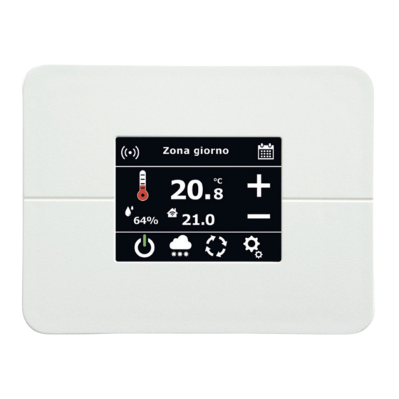
10. Main page The main page allows the display of the name of the zone at the top. At the centre there is the temperature detected and immediately below the setpoint temperature. The relative humidity is shown on the left as in the fi gure: The relative humidity is shown on the left as in the fi gure: In the table we fi nd the explanation of the single icons on the main page: WiFi connection status top left: •... -
Page 15: Stop
AUTOMATIC OPERATION. Identifi es that the programmable thermostat is setting the temperatures according to the programmable thermostat slots. TEMPORARY MANUAL OPERATION. Indicates a constant SETPOINT temperature up to the next slot change according to time schedule. Pressing this icon leads to operation in manual mode. MANUAL OPERATION. Indicates a constant SETPOINT temperature for all hours of the day. Pressing this icon restores automatic operation. -
Page 16: Programmable Thermostat Page
11. Programmable thermostat page From the main page by selecting ensures access to the setting page of the programmable thermostat slots. It is possible to activate up to a maximum of 8 different slots for the single days of the week. For each slot the SETPOINT temperature and the slot end time must be defi ned. -
Page 17: Settings Page
12. Settings page On the setting page, you can access the following pages by pressing on the icons: 12.1 Touch lock Select the icon to the side to lock the display for 20 seconds, allowing it to be cleaned with a damp cloth. 12.2 System date and clock settings Select the icon to the side to change the system date or time. -
Page 18: Display Settings
12.3 Display settings Select the icon to the side to access the display settings page. With the arrow keys you can scroll between the items Standby, Brightness, Home page and Timer SYNC. you can scroll between the items Standby, Brightness, Home page and Timer SYNC. you can scroll between the items Standby, Brightness, Home page and Timer SYNC. -
Page 19: Wifi Settings
12.4 WiFi settings Select the icon to the side to access the WiFi settings page as shown in the fi gure below. At the centre of the screen there is information regarding the confi gured network to which the device is connected or the network confi guration procedure information. The following icons are present in the image: Exit menu icon It allows you to activate or deactivate the WiFi connection It allows you to create a WiFi direct network for confi guring the connection with the APP It allows you to reset the WiFi network confi guration... - Page 20 12.5.1 Temperatures Through this page it is possible to modify the temperatures that can be set in the time schedules. Through this page it is possible to modify the temperatures that can be set in the time schedules. As in the fi gure, in the central part of the page there is the possibility to select a list of modifi able parameters such as temperatures.
- Page 21 In HEATING it is possible to select the following temperatures and functions: Comfort plus Comfort Night Economy Economy plus Stanby Antifrost GEO Away 12.5.2 Device info It allows you to view information on the WiFi programmable thermostat: serial number, name of the WiFi network to which it is connected, IP address and identifi cation number of the device.
- Page 22 12.5.4 Programs It is possible to activate up to a maximum of 6 programs: Summer (Cooling), Winter (Heating) and 4 confi gurable programs. The confi gurable programs can be set in cooling or heating mode. Through the programs page it is possible to change the name and type of the 4 confi gurable programs. As shown in the fi gure, in the centre of the page we have the list of programs that can be selected using the arrow keys As shown in the fi gure, in the centre of the page we have the list of programs that can be selected using the arrow keys To modify the selected program press the button To exit the menu press the button 12.5.4.1 Program modifi cation Use the button...
-
Page 23: User Configuration/2
12.5.6 Updates The updates page allows you to check and download the programmable thermostat updates, as well as disabling them. The updates page allows you to check and download the programmable thermostat updates, as well as disabling them. Updates are available only if the programmable thermostat is connected to the network. Updates are available only if the programmable thermostat is connected to the network. - Page 24 12.6.1 Temperature unit It allows to change the unit of measurement of the programmable thermostat temperature. It allows to change the unit of measurement of the programmable thermostat temperature. It allows to change the unit of measurement of the programmable thermostat temperature. Once selected in the menu, with the arrow keys Once selected in the menu, with the arrow keys it is possible to select degrees Celsius (°C) or Fahrenheit (°F).
-
Page 25: Installer Configuration
13. Installer confi guration The installer confi guration page allows you to change the bus confi guration, reset the WiFi card, reset the programmable thermostat to factory settings, set temperature and humidity offset, change the language, confi gure the type of output and set the maximum and minimum limits of the temperature setpoint. Further settings differ depending on the programmable thermostat model if in the RR confi guration (with 2 bistable relay outputs) or in the RA confi guration (with 1 relay and 1 analogue output). - Page 26 13.1.1.2 Installation type Change the type of automation installed by selecting the Installation Type and choose between: • lights • automations • lights + automations 13.1.1.3 System management There are 4 commands available for this submenu: ON, OFF, Edit e Remove. ON: activates the Klever function.
-
Page 27: Recovery Wifi
13.2 Recovery WiFi If you are having problems with the WiFi connection it is possible, through this function, to have access to a stable version for connecting the device. To perform this procedure contact Kblue assistance. 13.3 Temperature offset It allows to enter a negative or positive temperature offset with respect to the temperature actually detected by the sensor. It allows to enter a negative or positive temperature offset with respect to the temperature actually detected by the sensor. -
Page 28: Maximum Heating Setpoint Limit
13.5.3 Humidity comparison It allows to set the second output of the programmable thermostat for the relative humidity management. Once selected, the choice of humidity limit appears in the installer menu. 13.5.3.1 Humidity threshold It allows to set the humidity threshold beyond which the second programmable thermostat output is activated. 13.5.4 Boiler consent Available only in the RR version of the programmable thermostat, it allows you to replicate on the second relay output the behaviour of the fi rst output. -
Page 29: Programmable Thermostat Versions
14. Programmable thermostat versions The Smart Kult WiFi programmable thermostat is available in 2 versions. The fi rst includes 2 output relays (RR version), the second one a relay and an analogue output (RA version). 14.1 RR version In the version with 2 output relays there is the confi guration of the thermal differential (see the following paragraph). 14.1.1 Thermal differential Selecting Thermal Differential it is possible to modify the hysteresis parameter on temperature management. Selecting Thermal Differential it is possible to modify the hysteresis parameter on temperature management. - Page 30 14.2.4 Fan level 1 Determines the analogue percentage corresponding to the achievement of the Fan 1 threshold. Determines the analogue percentage corresponding to the achievement of the Fan 1 threshold. Once selected, use the arrow keys Once selected, use the arrow keys to enter the desired value and then press the key to exit by saving, otherwise press the key...
-
Page 31: Klever Lights And Automations Control
15. Klever lights and automations control Through the WiFi programmable thermostat or the Kblue MyTherm app it is possible to turn on/off all lights and open/ Through the WiFi programmable thermostat or the Kblue MyTherm app it is possible to turn on/off all lights and open/ close all automations through the scenario function. -
Page 32: Kblue Mytherm App
16. Kblue MyTherm app Through the Kblue MyTherm app it is possible to configure and manage one or more programmable thermostats linked to one or more systems. It is also possible to control the zones and the single automations configured with the Klever bus for automation management. Finally, through the user invitation section you can invite one or more people to your system, thus creating shared systems. 16.1 Login The use of the app requires the registration of a valid email. When you start the APP you need to enter your email and a password to proceed with the login. -
Page 33: Creating A Plant
16.1.2 Password recovery Through the login page you can recover your account password: you will be asked to enter the registered email address and an email will be sent to the indicated mailbox. 16.2 Creating a plant Each programmable thermostat that will be registered through the app requires a plant to be associated with. -
Page 34: Adding A New Programmable Thermostat
16.3 Adding a new programmable thermostat The addition of a programmable thermostat requires association with an installation. It is possible to add a programmable thermostat using the “ADD A THERMOSTAT” button or via the button at the top right that allows access to a drop-down menu where you can choose “ADD A THERMOSTAT”. Before starting the association procedure of a new programmable thermostat it is necessary to connect to the direct network generated by the programmable thermostat with the name “Kblue_XXXXXX” (to activate it, see the paragraph WiFi Configuration). - Page 35 Once connected to the direct network there are two ways to proceed, depending on the firmware version fo the thermostat: 1) xxx-112-112 or later firmware version: - select the WiFi network to connect from the list, then login to the selected network. 2) Previous firmware versions: - enter the name and password of the WiFi network to which you want to connect the thermostat.
-
Page 36: Dashboard
16.4 Dashboard The DASHBOARD is the main screen where the plants are listed and, within these, the programmable thermostats and the lights/automations present. In the example image in the “Home” plant there are 2 programmable thermostats called “Bathroom” and “Dining room”. There is also an AUTOMATIONS fi eld that allows you to manage lights and automations if the corresponding Klever bus are enabled. Through the button it is possible to select, through a drop-down menu, the PLANTS MANAGEMENT page, ADD A THERMOSTAT, ACCOUNT MANAGEMENT and the page that allows you to exit the account. - Page 37 If the control of the individual outputs has been enabled (chap. 6.1), by selecting the desired zone it is possible to access the controls of the individual elements. With reference to the image on the side, in the living area it is possible, for the example, to turn on the light called “Living Room”, while the roller shutter P0 is currently being opened.
- Page 38 16.4.2 Programmable thermostat From the DASHBOARD it is possible to view the main information of each programmable thermostat such as the current room temperature, the setpoint temperature and the set slot, which program is active and in what state the system is. slot, which program is active and in what state the system is.
- Page 39 16.4.2.1 Program selection The program selection screen allows you to activate one of the six available programs: Winter, Summer, Program 1, Program 2, Program 3, Program 4. Winter, Summer, Program 1, Program 2, Program 3, Program 4. Press and hold to access the confi guration screen of the active program.
- Page 40 16.4.2.2 Temperature setting The temperature setting screen allows you to modify the temperatures that can be set in time schedules. There are different pages for temperature setting of heating and cooling type programs. 16.4.2.3 Cronoprogramma The time schedule screen is accessible by rotating the phone from the screen of the thermostat.
- Page 41 Change time schedule The time schedule edit page can be accessed from the drop-down menu on the time schedule page. The changes only affect the active program. Selecting a slot from the graph and then one of the temperatures in the lower part, it is possible to modify the temperature associated with the time slot chosen.
- Page 42 16.4.2.4 Geolocation After activating the GEO Away function from the programmable thermostat (chap. 12.5.1) access the menu SYSTEM MANAGEMENT of the Kblue MyTherm app to enable the GEOLOCATION options. In this menu it is possible to configure the position of the system, the size of the area being travelled (with a radius that can be set from a minimum of 5 km to a maximum of 50 km) and the time of the hourly notification, i.e. that...
- Page 43 When all the users are within the area (whose size has been established in the SYSTEM MANAGEMENT menu), the programmable thermostat works according to the set option. When all the users are outside the area, the programmable thermostat sets the operation according to the Economy slot, thermostat sets the operation according to the Economy slot, displaying the icon.
- Page 44 16.4.3 Device setting The device setup screen allows you to change the name associated with the programmable thermostat and the unit of measurement. To make the changes successful, press the button “SAVE SETTINGS”; instead press the To make the changes successful, press the button “SAVE SETTINGS”; instead press the to cancel. 16.4.4 Edit network From the drop-down menu on the main page of the programmable thermostat, it is possible to access the page for changing the network of a programmable thermostat.
-
Page 45: Plants Management
16.5 Plants management From the DASHBOARD drop-down menu, selecting PLANTS MANAGEMENT, you can From the DASHBOARD drop-down menu, selecting PLANTS MANAGEMENT, you can access the page from which you can delete a plant by access the page from which you can delete a plant by , or access the plant edit page by selecting In the example to the side there are 2 plants of different types. The “Mountain house” plant... - Page 46 16.6.1 Change password To change the password of your account you need to enter the current password and replace it with the new one.Once entered it must be confirmed with the “SAVE PASSWORD” button. 16.6.2 Users invitation management Through “INVITE A USER” you access the screen where you need to enter a valid Kblue account in order to be able to share your plants with other people. After receiving an invitation, the user will see a new shared plant on his/her DASHBOARD.
- Page 48 - export@unical-ag.com - www.unical.eu Unical shall not be held liable for any inaccuracies due to transcription or printing errors. Furthermore, it reserves the right to modify its products as deemed necessary or useful, without aff ecting their essential features.
Need help?
Do you have a question about the KTsmart and is the answer not in the manual?
Questions and answers