Table of Contents
Advertisement
Quick Links
Advertisement
Table of Contents

Subscribe to Our Youtube Channel
Related Manuals for Electronics Line EL-4800

Summary of Contents for Electronics Line EL-4800
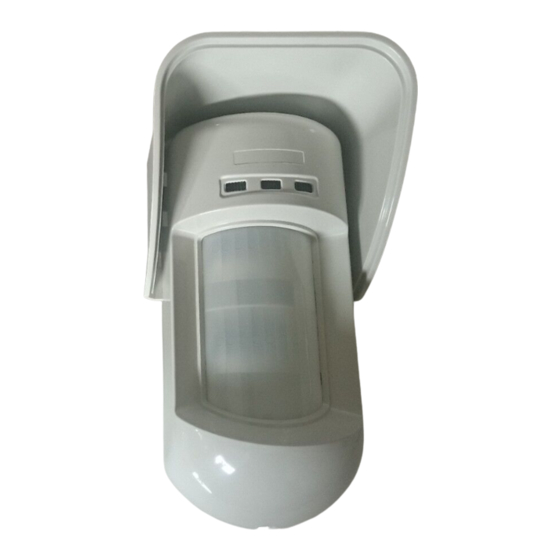
- Page 1 Two-Way Wireless Outdoor PIR Detector Model: EL-4800 Installation Instructions...
-
Page 3: Table Of Contents
Table of Contents Introduction ..........................4 Mounting ..........................4 Mounting Considerations...................... 4 Installing the Wireless Outdoor PIR Detector in challenging situations ......5 Wall Mount Installation ......................6 Flat Mounting: ........................6 45° angle Mounting (Left side mounting): ................6 Changing Back Tamper position: .................. -
Page 4: Introduction
Introduction Electronic Line’s Wireless PIR Outdoor Detector is a unique detector with signal processing based on two Passive Infrared (PIR) channels. The detector has an adjustable detection range. The detector is compatible with all Electronic Line’s Wireless and Hybrid systems. The following instructions describe the installation of the Wireless PIR Outdoor Detector. -
Page 5: Installing The Wireless Outdoor Pir Detector In Challenging Situations
Installing the Wireless Outdoor PIR Detector in challenging situations In the following situations, rapid and significant infrared radiation changes can happen in both PIR channels together, resulting in false alarms and therefore care should be taken. 1. Situations in which metal and/or glass objects measuring over 70cm (2’4”) in height from the ground are in the field of view of the detector (cars, metal gates, shutters, metal walls, windows, etc.) 2. -
Page 6: Wall Mount Installation
Wall Mount Installation Figure 1 Figure 2 Note: The installation knockouts numbering are marked on the back plate. 1. Open the Wireless PIR Outdoor Detector front cover (unlock C1, Figure 2. Release internal base (unlock I1, Figure 3. Select mounting installation as follows: Flat Mounting: Open knockouts on external base (Figure B1 - B4: Wall mounting knockouts... -
Page 7: Changing Back Tamper Position
Figure 5 Changing Back Tamper position: Left Side The back tamper is by default secured on the right Tamper side of the internal base (Rear view). If you wish to move it to the left side (rear view), do the following Right Side (Figure 5): Tamper... -
Page 8: Back Tamper Terminal Wiring
Back Tamper Terminal Wiring If you wish to use the back tamper (recommended) remove the short from the back tamper terminal block and connect the back tamper wires to the back tamper terminal block. BACK TAMPER Back Tamper in use Back Tamper not used Short Detection Range Adjustment... -
Page 9: Walk Test
Detection patterns (side view): Detection range with 1m (3'3") installation height: * Note: Length may vary according to environmental thermal conditions. Note: No effective detection occurs at distance less than 2.5 ft from the detector. Walk test Two minutes after applying power, walk test the protected area to verify proper operation. Adjust the moving PIR for required detection range and reliability. -
Page 10: Led Display
4. Verify that the detector has been identified by the receiver. Caution Notice Changes or modifications not expressly approved by Electronics Line may void the user’s authority to operate this equipment. Simultaneous transmissions from two different units may cause message interference resulting in loss of information. - Page 11 Detail A Detail B Standard Swivel Snaps Detail C Tamper (see Detail C) Figure 8 Connect the external base to the swivel using the dedicated snaps (Figure 9).
- Page 12 Figure 9 Note: Do not open or close the Swivel Assy Screw since it is used for connecting the swivel parts only (factory tightened). Secure external base to swivel with two screws fastened trough knockouts S1 and S2 (Figure 9). Insert the supplied angle locking screw from the external base through the angle locking screw knockout S3 on the external base to the standard swivel (Figure 9).
-
Page 13: Replacing Lenses
Replacing Lenses 1. Unlock the six screws that hold the lens holding sleeve from the back of the front cover. 2. To release the protective sleeve, gently push the lens from the external side of the front cover. 3. Disconnect the lens from the sleeve by gently pushing the lens clips that secure it to the sleeve. 4. -
Page 14: Technical Specification
Technical Specification Electrical Current consumption 20uA at 3 VDC (average) (standby) Current consumption 43mA at 3 VDC (Max. with LED OFF) (Alarm transmission) 53mA at 3 VDC (Max. with LED ON) Dead time (Normal Mode) 2.5 minutes Battery life 3 years (upon usage) Supervision transmission Every 10 minutes Range... - Page 15 RTTE Compliance Statement Hereby, Electronics Line declares that this equipment is in compliance with the essential requirements and other relevant provisions of Directive 1999/5/EC. For the CE Declaration of Conformity please refer to our website: www.electronics-line.com.
- Page 16 14 Hachoma St., 75655 Rishon Le Zion, Israel Tel: (+972-3) 963-7777 Fax: (+972-3) 961-6584 All rights reserved. No part of this document may be reproduced in any form without prior written permission from the publisher Electronics Line 3000 Ltd. 04/2013 5IN1859...
Need help?
Do you have a question about the EL-4800 and is the answer not in the manual?
Questions and answers