
Subscribe to Our Youtube Channel
Related Manuals for Gardner Denver Mako SCFS


Summary of Contents for Gardner Denver Mako SCFS
- Page 1 SCFS SCFS User Instruction User Instruction Manual Manual Document No. - 150SCFS Global-002...
- Page 2 Gardner Denver Mako Compressors 1301 N. Euclid Ave. Princeton, IL 61356 Phone: +1-(877) 272-1675 Fax: +1-(217) 224-7814 Website: www.makocompressors.com...
-
Page 3: Manual Configuration
GENERAL INFORMATION. These units are for filling Self Contained Breathing Apparatus (SCBA) or Self Contained Underwater Breathing Apparatus (SCUBA) with atmospheric air and are not suitable for use with any other gasses. They are designed and manufactured to give optimum performance with long life and reliability. -
Page 4: Maintenance
Maintenance To ensure the continued trouble-free operation of this unit it is important that periodic maintenance and servicing is carried out in accordance with the information given in the 'Maintenance' section of this manual. To assist in this matter your local MAKO Distributor can provide a number of optional maintenance agreements to suit your requirements. -
Page 6: Forward
Forward Notes On The Unit in addition, - relevant accident prevention regulations MAKO units are the result of many years of - generally recognized safety regulations research and development. This experience - national safety regulations combined with high quality standards have to be observed. -
Page 7: In Case Of Queries
Forward ModelNumber,Numerodumodele,Modellnummer, NumeroModello,N°modelo SerialNumber,Numerodeserie,Seriennummer, Numerodimatricola,N°serie DateofManufacture,Datedefabrication, Workorder,Bondetravail, Produktionsdatum, Arbeitsauftag, Datadifabbricazione, Pedido, Fechadefabricacion Ordinedilavoro HP,ch,PS,CV Diagramnumber,Nomrbredenimber,Diagramm-Zahl, Numerodelloschema,Numerodeldiagrama MotorRPM CompressorRPM,Compresseurr/min, www.makocompressors.com Moteurr/min KompressorU/min, MotorU/min Compressoregiri/min, Mako Compressors Motoregiri/min CompresorRPM 1301 N. Euclid Ave. Princeton, IL 61356 Pressure ChargingRate pi3/min Pression RegimedeCharge Druck Ladegeschwindigkeit Ph. -
Page 8: Guarantee
Forward Guarantee Operate this unit only if you have an exact knowledge of the machine taking into respect these facts. MAKO cannot be held responsible for the safe operation of the unit if it is used in a manner that does not correspond to the intended use, or for other applications which are not mentioned in this manual. -
Page 9: Table Of Contents
Table of Contents General Information Manual Configuration Maintenance Warranty Declaration Of Conformity Forward Notes On The Unit Certificate Of Conformity Intended Use Maintenance Servicing In Case Of Queries Notes General Guarantee Safety Regulations Technical Changes Table Of Contents Safety Regulations Identification Of Safety Guidelines General Safety Instructions Organizational Measures... - Page 10 Table of Contents Transportation And Installation Transport Machine Location Power Supply Operating Instructions Standard Fill Procedure 6.1.1 Filling From Compressor 6.1.1 Cascade Filling From Storage Automatic Flow Regulator Appendices Daily Log Book Sheet APP-A Engineering Drawings...
-
Page 11: Safety Regulations
Safety regulations Instructions, including supervisory Identification Of Safety responsibility and duty of notification for Guidelines taking into account in-plant factors, for example regarding work organization, MAKO is not liable for any damage or injury sequences of operations, personnel resulting from the non-observance of these assigned to certain tasks, are to be kept safety instructions or negligence of the with the operating manual. -
Page 12: Selection And Qualification Of Personnel; Basic Responsibilities
Safety regulations For the execution of maintenance work, Unauthorized changes to the machine are tools and workshop equipment adapted to not permitted for safety reasons. the task at hand are absolutely necessary. Genuine MAKO parts were especially designed and selected for this unit. The The personnel must be made familiar with installation and/or use of any parts other the location and operation of fire... -
Page 13: Normal Operation
Safety regulations The installed unit-specific safety valves only Check regularly that assume the pressure safeguarding function of this unit provided in currently valid - all means of protection are correctly fitted standards and regulations. and fixed. - all hoses and/or pipes within the system Electrical connections must meet the local are in good condition, firmly fixed and do regulations. -
Page 14: Special Work/Maintenance
Safety regulations Never operate the system at pressures Never use inflammable solvents or carbon which exceed the inlet pressure or fill tetrachloride to clean parts. Take pressure(s) as stated on the units precautions against poisonous vapors from nameplate. cleaning agents. All access panels have to be closed at all In any work concerning the operation, times during the operation of this unit. -
Page 15: Maintenance And Repair
Safety regulations To lower the risk of accidents, individual Never weld any pressure reservoir or parts and large assemblies being moved for change it in any way. replacement purposes should be carefully attached to lifting tackle and secured. Use If work which produces heat, flames or only suitable and technically correct lifting sparks has to be carried out on or near this gear and only utilize suspension systems... -
Page 16: Warning Of Special Dangers
Safety regulations Check the accuracy of pressure and After cleaning, remove all covers and temperature indicators at regular intervals. masking completely and allow the unit to If the admissible tolerance limits have been dry before returning unit to service! exceeded, these devices must to be replaced. -
Page 17: Gas, Dust, Steam And Smoke
Safety regulations Necessary work on live parts and elements Compressed-air lines must be laid and fitted must be carried out in the presence of a properly. Ensure that no connections are second person who can cut off the power exchanged. The fittings, lengths and quality supply in case of danger by operating the of hoses must comply with the technical main power switch. -
Page 18: Rooms Subject To Explosion Hazards
Safety regulations Rooms Subject To Explosion Hazards Danger ! Units with any type of electrical components must never be operated in areas subject to explosion hazards! (Exception: Special units with the corresponding technical modifications) -
Page 19: Symbols And Explanations
Safety regulations Symbols And Explanations The Following Symbols may be used on the unit. fig. 3.7-4 Read Operators Manual before continuing fig. 3.7-1 No Access for Unauthorized Personnel fig. 3.7-5 Read Technical Manual before continuing fig. 3.7-2 Warning, Electrical Shock or Electrocution fig. -
Page 20: Logs And Daily Inspection
Safety regulations fig. 3.7-7 fig. 3.7-10 Forklift, Left Most Lift Point Warning, Skin Puncture Danger Logs And Daily Inspections MAKO Supplies a daily log sheet, appendix- A, for used by the Operator. Make additional copies and create a daily log book. Keep this log with the unit at all times. -
Page 21: Daily Inspection And Log Entries
Safety regulations Daily Inspection & log Entries 1. - Check the log that no one has taken the unit out of service. 2. - After the unit is determined to be in service enter the date and time in the daily log and begin your inspections. -
Page 22: Layout And Function
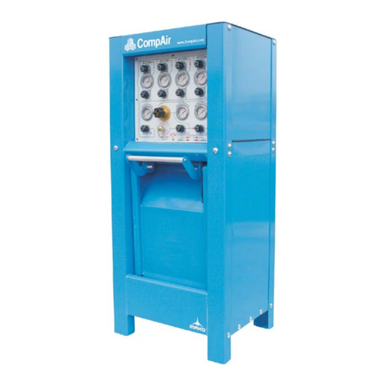
Layout and function fig. 4.1-1 Danger! Do not use system for any application other General Description than for breathing air system The Mako Stationary Containment Fill Station(SCFS) Units (See Fig. 4.1-1) No. of Weight incorporates all functions required to safely MODEL CYLINDERS lb. -
Page 23: Layout
Layout and function fig. 4.2-1 Overall View Layout 1. - Hinged Top Maintenance Panel. 2. - Air Management Panel - 4 Bank / Single Regulator Panel is shown. 3. - SCBA / SCUBA Fill Cells. 4. - Containment Shield Box Drawer. 5. -
Page 24: Panel Layout
Layout and function fig. 4.3-1 Overall View 6. - Regulator - This devise can be set to reduce the storage or compressor pressure to the proper fill pressure. Panel Layout 7. - Auxiliary Outlet - This connection will 1. - * To Bank - These valves control the allow this unit to be connected to a flow between the compressor and the secondary fill station or be used to fill other... -
Page 25: Transportation And Installation
Transportation and installation Transport Machine Location This unit requires the following Important! environment services and clearances: Care should be exercised when removing the unit from its shipping carton to avoid 1. - The unit should be located on a level any damage. -
Page 26: Operating Instructions
Operating Instructions 4. - Check that the regulator outlet pressure Standard Fill Procedure (see section 4.3 #8) matches the pressure rating of the bottle. Danger! Please read your owner's manual carefully Danger! for important safety information. All bottles being filled together must have the same pressure rating and filled at the Danger! lowest recommended fill rate. -
Page 27: 6.1.2 Cascade Filling From Storage
Operating Instructions 5. - Open fill station containment shield box 6.1.2 Cascade Filling From Storage drawer.(see section 4.2 #4) Cascade filling procedure will allow the user 6. - Load customer supplied bottles into the to fill more bottles from the system storage bottle cells(see section 4.2 #3) and connect banks before he must rely on the fill rate of fill hoses. - Page 28 Operating Instructions 21. - Close fill valve(see section 4.3 #11) 34. - Close “From Bank #4” valve.(see when bottle pressure(see section 4.3 #10) section 4.3 #3) and regulator outlet pressure(see section 4.3 #8) equalize at desired pressure and 35. - Start up compressor if it is not already continue to step #22.
-
Page 29: Automatic Flow Regulator
Operating Instructions Automatic Flow Regulator Danger! The entire filling cycle must be closely Description observed and the regulator outlet pressure The Automatic Flow Regulator (AFR) continuously adjusted when the regulator controls the flow of air to air cylinders at a outlet pressure is being set. - Page 30 Date Comments APP-A...
Need help?
Do you have a question about the Mako SCFS and is the answer not in the manual?
Questions and answers