Table of Contents
Advertisement
Advertisement
Table of Contents

Related Manuals for Power Storage Solutions SCIFP48100

Summary of Contents for Power Storage Solutions SCIFP48100
- Page 1 Application Manual...
- Page 2 Read this manual carefully before starting to install the battery. Keep these instructions for future reference. This document contains information that is the property of PWR Storage Solutions LLC., and provides for the sole purpose of the installation, operation, and maintenance of the products. No part of this publication is to be used for any other purpose, and it is not to be reproduced, copied, disclosed, transmitted stored in a retrieval system, or translated into any human or computer language, in any form, by any means in whole or in part, without prior written consent of the owner of the documents information.
- Page 3 Read and follow these instructions! The following precautions are intended to ensure your safety and prevent property damage. Before installing this product, be sure to read all safety instructions in this document for proper installation. Failure to comply with the instructions with this symbol may result in a serious accident, causing death or a severe injury.
-
Page 4: Table Of Contents
Table of Contents Table of Contents 1. Precautions ..........................8 1.1 General Safety Precautions ...................... 8 2. Installation Precautions ....................... 8 2. Product Introduction ........................9 2.1. Front Panel Function Introduction .................... 9 2.2 Product Specifications ........ - Page 5 Figures Figure 2-1: Front Panel Function Introduction Figure 4-1: Battery Module Installation Figure 5-1: Single Battery Connection Figure 5-2: Removing the Protecting Cover Figure 5-3: Communication Cable Connections between Battery and Computer Figure 5-4: Multiple Batteries Connections Figure 5-5: Communication Cable Connections among Multiple Batteries Figure 6-1: Communication Port Set Figure 6-2: Language Set Figure 6-3: System Monitoring Program...
- Page 6 About this Manual To make sure that you understand the proper procedures for safe operation, this section briefly describes the purpose, audience, organization, revision history, and acronyms and abbreviations. Purpose The purpose of this manual is to provide information for the safe and successful installation of the product.
- Page 7 Revision History Rev. Description Author Date 02/12/2021 First Release PWR Storage Solutions Acronyms and Abbrevia ons The following acronyms and abbreviations are used in this manual Abbreviations Full Name Battery Management System State Of Charge State Of Health...
-
Page 8: Precautions
Precautions 1. Precau ons 1.1 General Safety Precau ons The product provides a safe source of electrical energy when operated as intended and as designed. Potentially hazardous circumstances such as excessive heat or electrolyte mist may occur under improper operating conditions, damage, misuse and/or abuse. The following safety precautions and the warning messages described in this part must be observed. -
Page 9: Front Panel Function Introduction
Precautions Wear rubber gloves and safety shoes / boots. Ÿ Ÿ Do not put tools or any metal parts on the top of the batteries. Disconnect charging source and load before connecting or disconnecting terminals. Ÿ When moving batteries wear appropriate PPE clothing and equipment. Ÿ... -
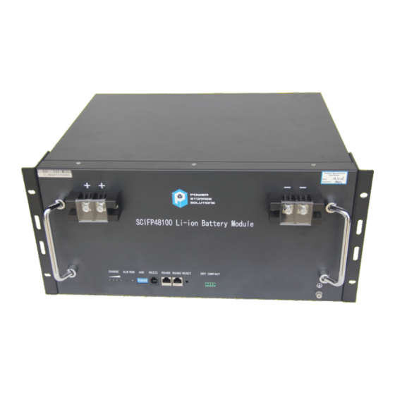
Page 10: Product Introduction
Product Introduction 3 4 5 Figure 2-2: Front Panel Function Introduction 1. Reset: When the BMS is in the dormant state, press the button for 1S to activate the BMS. Meanwhile, the LED indicator will be lit to show SOC of the battery. When the BMS is in the active state, press the button for 3S to cause battery go into sleep mode. -
Page 11: Product Specifications
Product Introduction 2.2 Product Specifica ons Table 2-1: Product Specifications Electrical Characteristics Typical Voltage Voltage Range 40.5 ~ 54.0V Max. Permanent Discharge Current Max. Permanent Charge Current Communication Interface RS485 / RS232 Operating Environment Charge Temperature 0 C to +55 C Discharge Temperature -20 C to +60 C Storage Temperature... -
Page 12: Protective Functions
Product Introduction Capacity LED System Mode Abnormal event Over charge All lit protection Temp Charging Flash 1 Flash 2 Indicate the SOC protection Overcurrent, All Out fail protection Normal Flash 3 Indicate the SOC Alarm Flash 3 Flash 2 Indicate the SOC Low voltage Flash 3 All Out... -
Page 13: Unpacking The Battery
Unpack the Battery Over temperature Max Temp≥ 60 ℃ Max Temp< 55℃ Protection (Charge) Min Temp>-15℃ Under temperature Min Temp≤ -20 ℃ Protection (Discharge) Min Temp>5℃ Under temperature Min Temp≤ 0 ℃ Protection (Charge) 300m Level 2 Current≥ 1.6C Overcurrent Protection (Charge) Level1 Current≥... -
Page 14: Table 3-2: Recommended Tools And Instruments
Unpacking the Battery Mounting Mount battery in Qty of 4 hardware in cabinet Connect the battery 2 per battery 2 Hole lug Optional adapter and rectifier using 1 - Negative 2 hole lugs 1 - Positive RS485 Apply to Modbus Optional communication protocol. -
Page 15: Visual Inspection Of The Modules
Battery Installation Insulated Torque Wrench Installing cables and busbars Insulated Sockets Installing cables and busbars Measure battery module’s Battery Tester voltage / Voltmeter 3.2 Visual Inspec on of the Modules After transporting the modules to the installation location, check for: Ÿ... -
Page 16: Battery Module Installation
Battery Installation Sharp Edges Wear gloves and other protective gear to prevent injury. Pinch Point Use caution when working in the enclosure to prevent injury. Heavy Object Can cause muscle strain or back injury. Use lifting aids and proper lifting techniques when moving trays, batteries and other heavy objects. -
Page 17: Figure 4-1: Battery Module Installation
Battery Installation Figure 4-1: Battery Module Installation (Example) § We recommend installing battery modules in the lower shelves first and proceeding to the top. Make sure racks are properly anchored. § The battery can be mounted in a standard 19 inch cabinet or rack. §... -
Page 18: Cable Connection
Cable Connection 5. Cable Connec on 5.1 Single Ba ery Connec on Before connecting the cables to the rectifier, confirm the output switch § of the rectifier has been turned of f to prevent the risk of arcing, fire, electric shock or burns. Before connection, make sure to close the battery. - Page 19 Cable Connection When tightening the screws, make sure they are at a straight angle from § the battery module terminals to avoid damage to the nuts inside. Assemble the screws using a Phillips-head within the fastening torque of § less than 8.0 Nm (79.88 kgf/cm). The power terminals, such as “+,”...
-
Page 20: Figure 5-3: Communication Cable Connections Between Battery And Computer
Cable Connection Figure 5-2: Single Battery Connection 3. Remove the negative fixing bolt with a Phillips Screwdriver and connect the negative output cable between the battery negative terminal of the battery and the rectifier. 4. Install the protective cover. 5. Arrange cables and fasten the battery cables to the perforated bracket. 6. -
Page 21: Connect Cables Of The Multiple Batteries In Parallel
Cable Connection 5.2 Connect Cables of the Mul ple Ba eries in Parallel When multiple batteries are wired in parallel, follow the cable connecting procedures below. 1. As shown in Figure 5-4, following the cable connection method of the single battery, connect the positive and negative cables between the Battery 1 and the Rectifier, Battery 2 and the Rectifier, and Battery N and the Rectifier respectively. -
Page 22: Figure 5-5: Communication Cable Connections Among Multiple Batteries
Cable Connection Module Battery Module Battery Picture Picture Address Module ID Address Module ID 0x01 0x09 0x02 0x0a 0x03 0x0b 0x04 0x0c 0x05 0x0d 0x06 0x0e 0x07 0x0f 0x08 Table 5-1: The Dialing Address Configuration of Each Battery 4. Connect the communication line between battery and computer Figure 5-5: Communication Cable Connections among Multiple Batteries... -
Page 23: Visual Inspection Of The Connection
Activate the Product 5.3 Visual Inspec on of the Connec on After connecting the battery, check for: Ÿ Usage of positive and negative cables. Connection of the positive and negative terminals. Ÿ All the bolts are tightened. Ÿ Cables attached and the appearance. Ÿ... - Page 24 Activate the Product 1.Installation of the USB to Serial driver. The first time the RS485 to Serial communications line is used, it is required the USB to Serial driver be installed. The driver is stored on memory medium. Shown in Figure 6-1after the connection of the communication line (USB converter to RS485) between the battery and the monitoring device, a new "Comm Port"...
-
Page 25: Figure 6-2: Language Set
Activate the Product Figure 6-2: Language Set 5. As shown in Figure 6-3, click “Ports” to select the Comm Port (can be seen in Device Manager) . When the display interface of “INFO” shows voltage, SOC and etc., indicating that the communication is successful, as shown in Figure 6-4. -
Page 26: Monitoring Software Function Introduction
Figure 6-3: System Monitoring Program 6.3 Monitoring So ware Func on Introduc on As shown in Figure 6-4, t he introduction to the interface of the monitoring software are as follows: Area 1: Main Menu: Software Operation Commands region. Ÿ Area 2: Submenu of “INFO”: In this area, you can choose which information to display. -
Page 27: Figure 6-4: Introduction Of Monitoring Interface
Activate the Product Figure 6-4: Introduction of Monitoring Interface (1) “SinglePack” button When you click the “SinglePack” button, it displays the content as shown in Figure 6-4. It can view the battery state according to the state indicator. As can be seen from area 5 and area 7, if the circle or rectangle turns green, it means that this function is running. -
Page 28: Figure 6-5: Multipacks Interface
Figure 6-5: MultiPacks interface (3) “Record” button When you click the “Record” button, it displays the content as shown in Figure 6-6. First, you need to check the “Display” option to display real-time records. You can choose the “Intervals” to display the time interval that you want. -
Page 29: Figure 6-6: Record
Figure 6-6: Record (4) “STORAGE” main button When you click the “STORAGE” button, it displays the content as shown in Figure 6-7. First, you need to click the “Read Record” button to display historical records. If you want to save the historical records, click the “Save Record”... -
Page 30: Inspection, Cleaning And Maintenance
Inspection, Cleaning and Maintenance Figure 6-7: Data Record Interface 7. Inspec on, Cleaning and Maintenance 7.1 General Informa on The battery is not shipped fully charged. It is recommended that the installation be completed Ÿ within 3 months after arrival; During the maintenance process, do not re -install the battery in the battery product. -
Page 31: Inspection
Inspection, Cleaning and Maintenance Never attempt to open or dismantle the battery. The inside of the battery does not contain Ÿ serviceable parts. Ÿ Disconnect the Li-Ion battery from all loads and charging devices before performing cleaning and maintenance activities Ÿ... - Page 32 7.5 Storage con nued at 40-70% when stored; When the battery is stored keep away from open flames or high temperatures, Ÿ and monitor state of charge if stored for long periods of time.
-
Page 33: Troubleshooting
The state of Health of your The loss is probably caused by battery battery is low aging and cannot be reversed Replace the batteries. If you require additional assistance please contact Power Storage Solutions at 888-813-5049 or via email at teams@pwrss1.com... -
Page 34: Transportation Requirements
There are a range of fines for companies (including OEMs) who do not comply with these regulations. All Power Storage Solutions batteries, covered in this document, have met the requirements of the UN Manual of Tests and Criteria, Fifth Revised Edition (ST/SG/AC.10/11/Rev.5 section 38.3 entitled "Lithium Metal and Lithium ion Batteries") and can therefore be transported. - Page 36 WWW.PWRSS1.com Contact us at teams@pwrss1.com 888-813-5049 972-980-4135...
Need help?
Do you have a question about the SCIFP48100 and is the answer not in the manual?
Questions and answers