
Related Manuals for S&T KBOX C-103-NGSF

Summary of Contents for S&T KBOX C-103-NGSF
- Page 1 USER GUIDE KBox C-103-NGSF User Guide, Rev. Proof of Concept KBOX C-103-NGSF - USER GUIDE www.kontron.com // 1...
- Page 2 KBox C-103-NGSF - User Guide, Rev. Proof of Concept This page has been intentionally left blank www.kontron.com // 2...
- Page 3 KBox C-103-NGSF - User Guide, Rev. Proof of Concept Disclaimer Kontron would like to point out that the information contained in this user guide may be subject to alteration, particularly as a result of the constant upgrading of Kontron products. This document does not entail any guarantee on the part of Kontron with respect to technical processes described in the user guide or any product characteristics set out in the user guide.
- Page 4 KBox C-103-NGSF - User Guide, Rev. Proof of Concept High Risk Applications Hazard Notice THIS DEVICE AND ASSOCIATED SOFTWARE ARE NOT DESIGNED, MANUFACTURED OR INTENDED FOR USE OR RESALE FOR THE OPERATION OF NUCLEAR FACILITIES, THE NAVIGATION, CONTROL OR COMMUNICATION SYSTEMS FOR AIRCRAFT OR OTHER TRANSPORTATION, AIR...
- Page 5 KBox C-103-NGSF - User Guide, Rev. Proof of Concept Revision History Revision Brief Description of Changes Date of Issue Author /Edito Initial Issue 2021-May Terms and Conditions Kontron warrants products in accordance with defined regional warranty periods. For more information about warranty compliance and conformity, and the warranty period in your region, visit http://www.kontron.com/terms-and-conditions.
-
Page 6: Symbols
KBox C-103-NGSF - User Guide, Rev. Proof of Concept Symbols The following symbols may be used in this user guide DANGER indicates a hazardous situation which, if not avoided, will result in death or serious injury. WARNING indicates a hazardous situation which, if not avoided, could result in death or serious injury. - Page 7 KBox C-103-NGSF - User Guide, Rev. Proof of Concept www.kontron.com // 7...
-
Page 8: For Your Safety
KBox C-103-NGSF – User Guide, Rev. Proof of Concept For Your Safety Your new Kontron product was developed and tested carefully to provide all features necessary to ensure its compliance with electrical safety requirements. It was also designed for a long fault-free life. However, the life expectancy of your product can be drastically reduced by improper treatment during unpacking and installation. -
Page 9: Lithium Battery Precautions
KBox C-103-NGSF - User Guide, Rev. Proof of Concept Lithium Battery Precautions If your product is equipped with a lithium battery, take the following precautions when replacing the battery. Danger of explosion if the battery is replaced incorrectly. Replace only with same or equivalent battery type recommended by the manufacturer. - Page 10 KBox C-103-NGSF - User Guide, Rev. Proof of Concept Environmental protection is a high priority with Kontron. Kontron follows the WEEE directive You are encouraged to return our products for proper disposal. www.kontron.com // 10...
-
Page 11: Table Of Contents
3.2.4. SATA Interfaces .............. 23 3.2.5. Internal USB 3.0 Interface ........... 24 3.2.6. Internal microSD Card and microSIM Card Interface ......24 3.3. KBox C-103-NGSF Variant ............26 3.3.1. X101/X201 – Power Input Connectors ........... 28 3.3.2. X102/X105/X108/X111 - Ethernet Connectors (ETH) ......29 3.3.3. - Page 12 - User Guide, Rev. Proof of Concept 4.2. (X206) WiFi ..............38 4.2.1. WiFi/BT ..............38 4.3. Optional Versions with Fan Tray - KBox C-103-NGSF ......39 5/ Accessing Internal Components ............ 40 5.1. Top Cover ..............41 5.2. Opening and Closing the KBox C-103-NGSF ........43 5.2.1.
- Page 13 11/ Technical Specifications ............74 11.1.1. Mechanical Specifications of the KBox C-103-NGSF ......75 11.1.2. Mechanical Specifications of the KBox C-103-NGSF with Fan Tray Option ..76 11.2. Environmental Specifications ..........79 11.3. Standards, Certifications and Directives Compliance ......79 11.4.
-
Page 14: List Of Tables
Table 6: WiFi/BT Expansion Card Option ..........38 Table 13: Power Consumption ............49 Table 14: Current and voltage provided in the KBOX C-103-NGSF per port ....49 Table 15: Maximum Power supplied on the PCIe Slot ........49 Table 19: Specifications of the internal M.2 Connectors ......54 Table 20: Navigation Hot Keys Available in the Legend Bar ...... - Page 15 Figure 36: Removing the cover (detail of the KBox C-103-NGSF) ....... 43 Figure 37: KBox C-103-NGSF - removing the right side cover ......44 Figure 38: KBox C-103-NGSF without top and right side cover (shown with a PCIe riser card) ................44 Figure 28: microSD/microSIM combo connector .........
-
Page 16: 1/ General Safety Instructions
KBox C-103-NGSF - User Guide, Rev. Proof of Concept 1/ General Safety Instructions Please read this chapter carefully and take careful note of the instructions, which have been compiled for your safety and to ensure to apply in accordance with intended regulations. If the following general safety instructions are not observed, it could lead to injuries to the operator and/or damage of the product;... - Page 17 KBox C-103-NGSF - User Guide, Rev. Proof of Concept www.kontron.com // 17...
- Page 18 KBox C-103-NGSF - User Guide, Rev. Proof of Concept Additional safety instructions for DC power supply circuits To guarantee safe operation of devices with DC power supply voltages larger than 60 volts DC or a power consumption larger than 240 VA, please observe that: ...
-
Page 19: Electrostatic Discharge (Esd)
8. Always place drives and boards PCB-assembly-side down on the foam. 1.2. Instructions for the optional Lithium Battery If ordered, your KBox C-103-NGSF is equipped with an optional lithium battery. For the replacement of this battery please observe the instructions described in section 0 “... -
Page 20: 2/ Shipment And Unpacking
If you notice any shipping damage or inconsistencies between the contents and your order, please contact Kontron for help and information. 2.2. Scope of Delivery KBox C-103-NGSF (Build as Proof of Concept) POWER-SUBCON PSC 1,5/ 3-F, 3-pin plug ... -
Page 21: Table 2: Product Identification Table
KBox C-103-NGSF - User Guide, Rev. Proof of Concept Figure 1 and Figure 17, pos. 9). Figure 1: Example of KBox C-103-NGSF type label KBox C-103-NGSF-24 2-A0DU-0004 (Space for certification) Table 1: Product Identification Table Syste Product Designation Product Identifikation... -
Page 22: 3/ System Overview
WiFi: via corresponding internal factory mounted adapter module (X206) The KBox C-103-NGSF is a fanless system with a compact metal chassis with cooling fins which can be optionally equipped with a fan tray for active cooling The rated voltage range of the mains can be found on the type label. The type label is located at the right side of the device (Figure 17, pos. -
Page 23: Optional Rtc Lithium Battery (Internally-Accessible)
Interface ® The KBox C-103-NGSF is equipped with a Mini PCIe interface on the KBox C-103-NGSF baseboard. The Mini PCIe interface connector is located on the lower side of the baseboard and is not accessible in the field. This interface connector is intended to be used for Fieldbus or WiFi expansion. -
Page 24: Internal Usb 3.0 Interface
- User Guide, Rev. Proof of Concept 3.2.5. Internal USB 3.0 Interface The baseboard of KBox C-103-NGSF provides one USB3.0 interface (USB A header) and space for a USB A module. This connector can be used to install an internal USB device e.g. a USB Dongle. -
Page 25: Figure 4: Bottom Side View
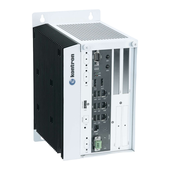
KBox C-103-NGSF - User Guide, Rev. Proof of Concept Figure 2 to Figure 8: Views of a KBox C-103-NGSF Figure 2: Bottom side view Figure 4: Front Figure 5: Front side view config. side view config. Figure 3: Right side... -
Page 26: Kbox C-103-Ngsf Variant
KBox C-103-NGSF - User Guide, Rev. Proof of Concept 3.3. KBox C-103-NGSF Variant Figure 9: KBox C-103-NGSF - front view (shown with removable drive bays and without mounting brackets) www.kontron.com // 26... -
Page 27: Figure 12: Block Diagram - Kbox C-103-Ngsf
X 206 WLAN antenna (optional Drive 1/2 (SATA X 101 HDD/SSD (24V DC) drive bays) 1. Side of KBox C-103-NGSF with cooling fins 2. Top side cover with knurled screws Figure 10: Block Diagram - KBox C-103-NGSF-x www.kontron.com // 27... -
Page 28: X101/X201 - Power Input Connectors
KBox C-103-NGSF - User Guide, Rev. Proof of Concept 3.3.1. X101/X201 – Power Input Connectors www.kontron.com // 28... -
Page 29: X102/X105/X108/X111 - Ethernet Connectors (Eth)
The 3-pin connector (X101) and the optional second power connector (X201) provide the power connection of the KBox C-103-NGSF system to an appropriate DC main power supply (see Figure 11 and Figure 9). For pin assignment refer to the subsection 12.1.1. -
Page 30: X112/X113/X203 - Displayports
3 Rescue button (RSQ) 4 Rescue LED (RSQ) The power button (PWR, Figure 12, pos. 1, Figure 9) is used to power the KBox C-103-NGSF on or off. By pressing the power button for longer than four seconds a forced system shutdown will be initiated, before the power to the system is turned off. -
Page 31: Rescue Button And Rsq Led
KBox C-103-NGSF - User Guide, Rev. Proof of Concept To perform an orderly shutdown of the system, press the PWR button and the system shuts down under the control of the operating system. Once the system has been shut down, it can restarted by pressing the PWR button (assuming that power is still applied to the main input power connector, X101). -
Page 32: Pci/Pcie Expansion Slots
- User Guide, Rev. Proof of Concept 3.3.10. PCI/PCIe Expansion Slots The KBox C-103-NGSF provides on the front side two slots (see also Figure 9 for KBox C- 103-NGSF) for system expansion with PCIe expansion card via riser card. PCIe Slot 1 is not functional! Use only Slot two for PCIe expansion cards! www.kontron.com... -
Page 33: Internal Or Removable 2.5" Sata Hdds/Ssds
3.3.11. Internal or Removable 2.5" SATA HDDs/SSDs Depending on the ordered system configuration, your KBox C-103-NGSF can be equipped with up to two drive bays for 2.5" removable SATA HDDs/SSDs (refer to Figure 9, Figure 10) or one internal mounting frame for 2x 2.5"... -
Page 34: Installing/Removing The Removable Hdd/Ssd
KBox C-103-NGSF - User Guide, Rev. Proof of Concept 3.3.11.1. Installing/Removing the removable HDD/SSD To install/remove a removable drive, please perform the following steps: 1. Pull out the lever (Figure 15, pos. 3) of the drive cover (Figure 14, pos. 2) and release it. -
Page 35: Left And Right Side View
KBox C-103-NGSF - User Guide, Rev. Proof of Concept 3.4. Left and Right Side View Figure 17: Right side of the KBox C-103- Figure 18: Left side of the KBox C-103- NGSF system NGSF system Top side access cover with knurled screws Screws that secure the COMExpress ®... -
Page 36: Rear Side View
Do not place any objects onto the device. 3.6. Rear Side View The KBox C-103-NGSF is designed for wall mounting, in vertical position inside of a control cabinet. Please do not remove the red marked screws (see Figure 21, pos. 2 and pos. - Page 37 KBox C-103-NGSF - User Guide, Rev. Proof of Concept The KBox C-103-NGSF with the stud marked with a “Functional Earth” symbol (Figure 21) has to be grounded to an appropriate “common earth” connection point. www.kontron.com // 37...
-
Page 38: 4/ System Extensions
Fan Tray: an additional component connected to the KBox C-103-NGSF-4, KBox C-103- NGSF and KBox C-103-NGSF-1 You have to order these components separately, in order to extend your KBox C-103-NGSF at the factory. Example of system configuration, see below: 4.1. -
Page 39: Optional Versions With Fan Tray - Kbox C-103-Ngsf
- User Guide, Rev. Proof of Concept 4.3. Optional Versions with Fan Tray - KBox C-103-NGSF By using a fan tray, the KBox C-103-NGSF can be operated in a control cabinet with extended ambient temperature; refer to the specified values in the section 11.2 “Environmental Specifications”... -
Page 40: 5/ Accessing Internal Components
Before removing the cover of the device, make sure that the device is powered off and disconnected from the power supply. Before you upgrade the KBox C-103-NGSF with expansion cards, pay attention to the power specifications in chapter 11/ “Technical Specifications”... -
Page 41: Top Cover
The cover description can be applied to all system variants, under consideration of the different mechanical specifications of the KBox C-103-NGSF When used as intended the KBox C-103-NGSF is to be operated only in closed condition. Only when the right side cover is fixed with the screws (Figure 17, pos. - Page 42 KBox C-103-NGSF - User Guide, Rev. Proof of Concept 1 Inside of the top 3 Centering bracket (on the rear side) cover 4 Air exhaust openings 2 Rear part of the top 5 Fixing bracket with knurled screws on cover the front side www.kontron.com...
-
Page 43: Opening And Closing The Kbox C-103-Ngsf
Disconnect all peripherals. 2. The KBox C-103-NGSF should lay on a flat, clean surface with the top side facing upwards. 3. Loosen the knurled screws, which secure the top cover on the front of the system (see Figure 9 and Figure 24). -
Page 44: Figure 37: Kbox C-103-Ngsf - Removing The Right Side Cover
(Figure 26 and Figure 17, pos. 3). Pull the right side cover out, to detach it from the sideways mounted bolts. Put the right side cover and the screws aside for later use. Figure 27: KBox C-103-NGSF without top and right side cover (shown with a PCIe riser card) www.kontron.com... - Page 45 KBox C-103-NGSF - User Guide, Rev. Proof of Concept 1 Screws to fix the PCIe slot 5 3x M.2 sockets (2x Type B, 1x Type M; bracket or the I/O bracket of the from left to right: J13, J17, J18) (J17: non...
-
Page 46: Dip Switch
Which is non-functional 5.2.2. Expansion Socket for PCIe Mini Cards Depending on the system configuration ordered, your KBox C-103-NGSF can be extended with a PCIe Mini card. The KBox C-103-NGSF provides one internal Mini PCIe socket for PCIe Mini cards. The Mini PCIe socket is on the lower side of the baseboard and can be only at factory equipped with an expansion card. -
Page 47: Installing/Removing An M.2 Module
45° and push it down until it lies on the the fixing clip. 6. Secure the M.2 on the fixing bolt with the corresponding fixing screw. 7. In order to close the KBox C-103-NGSF, proceed in reverse order (step 6 to 1 of the section 5.2 “Opening and Closing the KBox C-103-NGSF”. -
Page 48: Installing/Removing A Microsd/Microsim Card
(see 5. Figure 28). 6. In order to close the KBox C-103-NGSF, proceed in reverse order (step 6 to 1 of the section 5.2 “Opening and Closing the KBox C-103-NGSF”). To remove a microSD or a microSIM card, please proceed according to the steps described: 1. -
Page 49: 6/ Power And Thermal Considerations
2 A total 3 A total 6.2. Convection Cooling The KBox C-103-NGSF is designed for convection cooling within the specified ambient air temperature ranges. Therefore it is imperative that air flow to and from the unit is guaranteed. In addition, implementers must empirically verify the cooling concept for the KBox C- 103-NGSF including optionally installed devices prior implementing the unit in the intended application. - Page 50 KBox C-103-NGSF - User Guide, Rev. Proof of Concept at higher ambient temperature conditions and provides a higher air flow through the chassis providing a better cooling of the system internal components. www.kontron.com // 50...
-
Page 51: Minimum System Clearance
6.5. Third Party Components When the KBox C-103-NGSF is extended and configured with third party components like PCIe extension cards and drives (HDD or SSD), it has to be taken into account that the air temperature inside the system is higher than the ambient temperature. An approximately internal temperature rise is given. -
Page 52: 7/ Installation Instructions
Kontron rejects all liability for any and all damages resulting from operation of the unit with foreign objects inside the chassis. The KBox C-103-NGSF has to be installed and operated only by trained and qualified personnel. The KBox C-103-NGSF system is designed for usage within control cabinets only. - Page 53 KBox C-103-NGSF - User Guide, Rev. Proof of Concept Use copper conductors only if the field wiring terminal is only for connection to copper wire. Minimum temperature rating of the cables connected to the field wiring terminals is 77°...
-
Page 54: Specifications Of The Internal M.2 Connectors
Your KBox C-103-NGSF is supplied with assembled mounting brackets. The key holes of the upper and lower mounting brackets (Figure 21, pos. 1 and pos. 3) allow you to mount the KBox C-103-NGSF to a mounting side of the control cabinet in vertical position. This is the only permitted operating position. -
Page 55: Figure 48: Keep Out Area For Mounting Around Kbox C-103-Ngsf (Front Side View Without Fan Tray)
- User Guide, Rev. Proof of Concept Figure 29: Keep out area for mounting Figure 30: Keep out area for mounting around around KBox C-103-NGSF (front side view without KBox C-103-NGSF (front side view with fan tray) optional fan tray) www.kontron.com... -
Page 56: Dc Power Plug Terminal
- User Guide, Rev. Proof of Concept 7.3. DC Power Plug Terminal The KBox C-103-NGSF is connected by a Phoenix connector to a DC power source via a DC power supply wiring (only the Phoenix power plug terminal is included). -
Page 57: Side Wall Mounting (Option)
The key holes of the upper and lower mounting brackets (Figure 32, pos. 3 and pos. 6) allow you to mount the KBox C-103-NGSF to a mounting side of the control cabinet in vertical position. This is the only permitted operating position. The lower side wall mounting bracket has different holes for mounting with and without fan tray (Figure 32, pos. -
Page 58: 8/ Starting Up
The DC input connector (Figure 9 and Figure 11 marked X101) is located on the front side of the KBox C-103-NGSF. The KBox C-103-NGSF will be connected to a DC main power supply via the supplied Phoenix power plug terminal (see Figure 31) and corresponding power wires (prepared as described in the subsection 7.3.1 “Cabling”). -
Page 59: Power Off/On Procedure
8.2. Power OFF/ON Procedure As the KBox C-103-NGSF is equipped with an internal hold-up buffer, it can’t be powered off/on immediately. The buffer time depends on the power consumption and load on the KBox C-103-NGSF processor and peripherals. -
Page 60: 9/ Maintenance And Cleaning
KBox C-103-NGSF. 9.1. Replacing the Lithium Battery If your KBox C-103-NGSF is equipped with the optional lithium battery (CR 2032, 3V, internally accessible), and you have to replace it, please proceed as follows: 1. -
Page 61: Preventive Maintenance For Ssd Drives
To replace fan tray, proceed as follows: 1. Ensure to have access to the bottom side of the KBox C-103-NGSF. The fan tray (Figure 35, pos. 1 and Figure 36, pos. 2) may be replaced without removing the air filter holder (Figure 35, pos. 4). - Page 62 KBox C-103-NGSF - User Guide, Rev. Proof of Concept 7. Secure the fan tray by fastening the knurled screws (Figure 35, pos. 2). By fastening of the knurled screws the proper insertion of the fan tray into the internal socket (Figure 36, pos. 10) is ensured.
-
Page 63: Cleaning The Air Filter
5 Fan tray slot To replace the air filter, proceed as follows: 1. Ensure to have access to the bottom side of the KBox C-103-NGSF. The air filter may be replaced without removing the fan tray (Figure 35, pos. 1). -
Page 64: Figure 58: Kbox C-103-Ngsf With Removed Fan Tray And Removed Air Filter
- User Guide, Rev. Proof of Concept Defective components may only be replaced by Kontron original spare parts. Air filter: part number: 9-5000-1098 (for KBox C-103-NGSF) Figure 36: KBox C-103-NGSF with removed fan tray Figure 37: Filter mat Holder without and removed air filter... - Page 65 KBox C-103-NGSF - User Guide, Rev. Proof of Concept 1 KBox C-103-NGSF assembled with the 6 Removed air filter optional fan tray slot 7 Air filter holder with knurled screw 2 Removed fan tray 8 Positioning latches of the air filter...
-
Page 66: 10/ Uefi Bios
5. 5. A Setup menu appears. The KBox C-103-NGSF-x uEFI BIOS Setup program uses a hot key navigation system. The hot key legend bar is located at the bottom of the Setup screens. The following table provides a list of navigation hot keys available in the legend bar. - Page 67 KBox C-103-NGSF - User Guide, Rev. Proof of Concept <RETURN> <RETURN> key executes a command or selects a submenu www.kontron.com // 67...
-
Page 68: Setup Menus
KBox C-103-NGSF - User Guide, Rev. Proof of Concept 10.2. Setup Menus The Setup utility features menus listed in the selection bar at the top of the screen: Main Advanced Chipset Security Boot Save & Exit The left and right arrow keys select the Setup menus. -
Page 69: Advanced Setup Menu
KBox C-103-NGSF - User Guide, Rev. Proof of Concept 10.2.2. Advanced Setup Menu The Advanced Setup menu provides sub-screens and second level sub-screens with functions, for advanced configuration and Kontron specific configurations. Setting items, on this screen, to incorrect values may cause system malfunctions. -
Page 70: Boot Setup Menu
KBox C-103-NGSF - User Guide, Rev. Proof of Concept HDD security passwords cannot be cleared using the above method. 10.2.5. Boot Setup Menu The Boot Setup menu lists dynamically generated boot device priority order. 10.2.6. Save and Exit Setup Menu The Save and Exit Setup menu provides functions for handling changes made to the uEFI BIOS settings and exiting of the Setup program. -
Page 71: Entering The Uefi Shell
KBox C-103-NGSF - User Guide, Rev. Proof of Concept The uEFI Shell forms an entry into the uEFI boot order and is the first boot option by default. 10.3.1.1. Entering the uEFI Shell To enter the uEFI Shell, follow the steps below: 1. -
Page 72: Uefi Shell Scripting
KBox C-103-NGSF - User Guide, Rev. Proof of Concept 10.4. uEFI Shell Scripting 10.4.1. Startup Scripting If the ESC key is not pressed and the timeout has run out then the uEFI Shell tries to execute some startup scripts automatically. It searches for scripts and executes them in the following order: 1. -
Page 73: Updating The Uefi Bios
For the BIOS update the customer should follow the instructions in the Readme.txt BIOS package. 10.5.2. uEFI BIOS Recovery In case of the standard SPI boot flash being corrupted the KBOX C-103-NGSF must be returned to Kontron to repair the system. There is no recovery flash available. www.kontron.com // 73... -
Page 74: 11/ Technical Specifications
KBox C-103-NGSF - User Guide, Rev. Proof of Concept 11/ Technical Specifications Table 12: Technical Specifications KBox C-103-NGSF Family Installed COM Baseboard with COMe-cTL6 (see Device passport) Express Module and Baseboard BIOS AMI Aptio V uEFI Controls Power button (PWR) -
Page 75: Mechanical Specifications Of The Kbox C-103-Ngsf
KBox C-103-NGSF - User Guide, Rev. Proof of Concept 11.1.1. Mechanical Specifications of the KBox C-103-NGSF Figure 40: Dimensions: right side (KBox C- Figure 41: Dimensions: front side with key 103-NGSF) holes (KBox C-103-NGSF) Figure 42: Dimensions: detail key hole (KBox... -
Page 76: Mechanical Specifications Of The Kbox C-103-Ngsf With Fan Tray Option
KBox C-103-NGSF - User Guide, Rev. Proof of Concept 11.1.2. Mechanical Specifications of the KBox C-103-NGSF with Fan Tray Option Figure 44: Dimensions: right side Figure 45: Dimensions: front side with key (KBox C-103-NGSF with fan tray option) holes (KBox C-103-NGSF with fan tray option) - Page 77 KBox C-103-NGSF - User Guide, Rev. Proof of Concept www.kontron.com // 77...
-
Page 78: Table 49: Mechanical Specifications Of The Kbox C-103-Ngsf
KBox C-103-NGSF - User Guide, Rev. Proof of Concept Table 13: Mechanical Specifications of the KBox C-103-NGSF Dimensions KBox C-103-NGSF (Standard KBox C-103-NGSF (with optional Version) Fan Tray) Height with mounting brackets: 290 mm with mounting brackets: 324 mm (11.42") (12.756") -
Page 79: Environmental Specifications
10 Hz - 150 Hz, 1 G, acc. to IEC 60068-2-6 Pollution Degree 11.3. Standards, Certifications and Directives Compliance Because the KBOX C-103-NGSF is a Proof of Concept System, there are no certifications that can be assured. www.kontron.com // 79... -
Page 80: Power Supply Specification
AC power loss and start up under peak loading. Connect the product only to a power supply desiged to achive NEC Class-2 and Limited Power Source (LPS). Table 15: KBox C-103-NGSF-x Electrical Specification Nominal Input Voltage 24 VDC... - Page 81 KBox C-103-NGSF - User Guide, Rev. Proof of Concept and additional electrical factors. To determine the required “off state”, each case must be considered individually. For more information, contact Kontron Support. www.kontron.com // 81...
-
Page 82: Power Consumption
KBox C-103-NGSF - User Guide, Rev. Proof of Concept 11.4.2. Power Consumption The used external power supply must be capable of delivering the product with the required power when configured with all components. The total power consumption depends on factors such as the CPU, interfaces, and system/memory expansion. -
Page 83: 12/ Standard Interfaces - Pin Assignments
KBox C-103-NGSF - User Guide, Rev. Proof of Concept 12/ Standard Interfaces – Pin Assignments Low-active signals are indicated by a minus sign. 12.1.1. (X101) Power Input Connector Table 16: (X101) Power Input Connector Signal Name 3-pin POWER SUBCON (male) -
Page 84: X103, X106, X109) Usb 3.0 Ports
KBox C-103-NGSF - User Guide, Rev. Proof of Concept 12.1.3. (X103, X106, X109) USB 3.0 Ports Table 18: (X103, X106, X109) USB 3.0 Ports Signal Name Signal Name 9-pin USB Connector Type A Version 3.0/2.0 USB 2.0 contact pins USB 3.0 contact pins... -
Page 85: X114) Serial Interface Com 1 (Rs232, Rs422, Rs485)
KBox C-103-NGSF - User Guide, Rev. Proof of Concept 12.1.6. (X114) Serial Interface COM 1 (RS232, RS422, RS485) The mode cannot be selected in the BIOS Table 21: (X114) Serial Interface COM 1, configured as RS232) Signal Name 9-pin D-SUB Connector (male) -
Page 86: Table66: (X114) Serial Interface Com 1 And Com2, Configured As Dual Rs422
KBox C-103-NGSF - User Guide, Rev. Proof of Concept Signal Name 9-pin D-SUB Connector (male) TxD/RxD- (COM1 Data -) TxD/RxD+ (COM1 Data+) (Signal Ground) TxD/RxD- (COM2 Data -) TxD/RxD+ (COM2 Data+) Table25: (X114) Serial Interface COM 1 and COM2, configured as dual RS422... -
Page 87: Optional Interfaces Via Adapter Modules
KBox C-103-NGSF - User Guide, Rev. Proof of Concept 12.2. Optional Interfaces via Adapter Modules 12.2.1. (X201) 2 Power Input Connector For pin assignment, refer to 12.1.1. 12.2.2. (X 203) 3 DisplayPort For pin assignment, refer to 12.1.5. This port must be factory installed and configured only. -
Page 88: 205) Serial Port Rs232/Rs422
KBox C-103-NGSF - User Guide, Rev. Proof of Concept 12.2.3. (X 205) Serial Port RS232/RS422 This port must be factory installed and configured only. When you order the KBox C-103 with this extended interface via RS232/422 adapter module, you have to specify in your ordering: ... -
Page 89: Appendix A: List Of Acronyms
KBox C-103-NGSF - User Guide, Rev. Proof of Concept Appendix A: List of Acronyms Table 28: List of Acronyms (Example) Application Programming UEFI Unified Extensible Firmware Interface Interface Base Management Controller Very Low Profile Command-Line Interface Computer-on-Module Error Checking and Correction... -
Page 90: About Kontron - Member Of The S&T Group
KBox C-103-NGSF – User Guide, Rev. Proof of Concept About Kontron – Member of the S&T Group Kontron is a global leader in IoT/Embedded Computing Technology (ECT). As a part of technology group S&T, Kontron, together with its sister company S&T Technologies, offers a combined portfolio of secure hardware, middleware and services for Internet of Things (IoT) and Industry 4.0 applications.
Need help?
Do you have a question about the KBOX C-103-NGSF and is the answer not in the manual?
Questions and answers