Table of Contents
Advertisement
Quick Links
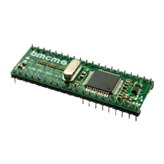
USB-PIO-OEM
Digital I/O Interface (USB)
24 Channels. Digital.
Signal Output & Monitoring.
Record and output digital signals. The
USB-PIO-OEM features three 8-bit bidirectional
ports. The port lines are led through to the
module pins.
OEM. Simply Integrate.
The module is an OEM version of the USB-PIO
of bmcm to equip your device with a modern and
powerful USB interface. Special emphasis was
put on the easy implementation of both hardware
and software components.
Extra Small. Extra Low-Priced.
In size and construction type, the USB-PIO-OEM
module looks like a 40-pin DIL IC and can easily
be integrated in other devices. Not only the size is
extra small but also the price.
Function diagram
Plug & Play.
The connection to the PC is realized via USB.
The USB-PIO-OEM provides all typical USB
features (e.g. Plug&Play, Hot-Plug). Up to 127
devices can be connected and installed during
operation.
Powered by USB.
The device is supplied with power via the USB
interface. This reduces cabling efforts to a
minimum and makes mobile measurements a lot
easier.
Open for Everyone.
Widely supported: The USB-PIO-OEM can be
®
used under Windows
XP/7/8/10 as well as under
MAC OS X, Free BSD, and Linux. The OEM
module is 100% software compatible to the USB-
PIO. The complete software for installation and
programming of the device is included for free.
NextView
4. Try for Free.
®
The module is supported by NextView
software for data acquisition and analysis. A fully
functional 30-day trial is included with delivery
to directly test the functionality of the
USB-PIO-OEM.
Accessory. Just Makes it Easier.
For testing purposes or to make your own
developments easier, the test tool
USB-PIO-OEM-TL is available. It provides
standard connectors for the digital lines and the
USB bus. In addition, 24 LEDs allow immediate
status control of the individual I/O pins.
4, the
®
Advertisement
Table of Contents

Related Manuals for bmcm USB-PIO-OEM 38


Summary of Contents for bmcm USB-PIO-OEM 38
- Page 1 OEM. Simply Integrate. Powered by USB. The module is an OEM version of the USB-PIO of bmcm to equip your device with a modern and The device is supplied with power via the USB powerful USB interface. Special emphasis was interface.
- Page 2 USB-PIO-OEM Board View and Pin Assignment The USB-PIO-OEM features a µ-controller providing 24 digital channels with TTL/CMOS level (low: 0V..1V; high: 3.0V..5V) designed as three 8-bit digital ports A, B, C. The lines are bidirectional. The direction is set to input or output in groups of 8 (port C: 4) via software. The connections to the digital interfaces are accessible at the pins of the USB-PIO-OEM.
-
Page 3: Interfacing Examples
USB-PIO-OEM 2 Interfacing Examples Connect Input Signal Exemplarily, the connection of an input signal at pin 3 and 10 of the USB-PIO-OEM is illustrated. The 1k resistor and the 100pF capacitor have protective and noise suppressive functions. For voltages higher than 5V a voltage divider is required (see calculation below chapter 2.3). -
Page 4: Software Installation
Under MAC OS X, FreeBSD and Linux, driver installation is not necessary. 3.1.1 Install Driver Package The prior installation of the bmcm driver package BMCM-DR to the hard disc of your PC makes the driver ®... -
Page 5: Plug&Play Installation
Check Installation ® The entry "Data Acquisition (BMC Messsysteme GmbH)" is included in the Windows Device Manager after successful installation displaying the installed bmcm hardware. To open the Device Manager, proceed as follows: ® - Windows 7: Start / Control Panel / System and Security / System / Device Manager ®... -
Page 6: Digital Inputs And Outputs
USB-PIO-OEM 4 Test Tool USB-PIO-OEM-TL Figure 1 The test adapter USB-PIO-OEM-TL is provided to directly test the functions of the USB-PIO-OEM. Plug the OEM module onto the 40-pin socket. Make sure the orientation of the module is correct (see Figure 1, pin 1 top right) to avoid damages of the module. -
Page 7: Usb Connection
USB-PIO-OEM Do not apply voltage to the ports without the relevant protective circuit. Two outputs connected with each other may get damaged by the high flow of current. The digital inputs are equipped with an internal 100k pull-down resistor for open inputs to be constantly low. -
Page 8: Technical Data
Do not dispose of the product in the domestic waste or at any waste collection places. It has to be either duly disposed according to the WEEE directive or can be returned to bmcm at your own expense. 6 Technical Data (typical at 20°C, after 5min., +5V supply)
Need help?
Do you have a question about the USB-PIO-OEM 38 and is the answer not in the manual?
Questions and answers