Advertisement
Advertisement

Related Manuals for JTX Fitness Cyclo-6

Summary of Contents for JTX Fitness Cyclo-6
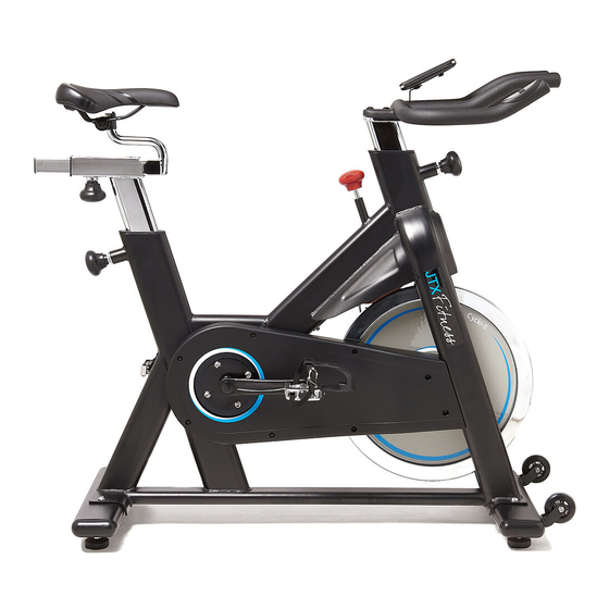
- Page 1 JTX Cyclo-6...
-
Page 2: Table Of Contents
CONTENTS SAFETY GUIDELINES…………………………………………………………3 MAINTENANCE GUIDELINES……………………. ………………………4 EXPLODED DRAWING ………………….……………………………………5 PARTS LIST…………………………………. ……………………………………6 INSTALLATION…………………………………………………………………8 OPERATION……………………………………………………………………...17 TRAINING GUIDELINES……………………………………………………….18 - 2 -... -
Page 3: Safety Guidelines
5. Do not remove feet from the pedals while the cranks are in motion. 6. Dry the bike after each use to remove sweat and moisture. Wipe your Cyclo-6 with a mild, non-abrasive cleaner and water solution. To avoid damaging the finish on the bike, never use a petroleum-based solvent when cleaning. -
Page 4: Maintenance Guidelines
MAINTENANCE GUIDELINES If you take care to maintain your Cyclo-6 correctly, you can expect it to perform better and last longer. Please follow the guidelines below: 1. Wipe down your bike after every session. This will prevent rust and other forms of corrosion from building up. -
Page 5: Exploded Drawing
EXPLODED DRAWING - 5 -... -
Page 6: Parts List
PARTS LIST DESCRIPTION SPECIFICATION QTY. Frame Handle Bar Post Elliptical 30*70*2T*330L Seat Post Elliptical 30*70*2T*450L Handle Bar Φ28*2.5T Front Base Elliptical 40*100*498L*2T Back Base Elliptical 40*100*498L*2T Tension Bracket Seat Slider 35*35*2T*280L Brake holder Chain Cover A Chain Cover B Front cover Braking Soft Pad 20*11*96 Brake Pad (cowhide) - Page 7 Right Crank M18 170L PK Belt Wheel Ø205*19.8W Pulley, Flywheel,(Front Drive) φ37*φ30*24.5(Include Bearing) Left Pedal Right Pedal Flat Mat Φ16*Φ6*2T Cap Nut Bearing 6302 Bearing 6005 Bearing 608ZZ C-shaped Buckle Φ25(65Mn) Pedal Feet Sheath Pedal String Hexagon Flange Nut M12*P1.25*8T Hexagon Flange Nut M12*P1.0 Hexagon Thin Nut...
-
Page 8: Installation
Sensor Spring Wire Sensor Wire Magnet KEY PARTS FOR INSTALLATION - 8 -... - Page 9 Step 1 : Install Front Base and Rear Base. According to the following figure, fix the Front Base (5) and Rear Base (6) to Main Frame (1) respectively with Flat WasherΦ20*Φ10*1.5 (33) and Inner Hexagon Flat Round Head Screw M10*25 (34), and fasten them by Inner Hexagon tool.
- Page 10 Step 2 : Install Left Pedal and Right one. Refer to the figure below, insert the Left Pedal (48) and Right Pedal (49) to the Crank, furthermore, fix them to the Main Frame with Opening Wrench #15. PLEASE NOTE THE LEFT PEDAL SHOULD BE SCREWED ANTI-CLOCKWISE.
- Page 11 Step 3 : Assemble the Handlebar Post Slacken the Pop Pin (18), and slide the Handlebar Post (2) into the Handlebar Post Housing on the Main Frame (1), then re-tighten the Pop Pin (18). - 11...
- Page 12 Step 4 : Assemble the Handlebar. Fix the Handlebar(4) to the Handlebar Post(2) and tighten it with handle M10*25L (66) and Flat Washer Φ20*Φ10.5*1.5 (67). - 12...
- Page 13 Step 5 : Assemble the Seat Post Slacken the Pop Pin (18), and slide the Seat Post (3) into the Seat Post Housing on the Main Frame, then screw on the Pop Pin (18) - 13...
- Page 14 Step 6 : Assemble the Seat. Slacken the Pop Pin (19) and slide the Seat Slider (8) into the Seat Post (3), then re-tighten the Pop Pin (19). Take out the Seat(27), slacken the Hexagon Nut(81)a little of the Seat to the counter-clockwise direction via using an opening wrench, then place the Seat onto the Seat Slider(8), then again use the opening wrench to screw down the Hexagon Nut(81) on the Seat to the clockwise direction.
- Page 15 Step 7 : Assemble the Computer Fix the Computer Holder (88) on the Handlebar with Cross Umbrella Screw M6*10L(89), then assemble the Computer (90) with Cross Umbrella Screw M5*10L(91),and connect the sensor wire. - 15...
- Page 16 After finishing installation, please inspect all the nuts and bolts carefully to ensure all of them are fully tightened. Position the Cyclo-6 on a clear, level surface. Use the 4 base levelers to position correctly. If you need to move the bike, please grasp the Handlebar (4) at the very ends to make the Pulley (24) of Front Base stand on the floor.
-
Page 17: Operation
OPERATION COMPUTER OPERATION The Cyclo-6 computer allows you to track your speed, rpm (cadence), time, distance and an estimate of calories burned. For the time, distance and calories, you can choose between tracking your progress so far or what you have remaining from a target value. You may for example choose a distance you wish to cycle and you can then view how far you have left to travel. -
Page 18: Training Guidelines
The purpose of warming up is to prepare your body for exercise and to minimize injuries. Warm up for two to five minutes before using the Cyclo-6. Perform activities that raise your heart rate and warm the working muscles. Activities may include brisk walking, jogging, jumping jacks, skipping and running on the spot. - Page 19 Unit 3, Harbour Way Industrial Estate Shoreham-by-Sea, BN43 5HZ 01273 453855 Email: info@jtxfitness.com Website: www.jtxfitness.com - 19...
Need help?
Do you have a question about the Cyclo-6 and is the answer not in the manual?
Questions and answers