Table of Contents
Advertisement
Quick Links
Advertisement
Table of Contents

Related Manuals for intellic Bosch EFAS-4.10


Summary of Contents for intellic Bosch EFAS-4.10
- Page 1 Workshop Manual Smart Tachograph EFAS-4.10 Powered by...
- Page 3 Copyright The information in this Service Manual may not be changed without the written permission of Intellic GmbH. Intellic GmbH assumes no liability for this manual. The use and reproduction of this manual is only permissible in accordance with contractual agreements.
- Page 5 Manufacturer’s declaration We, Intellic GmbH in A-8071 Hausmannstätten, Austria, hereby declare that the device EFAS-4.10 complies with the provisions of the following directives: REGULATION (EU) No 165/2014 OF THE EUROPEAN PARLIAMENT AND OF THE COUNCIL of 4 February 2014 on tacho-...
-
Page 7: Table Of Contents
Table of content Chapter 1 Introduction ............................1 Target group ..................................... 1 Symbols...................................... 1 Chapter 2 Legal requirements ..........................2 European Union regulations ..............................2 2.1.1 Regulation (EU) No. 165/2014 .................................. 2 2.1.2 Regulation (EU) No. 2016/799 .................................. 2 2.1.3 Regulation (EU) No. 2018/502 .................................. 2 2.1.4 Regulation (EC) No. - Page 8 6.2.5 Conditions for switching-on and operating states .........................19 6.2.6 Changing the internal buffer battery ..............................19 6.2.6.1 Removing the internal buffer battery .............................19 6.2.6.2 Installing the battery .....................................20 6.2.7 Seals ..........................................21 Preparation and configuration before activation of the control unit ................21 Activating the smart tachograph EFAS ..........................
- Page 9 Prüfung des GNSS-Moduls ..............................42 Prüfung des DSRC-Moduls ..............................42 Test drive ....................................42 Installation plaque ................................. 42 Chapter 10 Fault diagnosis ..........................43 10.1 Events, malfunctions, and operating instructions in general ..................43 10.2 Error code types ..................................43 10.3 Display of events and malfunctions ...........................
- Page 10 Chapter 14 Additional data recording ......................87 14.1 Logging vehicle speed (v-profile) ............................87 14.2 Logging engine speed (n-profile) ............................87 14.3 Logging the two status inputs D1 and D2 ......................... 88 Driver’s times summary ( iCounter ) ................89 Chapter 15 Chapter 16 Updating the EFAS operating software ..................
-
Page 11: Chapter 1 Introduction
Chapter 1 Introduction The smart tachograph EFAS-4.10, referred to in the following as EFAS, logs information on the time that the driver and co-driver spend driving, working, resting, and on standby. EFAS also automatically records the vehicle’s speed and the distance traveled. The data recorded by EFAS serves as documentation for controlling bodies such as the police. -
Page 12: Chapter 2 Legal Requirements
Chapter 2 Legal requirements This chapter describes the most important European regulations that must be considered in connection with the use of smart tachographs. The EU regulations are generally supplemented with national legislation in the member states and this must also be observed. - Page 13 Part 0: General requirements DIN EN 60079-11: 06.2012 Explosive atmospheres - Part 11: Equipment protection by intrinsic safety “I” DIN EN 60079-15: 02.2011 Electrical apparatus for explosive gas atmospheres - Part 15: Construction, test and marking of type of protection “n” electrical apparatus UN ECE R10 Rev.
-
Page 14: Chapter 3 General Information On Smart Recording Equipment
Chapter 3 General information on smart recording equipment General upgrading to smart recording equipment according to Regulation (EU) No 2016/799 The first generation digital tachograph system has been deployed since 1 May 2006. It may be used until its end of life for domestic transportation. -
Page 15: Smart Recording Equipment
Smart recording equipment Smart recording equipment includes certain devices that are suitable for the fully or partly automatic display, recording and storage of details concerning a vehicle’s journey and concerning certain working times of the driver. Recording equipment consists of the tachograph, connection cables and a motion sensor (pulse generator) as well as a DSRC facility, a GNSS receiver and an optional ITS interface. -
Page 16: Handling The Tachograph Smart-Cards
Workshop smart-card (red) (CALIBRATION) Company smart-card (yellow) (COMPANY) Control smart-card (blue) (CONTROL) The mode of operation of the smart tachograph is set depending on which type of tachograph smart-card is inserted and is indicated by a symbol in the display. The special features and areas of application of the various tachograph smart-cards are explained below. -
Page 17: Viewing, Printing And Storing The Recorded Data
lying on the dashboard. Do not use tachograph smart-cards beyond their expiry date. Apply for a new tachograph smart-card in good time. Viewing, printing and storing the recorded data Depending on which type of tachograph smart-card is inserted, vehicle-related data can be read out of the mass memory and driver-related data read out of the driver’s smart-card and then displayed, printed or downloaded. -
Page 18: Chapter 4 Control Elements And Displays
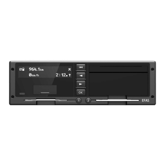
Chapter 4 Control elements and displays The EFAS smart tachograph The EFAS smart tachograph has a two-line LCD display, two slots for tachograph smart-cards, a front-mounted interface for calibration and downloading, a printing module, and 6 operating keys. It can be installed in a standard-sized car stereo slot. Warning alerts can be emitted optically and acoustically. -
Page 19: Card Readers
Meaning Description Referred to in the text below as: v Key for driver 2 By briefly pressing the button, the driver activity (working time, standby time and rest time) can be selected for driver 2. The activity only cycles to the next one after the key is released. Pressing the key for at least 1.5 seconds when the vehicle is stationary requests the card to be ejected from slot 2. -
Page 20: Warning Light And Acoustic Signals
Text is displayed in the local language as configured. The language is set based on the local language of the driver’s or workshop smart-card or it can be selected via the main menu. Warning light and acoustic signals The red warning light displays various operating states of the EFAS smart tachograph. In the default configuration, certain operating states are indicated with an acoustic signal. -
Page 21: Service Port
Figure 5 — Printer paper container Details on removing the printer paper container and inserting the printer-paper roll are available in section 7.6. Service port The service port located on the front panel of the EFAS smart tachograph is covered with a rubber cap. The port has two inde- pendent components;... -
Page 22: Working With Menus
Working with menus Making selections in the menus and sub-menus of the EFAS smart tachograph is effected using the operating keys. The following instructions show you how you can work with the menus. Menus can only be accessed when there are no messages or alarms being displayed and the vehicle is stationary. Acknowledge any warnings with OK to see the standard display. -
Page 23: Card Combinations And Their Effect On The Operating Mode
Note The EFAS smart tachograph will ignore invalid tachograph smart-cards. However, it is possible to display, print and download the data stored on cards that have expired. An invalid or expired tachograph smart-card will be indicated by the symbol instead of the card symbol. 4.9.1 Card combinations and their effect on the operating mode The following table shows the mode of operation of the EFAS smart tachograph depending on the tachograph smart-cards... -
Page 24: Chapter 5 General Instructions Prior To Installation
Please also check before installation that the unit is in factory condition and whether the installed software is up to date. The software must be approved by the manufacturer, Intellic GmbH, and certified by the official EU approval bodies. The certified hardware and software versions are available at the following link: https://www.bsi.bund.de/zertifizierungsreporte... -
Page 25: Details On The Type Label
The company Intellic maintains a list of products and their versions. A product code is specified for every new product or product version. The product-group labeling for EFAS is “E5T“. The EFAS serial number begins with this. The device version is specified as a decimal with the next 3 digits. -
Page 26: Chapter 6 Installing And Commissioning
Chapter 6 Installing and commissioning This chapter describes how the EFAS smart tachograph is installed in a vehicle and how EFAS is put into operation. The main steps are the activation of the tachograph and its pairing with a motion sensor. Checks before installation Prior to installation of the EFAS smart tachograph in a vehicle, check that the type label and the seal are intact. -
Page 27: Pin Assignment For The Device
Figure 9 — Connector panel Warning The lines A5 and A6 must be wired for the correct operation. If the line A6 is not wired in the vehicle-side con- nector cable, a connection (bridge) between A5 and A6 must be produced. Affected are especially vehicles with 12 V power supply. -
Page 28: Protection Of Positive And Negative Pole
Contact Direction Function Comment Cable cross-section - - - Not used CAN_H (C) High-signal CAN bus C, 0.35 - 1 mm CAN_GND (C) Ground CAN bus C 0.35 - 1 mm CAN_L (C) Low-signal CAN bus C 0.35 - 1 mm CAN (C) 120 Ω... -
Page 29: Conditions For Switching-On And Operating States
Insert the tachograph into the intended bay until you hear the clips click into place. 6.2.5 Conditions for switching-on and operating states The EFAS smart tachograph is activated by the following signals (conditions for switching on): Connection to the power supply Switch on the ignition Card insertion Key-press... -
Page 30: Installing The Battery
Figure 11 — Battery replacement, step1 Use a screwdriver (TORX, T10) to remove the M3x6 screw. This releases the seal holder from the base plate. Make sure that the screw and the seal holder do not get lost. Figure 12 — Battery replacement, step 2 Slide the cover gasket backwards over the wiring harness. -
Page 31: Seals
Pressing on both sides, slide the base plate backward until it clicks into place. Insert the black seal holder into the recess in the base plate and use the M3x6 screw to secure the base plate. Punch a seal with your workshop’s lead sealing pliers and then press it into the seal holder until you hear it click into place. Slide the cover gasket back over the device and insert it again correctly from the back into the EFAS front panel. -
Page 32: Figure 16 - "Welcome" Message
Figure 16 — "WELCOME" message Following the “WELCOME“ message, the following text is displayed for 3 seconds (see figure below). The local language depends on the settings made when the device was configured. Unless the tachograph has been activated, pressing the keys or and u and v for three seconds will display a message saying that the device has not yet been activated. -
Page 33: Figure 21 - Prompt For Pin Input
Note If no key is pressed within 30 seconds, an approximately 5 second acoustic warning signal will sound that can be acknowledged with the 9 key. The PIN input prompt will then be displayed continuously until the input is aborted using the keypad or until the vehicle starts moving. Figure 21 —... -
Page 34: Sample Printouts "Technical Data
to the motion sensor to form a functional unit. Figure 27 — Activation The automatic pairing only takes place when a workshop smart-card is inserted for the first time. If not motion sensor is con- nected the tachograph will be activated and, when the smart-card is removed, an error message will be displayed indicating that the pairing process failed. -
Page 35: Before Activation
6.4.1.1 Before activation The printout “Technical data” of the EFAS does not refer to a calibration purpose. There is no information regarding the sensor. - Time of printout - Expression type: Technical data - Information on the VIN consists of “?” - Member State empty / Vehicle registration plate consists of “?”, if no information was provided on this before activation;... -
Page 36: Initial Installation
6.4.1.3 Initial Installation After the data for the first installation have been entered and the workshop card has been removed, the parameters are transferred to the EFAS. The printout “Technical data” now shows the calibration purpose (2) “Initial installation”. - Vehicle identification number - Calibration purpose (2) „Initial calibration“... -
Page 37: Calibration
6.4.1.4 Calibration After initial installation, the tachograph is calibrated for the first time. At this time only the unknown data “Vehicle registration number” and “Member State” are missing. - Vehicle Identification Number - Calibration purpose (4) „Installation” - Vehicle characteristic w-factor - Real tyre circumference - Nominal tyre size - max. -
Page 38: Entry Of The Registration Number By The Vehicle Holder
6.4.1.5 Entry of the registration number by the vehicle holder Once the vehicle holder has registered the vehicle and the license plate number and the registering Member State have been established, these previously unassigned details can be added to the calibration data. -
Page 39: Figure 30 - Sensor Pairing Commences
pairing process can take up to three minutes. When using a calibration device, it generally displays information on the progress and success of the motion sensor pairing process. If you use the EFAS Service Tool you will receive all necessary information on the progress and success of the pairing process as well as key data of the paired motion sensor on the computer running the EFAS Service Tool. -
Page 40: Installing The Dsrc Module
Installing the DSRC module To enable the remote communication function, the EFAS-4.10 DSRC Unit must be connected to the EFAS Smart Tachograph. This enables employees of the responsible control authorities to read tachograph information from passing vehicles. 6.6.1 Installation of the DSRC module according to EU regulation 2016/799 The module shall be placed in or near the centre of the windscreen of the vehicle. -
Page 41: Chapter 7 General Settings
Chapter 7 General settings The following general settings for EFAS can be changed with the menu: y Times format on the printouts y The display’s appearance y Acoustic signals y Time and date y Company lock y Automatic activity setting after ignition OFF/ON y Time before warning when speed limit is exceeded (>>... -
Page 42: Time Zone
Sunday in March and the last Sunday in October if the summertime parameter is set to AUTO (automatic). The UTC time of the internal clock is not changed. 7.1.2 Time zone The time-zone setting specifies the constant that is added to UTC time to display the local time. The value can be modified in steps of 30 minutes. -
Page 43: Automatic Activity Setting After Ignition Off/On
Automatic activity setting after ignition OFF/ON EFAS is able to activate a preprogrammed activity (, or ) for the driver and/or co-driver when the ignition is turned on or off. Programming of the activities after ignition OFF/ON is only possible in the COMPANY or CALIBRATION operating modes, i.e. with a company smart-card or workshop smart-card inserted. -
Page 44: Removing The Printer Paper Container And Inserting The Printer Paper Roll
Remote download of driver smart-card data to the company server Remote download of mass memory data (vehicle data) Removing the printer paper container and inserting the printer paper roll This section explains how to remove the printer module in order to be able to insert a new paper roll. Hazard Only change printer paper when the vehicle is safely parked. -
Page 45: Chapter 8 Parameter Configuration
Chapter 8 Parameter configuration In addition to the legally required calibration parameters described in Chapter 9, the smart tachograph EFAS supports addi- tional parameters that can be set via the service port. The advanced parameters allow for adaptations to different types of vehicles, and additional functions supported by the EFAS smart tachograph can also be configured. -
Page 46: Nominal Voltage Of The Vehicle (On-Board Power Supply) (Rdi=0Xfda3)
Parameters for vehicle adaptation Settings/value ranges AUTO Wake-up via CAN-bus Wake up from standby not possible FD6D Wake-up via CAN message possible Source to reset the trip distance Reset via the CAN bus FD00 Reset via the tachograph menu (keypad) Configuration of lighting control Set brightness of EFAS by menu and pin A2 FD34... -
Page 47: Can-Bus Configuration Of The Auxiliary Can Expansion Bus (Can Aux)
8.3.3 CAN-bus configuration of the auxiliary CAN expansion bus (CAN AUX) This CAN bus is provided for additional functions such as connecting to remote data transfer equipment or to the DSRC module.. Configuration of the CAN bus and the role of certain CAN parameters is described separately in section 13.1. 8.3.4 Wake-up via CAN-bus (RDI=0xFD6D) This parameter determines whether the tachograph can be activated by messages on the CAN interface with the ignition off... -
Page 48: Selection Of Engine-Speed Data Source (Rci=0Xfd3A)
many calibration/programming devices do not allow for entries after the decimal point, so that the values require multiplication by a factor of 1000. Typical settings are: 0.001 pulses/rev, 5.796 pulses/rev, 6.000 pulses/rev, 8.000 pulses/rev, 8.138 pulses/rev, 10.000 pulses/rev , 12.217 pulses/rev Warning An incorrect parameter setting can lead to malfunction or damage to the transmission and other serious dis- turbances of the driving and braking functions. -
Page 49: Automatic Parameters Detection
Automatic Parameters Detection The smart tachograph is able to make a useful setting for some parameters by itself. The parameters that can be set automati- cally, are listed and marked in Table 10. The “automatic parameter detection“ function may be started via EFAS menu. It is highly recommended to start it only when the EFAS is installed within a vehicle, the ignition is switched on and a valid workshop card is inserted. -
Page 50: Chapter 9 Calibration
Chapter 9 Calibration EU Regulation 165/2014 defines the calibration of the smart tachograph as an update or confirmation of vehicle parameters, including the vehicle identification and vehicle characteristics to be stored in the mass memory, by use of the workshop card. Calibration must be performed following the installation of the EFAS device into the vehicle as part of its activation and also during its regular inspections. -
Page 51: Data Read-Out
Plausibility of the data on the installation plaque Proper condition of the seals (smart tachograph, sensor/tacho shaft and all removable electrical and mechanical connections) Proper condition of the lines between the tachograph and motion sensor The components of the smart tachograph being intact (missing components, foreign objects, etc.) If the line to the motion sensor cannot be visually checked for manipulation, it is possible to open the seals and lay a temporary line between both components and to perform a quick functional inspection on the smart tachograph EFAS. -
Page 52: Prüfung Des Gnss-Moduls
The calibration requires a valid workshop card and the corresponding PIN. The determined calibration values are stored in the device after the workshop card has been removed. However, the calibration, i.e. the determination of the values must always take place with approved calibration equipment. Prüfung des GNSS-Moduls Zur Prüfung des GNSS-Moduls siehe Abschnitt 10.6.15. -
Page 53: Chapter 10 Fault Diagnosis
Chapter 10 Fault diagnosis 10.1 Events, malfunctions, and operating instructions in general The smart tachograph EFAS monitors all relevant system functions of the tachograph system cyclically. This includes the smart tachograph EFAS itself with individual components such as printer, keyboard, display unit and card slots as well as the motion sensor connected and the instrument panel connected via the CAN bus. -
Page 54: Display Of Events And Malfunctions
Regardless of the type, all events and malfunctions of the EFAS are assigned to a “Service-ID” (aka SrvID) defined by the tacho- graph manufacturer Intellic. The relationship between the separate types is clearly established via the service ID. Moreover, there are additional codes that have been defined by the tachograph manufacturer and for which there is no equivalent code of type 1 or type 2. -
Page 55: Displays In The Calibration Mode And Before Activation
Explanation of the display: SrvID:S70 Service identifier (service ID number) Number of unacknowledged messages of the same type 22.06.19 12:03 Time and date of the first occurrence (#1) of the message DTCs are output on the display unit only if they are identical to events or malfunctions of type 1. For this purpose, use a suitable diagnostics device or the EFAS Service Tool to ensure that DTCs are stored in the device. -
Page 56: Tools For Error Diagnosis
Tools for error diagnosis You can use test equipment or the EFAS Service Tool available from Intellic as a fault diagnosis tool. The EFAS Service Tool is a program that can be executed under the Microsoft operating system Windows on a desktop PC or a notebook. -
Page 57: Printer Test
mode. The test functions are described separately in the following chapters. Note Please note that the test functions listed are either not supported or supported only partially by test instruments that are commercially available. If necessary, ask the test instrument manufacturer for updated software of the test instrument that you use. -
Page 58: Display Unit Test
10.6.4 Display unit test The display unit test requires an optical inspection of the display. For this purpose, black squares, similar to a chessboard pattern, are displayed alternately, so that all image points (pixels) are controlled in an alternating manner. Based on the display observed, it can be verified whether all pixels are displayed correctly. -
Page 59: Testing The Warning Lamp And The Acoustic Alarm
DTC (hex) Meaning 80 00 000004 Interruption of power supply to the tachograph 80 00 002180 Malfunction of the pulse signal of the motion sensor / speed sensor 80 00 002380 Malfunction in data communication to the motion sensor / speed sensor 80 00 000800 Malfunction in the clock or invalid time/date 40 00 000A70 The CAN bus signals an internal malfunction (only affects the bus at the A plug connector) 40 00 000B78 The CAN bus is in the “Bus Off”... -
Page 60: Testing For Digital Inputs/Outputs At The Connector Panel
10.6.10 Testing for digital inputs/outputs at the connector panel This test function is used to inspect the digital inputs and outputs at the connector socket of the EFAS. The wiring at the con- nector socket and the connection to the devices attached can be checked in this manner. The logical signal level (value “0” or “1”) is displayed for the inputs light/lighting (pin A2), for the ignition signal (pin A3), for the status inputs (pins D1 and D2) and for the warning signal output (pin D4). -
Page 61: Gnss Test
10.6.15 GNSS Test The GNSS test function can be started in the CALIBRATION operating mode via the menu. The test function indicates whether the GNSS function is functioning properly. 1. Select OK g Installation g GNSS Test 2. Browse to the appropriate information using the control buttons and . 3. -
Page 62: Can Test
10.6.17 CAN Test With the EFAS Service Tool the communication on CAN A and CAN C can be checked. Workshop Manual Digital Tachograph EFAS-4.10... -
Page 63: Chapter 11 Repair Options
Chapter 11 Repair options If the smart tachograph EFAS is damaged mechanically or if the keyboard or the display is defective, then the smart tachograph must be replaced completely. Cards which have become stuck can be removed from the device. 11.1 Removing the tachograph Proceed as follows to remove the EFAS tachograph from the vehicle. -
Page 64: Replacing The Buffer Battery
Note Please take care not to inadvertently eject your workshop smart-card. If this should still happen, please mark the event in the protocol. The card that has jammed is ejected. Check the ejected card for contamination or mechanical damage. Also check if the card slot is dirty or whether foreign objects are inside. -
Page 65: Warranty
11.6 Warranty The manufacturer Intellic offers a two-year warranty period starting with the first activation of the device on all devices. Any operation on the device other than that mentioned above leads to the warranty being rendered invalid. When you send a device back to the manufacturer for repair, please enclose a detailed fault description along with it. -
Page 66: Chapter 12 List Of The Events/Malfunctions And Measures For Trouble-Shooting
Chapter 12 List of the events/malfunctions and measures for trouble-shooting Abbreviations and explanations: SrvID Service ID (EFAS service code) Event fault type, error code in accordance with EU Regulation (EC) No. 2016/799 Diagnostic trouble code (standardized automotive error code) Decimal (base 10 numeral system) Hexadecimal numeral system with a base of 16 (using characters 0 to 9 and A to F) 12.1 EFT summary table... -
Page 67: Overview Of Service Ids
Meaning SrvIDs (hex) 0x24 Unauthorized opening of the housing 0x25 Hardware sabotage 0x3x Vehicle unit error 0x30 No further details 0x31 Vehicle unit internal error S35, S41, S42, S43, , S48, S81, S87, S92, S94, S95, S96, S97, S98, S99, S103, S105, S108, S110, S111, S112, S113, S114, S119 0x32 Printer error 0x33 Display error... - Page 68 SrvID Symbol Description and trouble-shooting Display text 80 00 002004 ! Interruption Meaning / Cause: An interruption of the supply voltage of the motion sensor of power supply longer than 200 ms has been detected and reported by the motion sensor. Measures: Measure the supply voltage of the motion sensor at the pins B1 and B2.
- Page 69 SrvID Symbol Description and trouble-shooting Display text 40 00 000200 ! Card Meaning / Cause: An invalid card has been inserted in the card slot 1. invalid The following causes are possible: The card has been inserted the wrong way round. (Symbol in the display for The card is not a tachograph card.
- Page 70 SrvID Symbol Description and trouble-shooting Display text 40 00 000200 ! Last use of card Meaning / Cause: A tachograph smart-card has been inserted into card slot 1 after not finished the card was previously inserted in another tachograph and was not closed down properly.
- Page 71 SrvID Symbol Description and trouble-shooting Display text 40 00 000200 ! Security Meaning / Cause: An error was detected while authenticating a tachograph card violation in card slot 1. In the case of this error it is unlikely that there is a defect in the card locking mechanism or the card reader of EFAS, since, in this cases other error codes are reported.
- Page 72 SrvID Symbol Description and trouble-shooting Display text 80 00 002380 ! Sensor data Meaning / Cause: The communication via the data channel (pin B4) between the error tachograph and the motion sensor is interrupted. The motion sensor is not responding or no motion sensor is connected. Measures: Connect and pair the motion sensor, if not yet done.
- Page 73 SrvID Symbol Description and trouble-shooting Display text 80 00 000800 ! Security Meaning / Cause: The tachograph has an error in the current time or has detected violation a malfunction in the integrated clock. Further data recording and finally is no longer possible. Data recording is not continued in order Service! to avoid inconsistent data.
- Page 74 SrvID Symbol Description and trouble-shooting Display text 40 00 000A70 - - - Meaning / Cause: Communication on the CAN main vehicle bus (depending on the parameter setting at the A or C connector) of EFAS has mal- functioned or is not possible. The following causes are possible: No bus subscriber is connected or a bus subscriber is not supplied with voltage.
- Page 75 SrvID Symbol Description and trouble-shooting Display text 40 00 001177 - - - Meaning / Cause: The communication with the instrument panel / E-tachometer has malfunctioned or is interrupted. The connection between the instrument panel / E-tachometer and EFAS is monitored by the tachograph cyclically by means of a life sign message trans- mitted by the instrument panel / E-tachometer every second.
- Page 76 SrvID Symbol Description and trouble-shooting Display text 80 00 000D40 - - - Meaning / Cause: The calibration data are incorrect or incomplete at the end of a calibration procedure (e.g., after pulling out the workshop smart-card). At least one of the EC calibration parameters does not have a valid value or during the calibration procedure, setting a given value was rejected and finally not corrected.
- Page 77 SrvID Symbol Description and trouble-shooting Display text 40 00 000F00 Internal Device Meaning / Cause: Malfunction of the keyboard has been detected, i.e. at least one malfunction key remains continuously pressed. The tachograph assumes that a key has been pressed continuously if it remains pressed for more than two minutes.
- Page 78 SrvID Symbol Description and trouble-shooting Display text 80 00 001260 ! Driving without Meaning / Cause: The vehicle was moved although there was no valid tachograph a suitable card smart-card (driver’s card or workshop smart-card) inserted into card slot 1. Measures: Check whether a valid driver’s card or workshop smart-card has been inserted in card slot 1.
- Page 79 SrvID Symbol Description and trouble-shooting Display text Download Meaning / Cause: There is a malfunction while downloading data. malfunction Measures: Check the connection (cable and connector) to the front interface of the recording equipment. Check if the transmission equipment used is compatible with the recording equipment (check the manufacturer and software version used on the transmission equipment).
- Page 80 SrvID Symbol Description and trouble-shooting Display text 40 00 002280 ! Vehicle motion Meaning/Cause: EFAS has detected a relevant difference between the speed conflict values of the paired motion sensor and the speed rvalues of the SrvID: S83 GNSS receiver. According to CR (EU) 2016/799, a speed difference between these two motion sources is classified as relevant if the median value of the deviation is continuously above 10 km/h for 5 minutes in...
- Page 81 SrvID Symbol Description and trouble-shooting Display text 40 00 00FD0B This malfunction matches SrvID S33, however, it relates to the - - - CAN expansion bus. 40 00 000200 ! Security Meaning / Cause: The integrity (authenticity) of the data on the tachograph card in violation card slot 1 is not assured.
- Page 82 SrvID Symbol Description and trouble-shooting Display text 40 00 000139 Internal device Meaning / Cause: A general internal device malfunction is at hand. EFAS has per- malfunction formed a restart as a consequence of an extraordinary event during program execution. Measures: If this fault continues to occur, the tachograph must be replaced.
- Page 83 SrvID Symbol Description and trouble-shooting Display text S107 Meaning / Cause: ! Manufacturer- Protocol entry after a software update. An update of EFAS oper- specific event ating system software is recorded with this event. Measure: None S108 40 00 000139 Internal device Meaning / Cause: The data of the battery-backup memory has been lost.
- Page 84 SrvID Symbol Description and trouble-shooting Display text S114 40 00 000139 Internal device Meaning / Cause: The temperature control of the EFAS is faulty or the temperature malfunction is too low. Measure: If this error occurs at normal temperature the tachograph has to be replaced.
- Page 85 SrvID Symbol Description and trouble-shooting Display text S132 Meaning / Cause: ! dd.mm.yy Is displayed xx days before the card expiry date (dd.mm.yy), Card expiration date where xx is determined by the parameter RDI = F993 (default = (slot 1) 60 days).
- Page 86 SrvID Symbol Description and trouble-shooting Display text S170 GNSS Meaning / Cause: The tachograph receives no data from the internal GNSS receiver. error Measure: If the error is still displayed after several ignition cycles, the GNSS receiver is not functioning properly and the tachograph must be replaced.
-
Page 87: Dtc Overview Table
SrvID Symbol Description and trouble-shooting Display text S200 > Input error < Meaning / Cause: see SrvID:S200 With manual input of the driver’s activities the maximum number of 20 activity changes per shift has been exceeded. S201 > Company lock < Meaning / Cause: see SrvID:S201 Company lock cannot be activated or deactivated as another,... - Page 88 Meaning Service ID (hexadecimal) 80 00 000007 The supply voltage of the recording equipment is above the maximum permissible value 80 00 000003 The supply voltage of the recording equipment is below the minimum permissible value 80 00 000004 Interruption of the supply voltage to the recording equipment 40 00 000200 Card error in slot # 1 S7, S9, S11, S13, S15, S19, S39, S90, S117,...
-
Page 89: Printout Of Service Ids
Meaning Service ID (hexadecimal) 40 00 C25900 Communication error with remote communication S173, S174 equipment (DSRC) 40 00 C46B00 Missing position data of the GNSS receiver S171 40 00 F01762 Time conflict (between GNSS and EFAS system clock) 40 00 000B80 VW CAN Time-Out Dimmung 01 S177 40 00 000D80 VW CAN Time-Out GW 71 S176... -
Page 90: Support During Installation And Operation Of The Tachograph
Press the F5 function key or select the Create Support File... function from the Tools menu. In the PIN dialog box, enter the PIN received from the intellic support team and choose OK. If the creation of the support file was successfully completed, the corresponding folder can be opened or displayed via the active button Open Output Folder in Explorer …... -
Page 91: Chapter 13 Interfaces
Chapter 13 Interfaces 13.1 CAN bus The following chapters provide an overview of the various CAN interfaces at the A and C plug connectors, the types of data transfer possible via CAN bus and relevant CAN parameters. 13.1.1 Overview The EFAS smart tachograph has two independent CAN interfaces. One CAN bus (the main vehicle bus) is intended for the exchange of data with an instrument panel or an electronic tachometer, as well as for the connection of diagnostic devices. -
Page 92: Data
The EFAS test functions for the CAN bus (CAN A Test and CAN C Test) can support the determination of the correct termination. CAN A On delivery, EFAS is connected to CAN bus A, i.e. the terminating resistor is switched in. To remove the terminating resistor on CAN bus A, use a suitable tool to remove the integrated fuse on the EFAS connector panel. -
Page 93: Can Parameters
13.1.4 CAN parameters If the A plug connector’s CAN bus is to be used, a number of parameters must be set, so that the CAN bus fulfills the specific requirements of the respective vehicle type. The following functions are set with these parameters: Transmission rate (125 kbps, 250 kbps or 500 kbps) Length of CAN identifier (11 bits or 29 bits) Protocol selection “Standard protocol”... -
Page 94: Serial Interfaces D7 And D8
Table 20 — Manufacturer-specific CAN parameters CAN A / CAN C parameters Ranges of values RDI hex Selects the CAN main vehicle bus CAN main vehicle bus on connector A FD6E CAN main vehicle bus on connector C Basic configuration, A bus (bit rate and ID length setting) ON/OFF, 11/29 bit FD01 250 kbps or 500 kbps... -
Page 95: Protocol, Information Interface
with K-line interface if the vehicle in which EFAS is to be installed does not have a CAN bus for connecting the tachometer/ instrument cluster to the tachograph. 13.2.1 Protocol, information interface According to (EC) regulation no. 1360/2002, margin no. 153, the smart tachograph must have an interface for cyclical data transmission. -
Page 96: Distance Encoding Output B8
The selection is made with a suitable inspection device or with the EFAS Service Tool. 13.3.3 Distance encoding output B8 At its output B8, EFAS encodes the distance travelled by providing one pulse per 0.25 m of distance travelled, so this output is also referred to as a “4 pulse/m”... -
Page 97: Chapter 14 Additional Data Recording
Chapter 14 Additional data recording EFAS facilitates the recording of additional data. Unlike mass memory data, which is required as per (EC) regulation 2016/799, this data can be deleted from the mass memory. There is still no obligation to archive this data. EFAS can additionally record the following data: Vehicle speed (v profile), Engine speed (n profile) -
Page 98: Logging The Two Status Inputs D1 And D2
The source can be configured with the EFAS Service Tool or a suitable testing / calibration device. In addition, at source C3, it is necessary to set a parameter - the so-called n-factor - with which EFAS can calculate an engine speed from the pulse frequency. Figure 69 —... -
Page 99: Chapter 15 Driver's Times Summary ( Icounter )
Chapter 15 Driver’s times summary ( iCounter ) The print out of current driving times can be done using the print function „ Driver’s times summary“. Remarks: y A question mark (“?”) is printed after a value when periods of unknown activity were consulted in order to calculate breaks an d rest periods. -
Page 100: Chapter 16 Updating The Efas Operating Software
(described in the following) must be adhered to in order to update the tachograph software. The software update must be approved by the manufacturer, Intellic GmbH, and certified by the official EU approval bodies. The certified hardware and software versions are available at the following link: https://www.bsi.bund.de/zertifizierungsreporte... -
Page 101: Finishing The Software Update
In this case the display shows “PIN incorrect” and the EFAS Service Tool displays a corresponding error message “Software update failed”. Note Check with our distributors or our Internet portal (www.intellic.com) to see if an update for the tachograph application is available for the EFAS smart tachograph. Workshop Manual... -
Page 102: Chapter 17 National / Regional Abbreviations And European Time Zones
Chapter 17 National / regional abbreviations and European time zones The following table provides an overview of national and regional abbreviations, as well as time zones: Table 21 — National / regional abbreviations and European time zones Nation Abbreviation Time zone offset (without DST) Albania +01:00h Andorra... - Page 103 Nation Abbreviation Time zone offset (without DST) Catalonia +01:00h Castilla y León +01:00h Castile-La Mancha +01:00h Valencia +01:00h Extremadura +01:00h Galicia +01:00h Balearic Islands +01:00h Canary Islands +01:00h La Rioja +01:00h Madrid +01:00h Murcia +01:00h Navarre +01:00h Basque Country +01:00h Sweden +01:00h Switzerland...
-
Page 104: Chapter 18 Technical Data
Chapter 18 Technical data The following table contains the EFAS smart tachograph’s most important technical data: Table 22 — Technical data Technical data Nominal power supply 12 V (typ. 13.8 V) or 24 V (typ. 27.0 V) Power supply range 8 V to 32 V (for max. -
Page 105: Chapter 19 Menu Structure In Efas
Chapter 19 Menu structure in EFAS The following figure depicts the EFAS menu structure Figure 73 — EFAS menu structure Figure 73 is a representation of the menu structure in EFAS. Which of the menu items can be accessed depends on the operating mode as set by inserting certain types of tachograph smart-card. -
Page 106: Chapter 20 Symbols And What They Mean
Chapter 20 Symbols and what they mean This chapter provides an overview of all symbols and symbol combinations used by the EFAS smart tachograph in on-screen displays, or in printouts. 20.1 Persons, activities and operating modes Table 23 — Symbols for persons, activities and operating modes Symbol Person Activity... -
Page 107: Special Conditions
Symbol Devices Vehicle / vehicle unit GNSS-facility Equipment for remote communication ITS-interface 20.5 Special conditions Table 27 — Symbols for special conditions Symbol Specific conditions Recording equipment not required Ferry crossing / rail travel 20.6 Miscellaneous Table 28 —... -
Page 108: Time Intervals
20.8 Time intervals Table 30 — Symbols for time intervals Symbol Interval Daily Weekly Fortnightly From or until 20.9 Symbol combinations Table 31 — Symbol combinations Symbol Meaning Control location (manual specification) Location at the start of the working day ... -
Page 109: 20.11 Printouts
Symbol Meaning Fortnight’s driving time II 20.11 Printouts Table 33 — Symbols for printouts Symbol Meaning Daily driver activity printout from the smart-card 24h Daily driver activity printout from the internal memory 24h Printout of events and malfunctions from the smart-card !... -
Page 110: 20.14 Marking Of Manual Entries
Symbol Malfunction Internal device malfunction in the smart tachograph GNSS fault DSRC fault 20.14 Marking of manual entries Table 36 — Symbols for marking the driver’s manual entries Symbol Entry Manual entry of driver activities for the smart-card in the driver’s card slot ... -
Page 111: List Of Abbreviations
List of abbreviations Abbreviation Description Adaptive Cruise Control Controller Area Network Decimal (base 10 numeral system) Daylight-saving time Diagnostic trouble code (standardized automotive error code) DSRC Dedicated Short Range Communication European Community Electronic control unit Event fault type, error code in accordance with EU Regulation (EC) No. 1360/2002 End of line European Union Fleet Management System... -
Page 112: List Of Figures
List of figures Figure 1 — Keys............................................8 Figure 2 — Card readers ........................................9 Figure 3 — Alphanumeric display ....................................9 Figure 4 — Red warning lights to display the operational status ........................10 Figure 5 — Printer paper container ....................................11 Figure 6 —... - Page 113 Figure 62 — Testing the rotational speed of the output shaft..........................50 Figure 63 — Display of measurements for the motion sensor interface ......................50 Figure 64 — Display of the back-up battery voltage..............................50 Figure 65 — Position of the card readers release lever ............................53 Figure 66 —...
-
Page 114: List Of Tables
List of tables Table 1 — Warning light and acoustic signals ................................10 Table 2 — Pin assignment of the service port ................................11 Table 3 — Operating modes - symbols ..................................12 Table 4 — Operating modes from tachograph smart-cards..........................13 Table 5 — Housing dimensions .....................................16 Table 6 —... -
Page 115: Index
Index European Union regulations Event messages Access rights Events Acoustic signals Exceptions from the obligatory use Activating the recording equipment exceptions to the compulsory use Activities Exclusion of warranty AETR agreement Automatic activity setting after ignition OFF/ON Automatic Parameters Detection Factor for calculating the speed Factory settings Fault diagnosis... - Page 116 National abbreviations Test drive National regulations Test equipment Nominal voltage of the vehicle Test functions Testing for digital inputs/outputs Testing the acoustic alarm Testing the engine-speed signal source Operating instructions Testing the internal battery Operating states Testing the motion sensor interface Output Shaft Speed Testing the on-board power supply Overview of Service IDs...
Need help?
Do you have a question about the Bosch EFAS-4.10 and is the answer not in the manual?
Questions and answers