Table of Contents
Advertisement
Quick Links
Advertisement
Table of Contents

Related Manuals for Jegs 86008


Summary of Contents for Jegs 86008
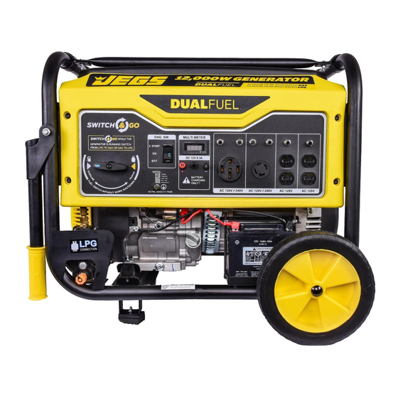
- Page 1 User Guide for 86008 Generator 12,000 Watt, Rated 9,500 Watt Dual-Fuel...
-
Page 2: Table Of Contents
Table of Contents Parts List...............2 Moving the Generator........15 Do Not Overload Generator........15 Introduction............3 Wattage Reference Guide.......16 Product Specifications........3 Hour Meter............17 Customer Service ..........3 Power Management........17 How to Charge a Battery........17 Safety Rules............3-6 Cold Weather Operation........17 Safety Symbols..........3 Maintenance..........18-21 Safety Instructions..........4-6 Maintenance Schedule........18 Assembly............07-11 High Altitude Operation........18... -
Page 3: Parts List
Parts List 20 21 Fuel Selector Switch Tank Vapor Valve Air Filter Housing On/Off Switch Fuel Gauge Handle & Grip Hour Meter Fuel Fill Cap Support Leg Circuit Breaker Fuel Tank Oil Drain Plug 12V 8.3 Amp Output Generator Frame Oil Fill (Dipstick) 120/240V AC 50 Amp Receptacle Choke Lever... -
Page 4: Introduction
Thank you for purchasing this 12000 watt portable Save your original sales receipt and record the generator from JEGS. This generator is designed to following information below for service or warranty give you years of reliable service when operated and assistance. -
Page 5: Safety Rules
Safety Rules The engine exhaust contains chemicals The manufacturer cannot anticipate every possible circumstance that the user may encounter hazards. that can cause cancer and birth defects. Therefore, the warnings in this manual, on tags, • Always wash hands after handling generator. and on affixed decals are not all-inclusive. - Page 6 Safety Rules Cont. Keep away from flammable objects Avoid touching hot areas of this unit. and other hazardous materials. • Only operate the generator on a level surface. • The fuel and its vapors used to power this unit • If connected to a structure, connect the ground are highly flammable and could explode resulting terminal to an appropriate ground.
- Page 7 Safety Rules Cont. Only use as intended. Used incorrectly serious injury or death could result. • Do not bypass any safety device. Moving parts are covered with guards. Make sure all protective covers are in place. • Never transport or make adjustments to this unit while it is running.
-
Page 8: Assembly
Assembly Unpacking Handle Assembly 1. Place box on a level surface. 2. Remove all items from box except the generator. Make sure all items listed on the packing list are included and not damaged. 3. Cut down the sides of the box being careful to avoid hitting the generator. - Page 9 Assembly Cont. Attaching the Handle (Figure 1) 1. Parts needed: • 2 Handles • 2 Bolts • 2 Nuts • 4 Washers 2. Install washers into handle bracket. 3. Install handle bracket to generator frame. 4. Insert bolt and tighten nut until secure. Figure 2 Figure 1 Installing the Support Legs (Figure 3)
-
Page 10: Battery Install & Warnings
Assembly Cont. Attaching Battery Cable (Figure 4) Battery posts, terminals, and accessories contain lead and lead compounds known 1. Locate the pigtail harness already attached to to cause cancer and reproductive harm. the battery (-) negative post. • Always wash hands after touching the battery. 2. -
Page 11: Assembly
Assembly You must add oil before first operating Adding Fuel (Figure 6) this generator. Check level every use. 1. Set the generator outdoors away from windows • DO NOT use E15 or E85 fuel in this unit. It is a and doors. -
Page 12: Connecting Generator To A
Assembly Cont. generator in rain or under wet conditions. • Use a ground fault circuit interrupter (GFCI) in a damp or highly conductive area, such as metal decking or steel work. • Never plug electronic devices into generator having frayed, worn, or bare wires. Never touch bare wires or make contact with receptacles. -
Page 13: Operation
Operation Grounding the Generator (Figure 7) How to Start the Engine (Figure 8-13) This portable generator is equipped with a terminal Place generator on a level surface. All electrical loads for the connection of a ground electrode conductor MUST be disconnected from generator. where a grounding electrode system is required by NEC Article 250.34(A). -
Page 14: Adding Electronics
Operation Cont. Never start or stop engine with electrical for more than 15 seconds. Allow 1 minute between each starting attempt. devices plugged in to the receptacles. • For manual start, turn the engine Start switch Failure to do so could damage the generator and / or connected electrical devices. -
Page 15: Receptacles & Extension Cords
Operation Cont. 120 Volt AC, 20 Amp receptacle • This receptacle has a 20 Amp push-to reset circuit breaker to protect against overload. • Each socket is rated to operate 120 Volt, AC, single phase, 60Hz loads requiring up to 2400 watts (2.4 kW) at 20 Amps. -
Page 16: Extension Cord Selection
Operation Cont. Current Load (Watts) Maximum Cord Length (Feet) (Amps) 120V 240V #8 Wire #10 Wire #12 Wire #14 Wire #16 Wire 1,000 1200 1800 1200 2400 1800 3800 2400 4800 3000 6000 3600 7200 Extension Cord Selection Don’t Overload the Generator Refer to the above table to ensure the extension cord Make sure you can supply enough rated watts and used has the capacity to carry the required load. -
Page 17: Wattage Reference Guide
Operation Cont. Operating Voltage and Frequency Kitchen Rated Watts Surge Watts 1500 Electric Range (1 element) 1500 Operating voltage and frequency requirement of Dishwasher 1500 2000 all electronic equipment should be checked prior 3500 Electric Oven 3500 to plugging them into this generator. Damage may result if the equipment is not designed to operate Electric Water Heater 4000... -
Page 18: Hour Meter
Operation Cont. Never exceed generator’s wattage/ if they are corroded. amperage capacity. This could damage • Connect the Battery Charging Cable to the 12 the generator and connected electrical devices. Volt DC posts. • Connect the red cable clamp to the positive (+) •... -
Page 19: Maintenance
Maintenance Regular maintenance will extend the life of this After first 5 Change engine oil generator and improve its performance. The warranty Hours does not cover items that result from operator abuse, After 8 Hours Clean debris from generator misuse, or negligence. To receive full value from the or Daily and air filter area warranty, operator must maintain the generator as... -
Page 20: Checking Spark Plug
Maintenance Cont. Oil Recommendations • Do not use special additives. • Outdoor temperatures determine the proper oil viscosity for the engine. Use the chart to select the best viscosity for the outdoor temperature range expected. Standard Spark Plug 0.7-0.8 mm •... -
Page 21: How To Clean Air Filter
Maintenance Cont. Air Filter (Figure 19) Spark Arrestor (Figure 20) A dirty air filter will reduce the lifespan of the engine, • Inspect the spark arrestor for breaks or holes. make it difficult to start and reduce performance. Replace if necessary. Replace with a new filter annually. -
Page 22: Draining Fuel Tank
Maintenance Cont. Draining the Carburetor Figure 21 • Turn the fuel valve to the Off position. • Turn the engine Off. • Position a suitable container under the carburetor drain screw to catch fuel; loosen and remove Squeeze clips the screw. to remove fuel filter •... -
Page 23: Transport & Storage
Transport & Storage Storage and Transportation of the Generator • Remove any debris that has collected on the generator and around the muffler and control panel. Use a brush or vacuum to remove dirt. • Inspect air cooling slots. Remove any debris. •... -
Page 24: Troubleshooting
Troubleshooting Problem Cause Solution Generator is running, but 1. Open circuit breaker 1. Reset circuit breaker does not supply power. 2. Poor connection 2. Check and repair 3. Defective cord set 3. See above solution (#2) 4. Connected device is faulty 4. -
Page 25: Wiring Diagram
Wiring Diagram...