Table of Contents
Advertisement
Quick Links
Advertisement
Table of Contents

Related Manuals for Chauvin Arnoux E27


Summary of Contents for Chauvin Arnoux E27
- Page 1 EN - User’s manual AC/DC current clamp...
- Page 2 To identify the phase (or the direction) of the primary current. Chauvin Arnoux has adopted an Eco-Design approach in order to design this appliance. Analysis of the complete life- cycle has enabled us to control and optimize the effects of the product on the environment. In particular this appliance exceeds regulation requirements with respect to recycling and reuse.
-
Page 3: Table Of Contents
1.1. Delivery condition ................................4 1.2. Accessories ..................................4 1.3. Inserting the battery ................................ 4 1.4. Functions ..................................4 1.5. E27 clamp ..................................5 2. USE ......................................6 2.1. Getting started ................................6 2.2. Zero adjustment ................................6 2.3. Measurement .................................. 6 2.4. -
Page 4: Presentation
Π1.4. FUNCTIONS The E27 clamp can be used to measure current from 100mA to 100 A without opening the circuit in which it is flowing. It reads peak out the waveform and amplitude of the current being measured, in the form of a voltage. The pass band is from DC to 100kHz. -
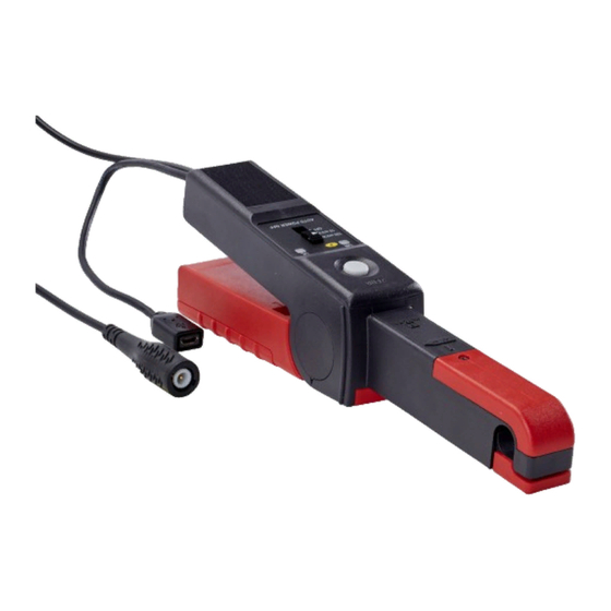
Page 5: E27 Clamp
1.5. E27 CLAMP Mobile jaw. Fixed jaw. Arrow indicating the direction of current flow. Guard Mobile arm. Reset button. 600 V CAT III Zéro ON and OL indicators. Male BNC connector. Three-position slide switch. 100 mV/A 10 mV/A AUTO POWER OFF Type B micro-USB con- nector. -
Page 6: Use
2. USE 2.1. GETTING STARTED Switch the clamp on by pushing the slide switch to the 10mV/A or the 100mV/A setting. The 10mV/A setting corresponds to the 100A range. The 100mV/A setting corresponds to the 10A range. The ON indicator lights green. If it blinks, there remain less than 4 hours of use. If it fails to light, you must replace the battery (see §... -
Page 7: Auto Off
If the OL indicator lights, it means that the current is too strong to be measured. If you are in the 100mV/A range, switch to the 10mV/A range. „ Apply the conversion factor corresponding to the setting of the switch. 100 mV/A 10 mV/A 500 mV... -
Page 8: Specifications
3. SPECIFICATIONS 3.1. REFERENCE CONDITIONS Quantity of influence Reference values Temperature 23 ± 5 °C Relative humidity 20 to 75%RH Position of the conductor centred Frequency of the measured signal DC to 65 Hz sine wave by battery: 6.5 to 9 V Powered external supply: 5 V ±... - Page 9 Typical amplitude error curve for a 60Hz AC current, 10mV/A range Error (%) 18,00 16,00 14,00 12,00 10,00 8,00 6,00 4,00 2,00 0,00 -2,00 -4,00 -6,00 -8,00 -10,00 -12,00 -14,00 -16,00 -18,00 Current (Aac) 3.2.2. NOISE Typical noise level at output 10mV/A range ±...
- Page 10 Typical amplitude error curve at 1A versus frequency, 100mV/A range Error (%) -1dB -2dB -3dB -4dB -5dB -6dB Frequency (Hz) 1000 10000 100000 1000000 Typical amplitude error curve as a function of frequency, I = 1A, 10mV/A range Phase shift (°) 0,00 -20,00 -40,00...
- Page 11 3.2.5. FREQUENCY CHARACTERISTICS Range 10mV/A 100mV/A Pass band to 3 dB down DC to 100 kHz Rise time (10 to 90%) and fall time (90 to 10%) 3 µs Response time to 10% 1.8 µs Insertion impedance at 10 kHz 2 mΩ...
-
Page 12: Operating Limits
3.3. OPERATING LIMITS „ Conductor temperature: ≤90°C, 110°C peak „ Temperature of the jaws: ≤ 80°C „ Curve of derating versus frequency Peak current (A) Frequency (Hz) 1 000 10 000 f (Hz) 3.4. VARIATIONS IN THE RANGE OF USE Error in % of reading Quantity of influence Range of influence... -
Page 13: Environmental Conditions
3.6. ENVIRONMENTAL CONDITIONS The device must be used in the following conditions: 1 = Range of reference. 2 = Operating range. 3 = Storage range. °C -50 -40 -30 -20 -10 0 10 20 30 40 50 60 70 80 90 Indoor use. -
Page 14: Conformity To International Standards
Protection by the housing „ IP 20 per IEC 60529 „ Resistance of the jaws per IEC 61010-2-032 3.8. CONFORMITY TO INTERNATIONAL STANDARDS The instrument is compliant with IEC 61010-2-032, 600 V in category III. Double or reinforced insulation Type of current sensor per IEC 61010-2-032: type A 3.9. -
Page 15: Maintenance
4. MAINTENANCE Except for the battery, the instrument contains no parts that can be replaced by personnel who have not been specially trained and accredited. Any unauthorized repair or replacement of a part by an “equivalent” may gravely impair safety. 4.1. - Page 16 5. Clamp a conductor carrying a current of: „ 10 Aac 60 Hz for the 10mV/A range „ 1 Aac 60 Hz for the 100mV/A range 6. Then press the DC Zero button. The first press substantially lowers the polarization adjustment of Hall effect sensors. Subsequent presses increase this adjustment by one step.
-
Page 17: Warranty
5. WARRANTY Except as otherwise stated, our warranty is valid for 24 months starting from the date on which the equipment was sold. Extract from our General Conditions of Sale provided on request. The warranty does not apply in the following cases: „... - Page 18 FRANCE INTERNATIONAL Chauvin Arnoux Chauvin Arnoux 12-16 rue Sarah Bernhardt Tél : +33 1 44 85 44 38 92600 Asnières-sur-Seine Fax : +33 1 46 27 95 69 Tél : +33 1 44 85 44 85 Our international contacts Fax : +33 1 46 27 73 89 info@chauvin-arnoux.com...
Need help?
Do you have a question about the E27 and is the answer not in the manual?
Questions and answers