Advertisement
Quick Links
Advertisement

Related Manuals for JK CFS-20

Summary of Contents for JK CFS-20
- Page 1 CFS-20 Combination Foldable Studreel & Floor Reel Instruction Manual...
- Page 2 Table of Contents Parts List……………………………………………………………………………………… 3 Assembly…………………………………………………………….…………… 5 Making Adjustments………………………………………………………………………….. 12...
- Page 3 Parts List...
- Page 4 Part Number Part Name Quantity Spindle Rod FSR-100 Hex Set–Screw Bushing FSR-101-A Wire Hub Arm FSR-102 Spring FSR-103 Wire Tray Arm Stop Washer FSR-104 Wire Tray Arm FSR-102 Star Hub FSR-106-B Small Washer FSR-108 Arms Assembly Nut & Screw FSR-109 Swivel Mount Assembly Weldment FSR-110 Stud Mount Assembly Weldment...
- Page 5 Assembly Assembly of Arms Assembly To assemble the wire hub and attach the wire tray arms (FSR-102), the wire hub arms (FSR-102) have to be attached to the star hub (FSR-106-B) using an arms assembly nut & screw (FSR-109) as shown in figure 1. Each wire hub arm should also be attached to one of the hub mount holes on the corresponding wire tray arm once again using an arms assembly nut &...
- Page 6 To finish assembling the arms assembly, the rest of the assembly has to slide onto the spindle rod (FSR-100). First, the set-screws in the hex set-screw bushings (FSR-101-A) have to be loosened so that they can slide onto the spindle rod. Next the swivel mount assembly weldment should be slid onto the bottom of the spindle rod.
- Page 7 Underneath the swivel mount assembly weldment, the wire guide (FSR-116) should be slid onto the spindle rod, seen in figure 3. To finish assembly, the set-screws in the wire guide and hex set-screw bushings should be tightened to raise the wire tray arms to the preferred angle. When this is achieved, the top het set-screw bushing should be snug with the top star hub, and the bottom bushing, stop washer, spring and small washer should securely rest on the bottom star hub.
- Page 8 assembly can then be detached from the floor bracket. When it is removed, make sure to screw the 5/16” bolt, washers & nut back onto the stud mount assembly weldment because it will be used later. Figure 4 The 5/16” bolt, washers & nut need to be unscrewed and removed first in order to dismount the stud mount assembly weldment from the floor bracket.
- Page 9 Figure 5 The 5/16” Bolt is used to attach the stud mount assembly weldment and the swivel mount assembly weldment together Dismounting the Arms assembly from the Out-of-Box Position Once again, the stud mount assembly weldment will come attached to the floor bracket. In order to use the floor bracket or the stud mount, they need to be separated.
- Page 10 Figure 6 The arms assembly comes screwed to the floor bracket. This must be dismounted. Mounting the Arms Assembly to the Floor Bracket The arms assembly has to be attached to the floor bracket in order to use it as a floor reel. First screw a 5/8”...
- Page 11 To maximize the mobility of the wire guide it is important to align the swivel mount assembly weldment properly. There is a bump on the floor bracket that was welded there to help you align the swivel mount. When the 5/8” jam nuts are tightened, make sure that the swivel mount assembly weldment aligns with the bump on the floor bracket as shown in figure 8.
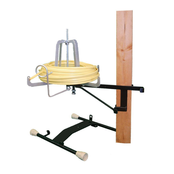
- Page 12 Figure 9 Mounting the assembly is easy. In this case the stud mount is being used for a 2x6 stud, but the two closest can be used for a 2x4. The FSR-C Combination Foldable Studreel & Floor Reel is now fully assembled. The next section will help you if you want to make some adjustments.
- Page 13 Figure 10 Screw bushing is slid up the spindle rod to raise the wire tray arms, or slid down to lower the arms. Adjusting Wire Tray Hub Diameter Sometimes it is necessary to adjust the diameter of the wire tray hub diameter to accommodate a different sized spool or wire.
- Page 14 Figure 11 Wire hub arms can be reattached at an alternate mounting hole in the wire tray arms to accommodate different spool. Note: only the two holes in the wire tray arms shown in figure 12 are meant to be used to mount to the wire hub arms.
Need help?
Do you have a question about the CFS-20 and is the answer not in the manual?
Questions and answers