Table of Contents
Advertisement
Quick Links
Advertisement
Chapters
Table of Contents

Related Manuals for Pegasolift W12


Summary of Contents for Pegasolift W12
- Page 1 W12 - W10 INOX W12 - MANUALE D’USO E MANUTENZIONE...
- Page 2 INFORMAZIONI ED AVVERTENZE GENERALI Il presente manuale d’uso e manutenzione permette di: raccogliere e rendere disponibili agli utenti finali i requisiti generali, le istruzioni particolari, i dati tecnici e tutte le informazione necessarie per eseguire una corretta ed accurata manutenzione dei carrelli elevatori prodotti dalla Pegaso s.r.l. di San Bonifacio (VR);...
-
Page 3: Table Of Contents
INDICE Schema indicazione misure ..............pag. 4 Tabella specifiche tecniche serie W12 ..........pag. 5 Grafici delle portate residue alle varie altezze ........pag. 6 Descrizione generale del carrello ............pag. 7 Identificazione del carrello e indicazioni particolari ....... pag. 8 Condizioni normali di impiego ............... -
Page 4: Schema Indicazione Misure
SCHEMA INDICAZIONE MISURE 1 - FRENATA 2 - MARCIA 1140 1265 1781 R1441... -
Page 5: Tabella Specifiche Tecniche Serie W12
TABELLA SPECIFICHE TECNICHE SERIE W12 SPECIFICHE TECNICHE VDI 2198 1.2 Modello W12SLG 1.3 Alimentazione Elettrica Elettrica 1.4 Posizione operatore a terra a terra 1.5 Portata 1200 1200 1.6 Baricentro del carico 1.9 Interasse ruote (mm) 1265 1265 Peso proprio - montanti simplex... -
Page 6: Grafici Delle Portate Residue Alle Varie Altezze
GRAFICI DELLE PORTATE RESIDUE ALLE VARIE ALTEZZE DURANTE L’UTILIZZO DEL CARRELLO RISPETTARE RIGOROSAMENTE IL PESO MASSIMO Q DEL CARICO DA SOLLEVARE PER LA RISPETTIVA ALTEZZA H DI SOLLEVAMENTO INDICATO NEL GRAFICO. PORRE PARTICOLARE ATTENZIONE ALLA BATTERIA CON CUI VIENE EQUIPAGGIATO IL CARRELLO E RIFERIRSI AL RELATIVO GRAFICO. -
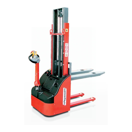
Page 7: Descrizione Generale Del Carrello
DESCRIZIONE GENERALE DEL CARRELLO Montante mobile Testata Montante fisso comandi Timone Portaoggetti completo Portabibite di portello di chiusura Fascione posteriore Cilindro oleodinamico Testata comandi Timone Rulli anteriori Cassoncino Forche... -
Page 8: Identificazione Del Carrello E Indicazioni Particolari
IDENTIFICAZIONE DEL CARRELLO E INDICAZIONI PARTICOLARI MODELLO MODEL NUMERO DI SERIE SERIAL NUMBER PORTATA NOMINALE RATED CAPACITY ALTEZZA DI SOLLEVAMENTO LIFTING HEIGHT MASSA SENZA BATTERIA WEIGHT WITHOUT BATTERY TENSIONE BATTERIA BATTERY VOLTAGE ATTENZIONE MASSA MIN BATTERIA MIN BATTERY WEIGHT WARNING MASSA MAX BATTERIA MAX BATTERY WEIGHT Pegaso srl, Via del Lavoro, 14 - Z.A. -
Page 9: Condizioni Normali Di Impiego
(1) che riassume i principali dati tecnici. Il modello viene identificato mediante una sigla alfanumerica composta da: ! il prefisso W12 seguito da un numero che indica la portata espressa in kN (quintali); ! una barra utilizzata come separatore;... -
Page 10: Norme Generali Di Sicurezza
NORME DI SICUREZZA L’OPERATORE HA L’AUTORITÀ DI: Impedire al personale non autorizzato l’uso del carrello di cui è responsabile; con “non autorizzato” si intende il personale che non ha la competenza necessaria all’impiego del carrello e che non ha la preventiva approvazione del supervisore. Impedire a chiunque di portarsi o sostare al di sotto delle forche sollevate, cariche o scariche. -
Page 11: Manovre Brusche Di Partenza, Frenata E Sterzata
NORME DI SICUREZZA Qualora le condizioni di lavoro si scostino dalle specifiche di collaudo (come nel caso di impilamento su piano inclinato) prendere le seguenti misure precauzionali: 1) se le condizioni straordinarie sono di natura permanente, prendere adeguati accordi con il supervisore e con le persone di pertinenza; 2) se le condizioni straordinarie sono di natura provvisoria, impiegare un carrello con portata maggiore o diminuire il carico. -
Page 12: Segnalazione Anomalie
NORME DI SICUREZZA Avere la massima cura quando si accatasta il materiale: se non è possibile ottenere una perfetta stabilità del carico, è opportuno legarlo e marciare adagio, ponendo la massima attenzione. Il sovraccarico compromette la stabilità e l’efficienza del mezzo: come visualizzato dalla figura A di pag. -
Page 13: Movimentazione Del Carrello
MOVIMENTAZIONE DEL CARRELLO Prima di procedere alle operazioni di sollevamento del carrello, accertarsi che il carrello sia disattivato rimuovendo la chiave; utilizzare esclusivamente il punto di ancoraggio indicato (altre posizioni potrebbero danneggiare la macchina). Impiegare solo cinghie in tessuto testate per pesi di almeno 1.000 kg: l’uso di catene o di ganci in metallo può... - Page 14 STRUMENTAZIONE 1) Interruttore staccabatteria: permette di sconnettere tutti gli apparati di bordo dalla batteria. 2) Carica batteria interno: visualizza, attraverso dei LED illuminati, il livello di carica della batteria e lo stato del processo di carica batteria. NOTA: dopo 2,5 minuti di inattività i LED si spengono automaticamente; per riattivarli è...
-
Page 15: Messa In Funzione Ed Uso Del Carrello
MESSA IN FUNZIONE ED USO DEL CARRELLO CONTROLLI PRELIMINARI: Il carrello pronto all’uso deve essere nelle seguenti condizioni: 1) Presa caricabatteria: disinserita. 2) Interruttore staccabatteria: inserito. 3) Barra del timone: in posizione verticale. 4) Gruppo elevatore: completamente abbassato. OPERAZIONE DI MARCIA AVANTI E MARCIA INDIETRO 1) Inserire il contatto di avviamento. -
Page 16: Ricarica Della Batteria
RICARICA DELLA BATTERIA PANNELLO FRONTALE RADRIZZATORE INTERNO Fuse: F8A universal input Do not remove the cover Danger of electric shocks Rete elettrica Quando sia accende il LED ROSSO (2) bisogna ricaricare la batteria come segue: A) Disinserire il contatto di avviamento (rif. Pag. 14 “Strumentazione” n° 1). B) Collegare il preposto cavo (1) al raddrizzatore interno (5) e quindi alla rete elettrica tramite una presa di corrente tipo “SCHUKO”... -
Page 17: Manutenzione Della Batteria
MANUTENZIONE DELLA BATTERIA PERICOLO! Durante la manutenzione delle batterie è obbligatorio indossare guanti, occhiali e mascherine protettivi. È vietato avvicinare fiamme libere, sigarette o altre sorgenti di scintille alle batterie. È vietato appoggiare utensili o parti metalliche sopra la batteria e/o scollegare i morsetti da una batteria sotto carica. -
Page 18: Controllo E Rabbocco Dei Livelli Dell'elettrolito
MANUTENZIONE DELLA BATTERIA MANUTENZIONE DELLA BATTERIA Se accidentalmente venisse ingerito dell’acido bere abbondante acqua, latte, chiaro d’uovo e comunque antiacidi quali magnesia e bicarbonato; consultare Se accidentalmente venisse ingerito dell’acido bere abbondante acqua, latte, chiaro immediatamente un medico ed un centro antiveleni. d’uovo e comunque antiacidi quali magnesia e bicarbonato;... -
Page 19: Recupero Giochi Montanti
RECUPERO GIOCHI MONTANTI Montante mobile Forche Cassoncino Controllare periodicamente i giochi tra i montanti e le forche; se sono eccessivi, occorre regolare i pattini dei gruppi di guida a sfere agendo come segue: 1 - muniti di una chiave esagonale n° 5, svitare il grano di sicurezza (2); 2 - avvitare il grano di registrazione (3) affinché... -
Page 20: Manutenzione Della Centralina Oleodinamica
MANUTENZIONE CENTRALINA OLEODINAMICA Periodicamente è necessario controllare il livello dell’olio della centralina oleodinamica che presiede alle operazioni di sollevamento del gruppo elevatore; per eseguire questa operazione seguire le seguenti indicazioni: 1) Abbassare il gruppo elevatore alla minima altezza possibile. 2) Disinserire il contatto di avviamento (rif. Pag. 14 “Strumentazione” n° 1). 3) Aprire il carter vano componenti. -
Page 21: Sostituzione Dell'anello Ruota
MANUTENZIONE DELLA MOTORUOTA SOSTITUZIONE DELL’ ANELLO RUOTA: Almeno una volta ogni anno è necessario controllare lo stato di usura dell’anello in poliuretano della motoruota; per sostituirlo occorre: 1) Disinserire il contatto di avviamento (rif. Pag. 14 “Strumentazione” n° 1). 2) Porre il carrello su dei cavalletti in sicurezza statica. 3) Agendo da sotto il carrello, rimuovere le 8 viti a testa cilindrica con esagono incassato indicate con (1). -
Page 22: Sostituzione Della Ruota D'appoggio Posteriore
MANUTENZIONE DELLA MOTORUOTA 6) Riavvitare le viti dei cavetti delle spazzole in modo da realizzare un buon contatto elettrico. 7) Chiudere la protezione (1). NOTA: durante queste operazioni fare molta attenzione a non lasciare cadere viti, rondelle o altro materiale all'interno del motore. ALTRI CONTROLLI PERIODICI : Ogni 500 ore verificare che non siano presenti deterioramenti o bruciature sulle molle premispazzola e sul collettore del rotore. -
Page 23: Esploso Elettroruota
ESPLOSO ELETTRORUOTA IT23... - Page 24 ESPLOSO ELETTRORUOTA POS. CODICE DESCRIZIONE Q.U. Vite..............01 Ruota .
-
Page 25: Schema Impianto Oleodinamico
SCHEMA IMPIANTO OLEODINAMICO SCHEMA IMPIANTO OLEODINAMICO Valvola paracadute Valvola paracadute VBA06 tarata a VBA06 tarata a 15 l/min a 160 bar 15 l/min a 160 bar C.C. C.C. Emergenza Emergenza TANK TANK IT25... -
Page 26: Schema Impianto Elettrico
SCHEMA ELETTRICO GIALLO BIANCO+VERDE BLU+NERO GRIGIO 11 ROSSO FUSE N.C. RIDUZIONE AUTOMATICA DI VELOCITA' 08 BIANCO+AZZURRO 05 ROSSO+NERO - AZZURRO + VIOLA ROSSO ROSSO NERO NERO IT26... - Page 27 W10 INOX W12 - W10 INOX MANUALE D’USO W12 - MAINTENANCE E MANUTENZIONE USER MANUAL...
- Page 28 GENERAL INFORMATION AND NOTIONS The present user manual allows: to collect and to put at the disposal of final users the general requirements, the precise instructions, the technical data and all the necessary information to be followed in order to achieve a correct and accurate maintenance of the stackers series PH manufactured by Pegaso s.r.l.
- Page 29 INDEX INDEX Dimensions scheme ..................pag. 4 Dimensions scheme ..................pag. 4 Technical specification table WAVE12 series ..........pag. 5 Technical specification table WAVE12 series ..........pag. 5 Diagrams of loads at different heights ............pag. 6 Diagrams of loads at different heights ............pag. 6 Stacker identification and detailed information ..........
- Page 30 TECHNICAL SPECIFICATION TABLE WAVE 12 SERIES 1 - BRAKING 2 - RUNNING 1140 1265 1781 R1441...
- Page 31 TECHNICAL SPECIFICATION TABLE WAVE 12 SERIES TECHNICAL SPECIFICATION TABLE WAVE 12 SERIES TECHNICAL SPECIFICATION VDI 2198 TECHNICAL SPECIFICATION VDI 2198 M odel W 12 W 12S LG M odel W 12 W 12S LG D rive E lectric D rive Electric Operator type Pedestrian...
- Page 32 DIAGRAMS OF LOAD AT DIFFERENT HEIGHTS D U R I N G T H E U T I L I Z AT I O N O F T H E STACKER, IT SHOULD STRICTLY OBSERVE THE MAX WEIGHT Q OF THE LOAD TO BE LIFTED FOR THE RESPECTIVE HEIGHT H OF RAISE INDICATED ON THE DIAGRAM.
- Page 33 STACKER IDENTIFICATION AND DETAILED INFORMATION STACKER IDENTIFICATION AND DETAILED INFORMATION ATTENZIONE ATTENZIONE WARNING WARNING...
- Page 34 STACKER IDENTIFICATION AND DETAILED INFORMATION STACKER IDENTIFICATION AND DETAILED INFORMATION On each stacker there is, on the left side in the movement direction, an identification tag On each stacker there is, on the left side in the movement direction, an identification tag (1) containing the main technical data.
- Page 35 GENERAL DESCRIPTION OF THE PALLET STACKER GENERAL DESCRIPTION OF THE PALLET STACKER Mobile mast Mobile mast Fixed mast Fixed mast Lifting group Lifting group Tiller head Tiller head forks forks Tiller Tiller Electronic Electronic components cover components cover Rear protection Rear protection Oleodynamic cylinder Oleodynamic cylinder...
- Page 36 GENERAL NORMS OF SAFETY GENERAL NORMS OF SAFETY THE OPERATOR HAS THE AUTHORITY TO..: THE OPERATOR HAS THE AUTHORITY TO..: To prevent the use about a non-authorized personal of the stacker for which he is To prevent the use about a non-authorized personal of the stacker for which he is responsible;...
- Page 37 GENERAL NORMS OF SAFETY GENERAL NORMS OF SAFETY When the work conditions differ from the testing ones (as is the case of piling on When the work conditions differ from the testing ones (as is the case of piling on inclined surface) there should be undertaken the following measures: inclined surface) there should be undertaken the following measures: 1) if the extraordinary conditions have a permanent character, to undertake...
- Page 38 GENERAL NORMS OF SAFETY GENERAL NORMS OF SAFETY Take care when the material is concentrating in one part: if there is not possible to Take care when the material is concentrating in one part: if there is not possible to obtain a perfect stability of the load, it is adequate to tie up it and to move slowly, obtain a perfect stability of the load, it is adequate to tie up it and to move slowly, paying maximum attention.
- Page 39 STACKER MOVEMENT STACKER MOVEMENT Before to proceed to the operations of lifting the stacker, check if the stacker is Before to proceed to the operations of lifting the stacker, check if the stacker is deactivated, taking off the key, use exclusively the anchoring point indicated (other deactivated, taking off the key, use exclusively the anchoring point indicated (other positions could damage the machine).
- Page 40 INSTRUMENTS AND TILLER HEAD INSTRUMENTS AND TILLER HEAD INSTRUMENTS: INSTRUMENTS: 1) Start key: allows to disconnect all the electronic part of the desk of the battery 1) Start key: allows to disconnect all the electronic part of the desk of the battery 2) Internal battery charger: displays, with illuminated LED elements, the charge level of 2) Internal battery charger: displays, with illuminated LED elements, the charge level of the battery and the load situation of the battery charge process.
- Page 41 PUTTING IN FUNCTION AND STACKER UTILISATION PUTTING IN FUNCTION AND STACKER UTILISATION PRELIMINARY CONTROLS: PRELIMINARY CONTROLS: The stacker ready to use must be in the following conditions: The stacker ready to use must be in the following conditions: 1) Battery loading tap: disconnected. 1) Battery loading tap: disconnected.
- Page 42 BATTERY CHARGE BATTERY CHARGE INTERNAL BATTERY CHARGER FRONTAL PANEL INTERNAL BATTERY CHARGER FRONTAL PANEL Fuse: F8A universal input Fuse: F8A universal input Do not remove the cover Do not remove the cover Danger of electric shocks Danger of electric shocks Rete Rete elettrica...
- Page 43 BATTERY MAINTENANCE BATTERY MAINTENANCE DANGER! DANGER! During the maintenance of the battery it is obligatory During the maintenance of the battery it is obligatory to wear safety gloves, glasses and masks. to wear safety gloves, glasses and masks. It is prohibited to bring near to the battery open fire, It is prohibited to bring near to the battery open fire, cigarettes or other sources of sparks.
- Page 44 BATTERY MAINTENANCE BATTERY MAINTENANCE CONTROL AND FILLING UP OF THE ELECTROLYTE LEVEL: CONTROL AND FILLING UP OF THE ELECTROLYTE LEVEL: Periodically check the level of the battery electrolyte; if it is necessary, execute the filling Periodically check the level of the battery electrolyte; if it is necessary, execute the filling up only with demineralised water according to the norms CEI21-5 fascicle 255 taking up only with demineralised water according to the norms CEI21-5 fascicle 255 taking into account that:...
- Page 45 MAINTENANCE OF THE OLEODYNAMIC POWER UNIT MAINTENANCE OF THE OLEODYNAMIC POWER UNIT Periodically it is necessary to control the level of ole-dynamic power unit which directs Periodically it is necessary to control the level of ole-dynamic power unit which directs the lifting operations of the lifting group, in order execute the following instructions: the lifting operations of the lifting group, in order execute the following instructions: 1) lower the lifting group at the minimum possible height...
- Page 46 RECOVER THE MAST CLEARENCE RECOVER THE MAST CLEARENCE Montante mobile Montante mobile Forche Forche Cassoncino Cassoncino Periodically control the clearances between the mast and the forks; if they are excessive Periodically control the clearances between the mast and the forks; if they are excessive is necessary to regulate the sliding block of the guide group as follows: is necessary to regulate the sliding block of the guide group as follows: 1.
- Page 47 CASTOR WHEEL REPLACEMENT CASTOR WHEEL REPLACEMENT Also the castor wheel is subject to wear itself. Also the castor wheel is subject to wear itself. For replacement is necessary operate as follows: For replacement is necessary operate as follows: 1) disconnect the start key (reference page 13 1) disconnect the start key (reference page 13 “instruments”...
- Page 48 TRACTION WHEEL MAINTENANCE REPLACEMENT OF WHEEL RING At least once a year it is necessary to control the covering of the polyurethane ring of the motor wheel, if is necessary to replace it operate as follow : 1) disconnect the start key (reference page 14 “Instruments” no. 1) 2) put the truck on safety supports 3) From the under part of the stacker.
- Page 49 TRACTION WHEEL MAINTENANCE 6) screw again the screws of the brush elements (2) to realize a good electric contact. 7) close the strip covering the brushes. NOTE: during these operations pay much attention to not let screws, washers or another material to fall in the interior of the motor.
- Page 50 TRACTION WHEEL EXPLODED VIEW TRACTION WHEEL EXPLODED VIEW UK24...
- Page 51 TRACTION WHEEL EXPLODED VIEW TRACTION WHEEL EXPLODED VIEW POS. POS. CODE CODE DESCRIPTION DESCRIPTION U.Q. U.Q. Fixing wheel ring screw ..........08 Fixing wheel ring screw .
- Page 52 OLEO-DYNAMIC PLAN OLEO-DYNAMIC PLAN Safety block valve Safety block valve V B A 0 6 s e t t o V B A 0 6 s e t t o 15 l/min at 160 bar 15 l/min at 160 bar C.C.
- Page 53 WIRING PLAN WIRING PLAN GRIGIO GRIGIO UK27...
- Page 54 W12 - GUIA USO Y LA W12 - GUIA USO Y LA MANTENIMENTO MANTENIMENTO...
- Page 55 INFORMACIONES Y ADVERTENCIAS GENERALES Este manual para el uso y el mantenimiento permite: ! recoger y poner a disposición de los usuarios finales los requisitos generales, las instrucciones detalladas, los datos técnicos y todas las informaciones necesarias para ejecutar un correcto y esmerado mantenimiento de las carretillas elevadoras de la serie WAVE producidas por Pegaso s.r.l.
- Page 56 ÍNDICE Esquema de indicación de medidas ....... . . pag. 04 Tabla de notas técnicas de las carretillas serie WAVE .
-
Page 57: Esquema De Indicación De Medidas
ESQUEMA DE INDICACIÓN DE MEDIDAS 1 - BRAKING 2 - RUNNING 1140 1265 1781 R1441... -
Page 58: Tabla De Notas Técnicas De Las Carretillas Serie Wave
TABLA DE NOTAS TÉCNICAS DE LAS CARRETILLAS SERIE WAVE TECHNICAL SPECIFICATION VDI 2198 M odel W 12 W 12S LG D rive Electric Operator type Pedestrian R ated capacity/rated load 1200 Load centre distance W heel base 1265 N et weight incl. battery-simplex mast N et weight incl. -
Page 59: Gráficos De Las Capacidades Restantes A Diferentes Alturas
GRÁFICOS DE LAS CAPACIDADES RESTANTES A DIFERENTES ALTURAS D U R A N T E LA U T I L I Z AC I Ó N D E LA C A R R E T I L L A H AY Q U E R E S P E TA R RIGOROSAMENTE EL PESO MÁXIMO Q DE LA CARGA PARA ELEVAR, POR EL C O R R E S P O N D I E N T E A LT O H D E... - Page 60 IDENTIFICACIÓN DE LA CARRETILLA E INDICACIONES DETALLADAS ATTENZIONE WARNING...
-
Page 61: Condiciones Normales De Empleo
IDENTIFICACIÓN DE LA CARRETILLA E INDICACIONES DETALLADAS En cada carretilla elevadora está, en el lado derecho en sentido de marcha, una etiqueta de identificación (1) la cual resume los datos técnicos principales. El modelo es identificado por medio de una código alfanumérico que se compone de: ! El prefijo WAVE seguido de un número que indica la capacidad en KN (quintales);... -
Page 62: Descripción General De La Carretilla
DESCRIPCIÓN GENERAL DE LA CARRETILLA Montante móvil Montante fijo Conjunto Cuadro elevador de mando Horquillas Timón Carter hueco componentes Tapa trasera Cilindro oleodinámico Cuadro de mando Timón Rodillos delanteros Compartimento batería Horquillas... -
Page 63: El Operador Tiene La Autoridad De
NORMAS DE SEGURIDAD EL OPERADOR TIENE LA AUTORIDAD DE: Impedir al personal no autorizado la utilización de la carrettilla de la cual es responsable ; las palabras “no autorizado” quieren decir el personal que no tiene la competencia necesaria para utilizar la carretilla y que no tiene una previa aprobación del supervisor. -
Page 64: Transporte De La Carga
NORMAS DE SEGURIDAD 3) el vehículo para cargar este bien fijado mediante dispositivos como cuñas en las ruedas o otros por el estilo. ! En caso de que las condiciones de trabajo se aparten de las especificaciones generales (como en el caso de apilamiento sobre plano inclinado), tomar las siguiente medidas preventivas: 1) si las condiciones extraordinarias son permanentes, tomar acuerdos adecuados con el supervisor y con las personas pertinentes;... -
Page 65: Señalización De Anomalías
NORMAS DE SEGURIDAD ! Poner la máxima cura cuando se apila el material: si no es posible obtener una perfecta estabilidad de la carga, es mejoratarlo atarlo y marchar despacio, ponendo la máxima atención. ! La sobrecarga compromete la estabilidad y el rendimiento de la carretilla: como se puede visualizar en la figura A de página 11, la carga tiene que estar situada lo más cerca posible de la cabeza del conjunto elevador, de modo que se pueda repartir más uniformemente el peso sobre las cuatro ruedas. -
Page 66: Transporte De La Carretilla
TRANSPORTE DE LA CARRETILLA Antes de proceder a las operaciones de elevación de la carretilla, asegurarse de que la carretilla esté desactivada, removiendo la llave del cuadro de mando; utilizar exclusivamente el punto de anclaje señalado (otras posiciones podrían arruinar la máquina). -
Page 67: Instrumentos Y Cuadro De Mando
INSTRUMENTOS Y CUADRO DE MANDO INSTRUMENTOS 1. Interruptor de desconexión de batería: permite desconectar las instalaciones eléctricas de bordo de la batería. 2. Cargador interior de batería: visualiza, por medio de LED luminosos, el estado del proceso de carga de la batería. CUADRO DE MANDO 1. -
Page 68: Operaciones De Marcha Adelante Y Marcha Atrás
PUESTA EN MARCHA Y EMPLEO DE LA CARRETILLA INSPECCIONES PRELIMINARES La carretilla lista para la utilización tiene que presentar las siguientes condiciones: 1. Enchufe cargador baterías: desconectado. 2. Interruptor de desconexión de batería: conectado. 3. Barra del timón: en posición vertical. 4. -
Page 69: Recarga De La Batería
RECARGA DE LA BATERÍA PANEL FRONTAL ENDEREZADOR INTERIOR Fuse: F8A universal input Do not remove the cover Danger of electric shocks eléctrica Cuando el indicador de carga de la batería (véase página 14 "Cuadro de mando" n. 5) tenga un único LED encendido, hay que recargar la batería como sigue: A. -
Page 70: Mantenimiento De La Batería
MANTENIMIENTO DE LA BATERÍA ¡PELIGRO! Durante el mantenimiento de las baterías es obligatorio llevar guantes, gafas y máscaras protectoras. Esta prohibido acercar llamas libres, cigarillos u otras fuentes de chispas a las baterías. Esta prohibido apoyar utensilios o partes metálicas sobre la batería y/o desconectar los bornes de una batería bajo carga. -
Page 71: Control Y Rellenado De Los Niveles Del Electrólito
MANTENIMIENTO DE LA BATERÍA CONTROL Y RELLENADO DE LOS NIVELES DEL ELECTRÓLITO: Verificar periodicamente el nivel del electrólito de la batería; cuando sea necesario, ejecutar el rellenado sólo con agua destilada de acuerdo con las normas CEI21-5, fascículo 255, teniendo presente que: 1) Es absolutamente prohibido ejecutar rellenados con ácido sulfúrico. -
Page 72: Mantenimiento De La Centralita Oleodinámica
MANTENIMIENTO DE LA CENTRALITA OLEODINÁMICA Periodicamente es necesario controlar el nivel del aceite de la centralita hidráulica que realiza las operaciones de elevación del conjunto elevador; para ejecutar esta operación, seguir las indicaciones siguientes: 1. Bajar el conjunto elevador hasta la mínima altura posible. 2. -
Page 73: Recuperación De Los Juegos De Los Montantes
RECUPERACIÓN DE LOS JUEGOS DE LOS MONTANTES Montante móvil Horquillas Compartimento batería Controlar periodicamente los juegos entre montantes y horquillas; si son exagerados, es necesario regular los patines de las guías de fricción de los rodamientos actuando como sigue: 1. con una llave hexagonal n° 5, desatornillar el tornillo prisioNIGRO de seguridad (2); 2. -
Page 74: Sustitución De La Rueda De Apoyo Trasera
SUSTITUCIÓN DE LA RUEDA DE APOYO TRASERA También la rueda de apoyo trasera está sujeta a desgastes. Para ejecutar su sustitución hay que: 1. Desconectar el contacto de puesta en marcha (véase página 14 "Instrumentos", n° 1). 2. Poner la carretilla sobre caballetes en seguridad estática. -
Page 75: Sustitución Del Anillo De La Rueda
MANTENIMIENTO DEL GRUPO MOTOR-RUEDA SUSTITUCIÓN DEL ANILLO DE LA RUEDA: Al menos una vez al año es necesario controlar el estado de desgaste del bandaje de poliuretano de la motorueda; para sustituirlo hay que: 1. Desconectar el contacto de puesta en marcha (véase página 14 "Instrumentos", n° 1). 2. - Page 76 MANTENIMIENTO DEL GRUPO MOTOR-RUEDA NOTA: Durante estas operaciones poner mucha atención a no dejar caer tornillos, rondanas u otro material adentro del motor. OTROS CONTROLES PERIÓDICOS Cada 500 horas asegurarse de que no haya deterioros o quemaduras en los muelles que apretan las escobillas y en el colector del motor.
-
Page 77: Explotado De La Electrorueda
EXPLOTADO DE LA ELECTRO-RUEDA ES24... - Page 78 EXPLOTADO DE LA ELECTRO-RUEDA POS. CÓDIGO DESCRIPCIÓN Q.U. Tornillo ......................01 Rueda .......................01 Arandela ....................01 Protección....................01 Cojinete a bolas..................01 Engranaje ....................01 OR ......................01 Bandaje de adherencia................01 Fusión.......................01 Guarnición del émbolo................01 Cojinete a bolas..................01 Engranaje ....................01 Engranaje ....................01 Cojinete ....................01 Bandaje de adherencia................01 Guarnición de la plancha del freno ............01 Plancha del freno..................01 Disco de freno ..................01...
-
Page 79: Esquema De La Instalación Oleodinámica
ESQUEMA DE LA INSTALACIÓN OLEODINÁMICA Válvula paracaídas V B A 0 6 t a r a d a 15 l/min a 160 bar C.C. EMERGENCIA TANK ES26... - Page 80 ESQUEMA ELÉCTRICO GRIS ES27...
- Page 81 INDEX ES28...
- Page 82 W12 - MANUAL DE USO...
- Page 83 INFORMAÇÕES E ADVERTÊCIAS GERAIS O presente manual de uso e manutenção permite : Recolher e disponibilizar aos utilizadores finais os requisitos gerais, instruções especiais, dados técnicos e todas as informações necessárias para executar uma manutenção adequada e precisa das empilhadeiras produzidas pela Pegaso s.r.l. De San Bonifacio (VR);...
- Page 84 Schema indicazione misure ..............pag. 4 INDICE INDICE Tabella specifiche tecniche serie W12 ..........pag. 5 -Tabela específicações técnicas série W12 ............ pag. 33 Schema indicazione misure ..............pag. 4 Grafici delle portate residue alle varie altezze ........pag. 6 -Gráficos das capacidades residuais para várias alturas .......
- Page 85 ESQUEMA INDICAÇÃO MEDIDAS 1 - BRAKING 2 - RUNNING 1140 1265 1781 R1441...
- Page 86 TABELA ESPECIFICAÇÕES TÉCNICAS SÉRIE W12 TECHNICAL SPECIFICATION VDI 2198 M odel W 12 W 12S LG Electric D rive Operator type Pedestrian R ated capacity/rated load 1200 Load centre distance W heel base 1265 N et weight incl. battery-simplex mast N et weight incl.
- Page 87 GRÁFICOS DAS CAPACIDADES RESIDUAIS PARA VÁRIAS ALTURAS DURANTE O USO DA EMPILHADEIRA RESPEITTAR RIGOROSAMENTE O PESO MÁXIMO (Q) DA CARGA A SER ELEVADA P E LA R E S P E C T I VA A LT U R A ( H ) D E ELEVAÇÃO INDICADA NO GRÁFICO.
- Page 88 DESCRIÇÃO GERAL DA EMPILHADEIRA Torre móvel Alavanca Torre fixa comandos Timão Porta objetos completo Porta bebidas com tampa Carenagem posterior Cilindro hidráulico Alavanca de comando Timão Roda anterior Chassi Garfos...
- Page 89 IDENTIFICAÇÃO DA MÁQUINA E INDICAÇÕES PARTICULARES ATTENZIONE WARNING 2 × 12V 105Ah Pb/ACID BATERIAS CAPACIDADE RESIDUAL 2 × 12V 100Ah GEL BATERIAS Rated capacity: 1200 kg Q=1200 kg 950 kg 850 kg 700 kg 450 kg...
- Page 90 IDENTIFICAÇÃO DA MÁQUINA E INDICAÇÕES PARTICULARES Sobre cada máquina, do lado direito, no senso de marcha, encontra-se uma placa identificativa (1) a qual resume os principais dados técnicos. O modelo é identificado por um código alfanumérico composto por: ! Prefixo WAVE seguido de um número que indica a capacidade expressa em ! Uma barra utilizada como separador;...
- Page 91 NORMAS DE SEGURANÇA O OPERADOR TEM AUTORIDADE DE Impedir o uso da empilhadeira pela qual è responsável, por pessoal não autorizado.. “Não autorizado” significa pessoal que não tenha a competência necessária para uso da emplhadeira e que não tenha prévia aprovação do supervisor. Não permitir a qualquer pessoa que seja, parar ou permanecer debaixo da empilhadeira, de carga ou descarga.
- Page 92 NORMAS DE SEGURANÇA Se as condições de trabalho divergirem das especificações de teste (como no caso de empilhamento sobre um plano inclinado) tomar as seguintes precauções: 1) se as condições extraordinárias são permanentes, fazer acordos adequados com o supervisor e pessoas de relevância; 2) se as condições extraordinárias são provisórias, usar uma empilhadeira com uma capacidade superior ou diminuir a carga.
- Page 93 NORMAS DE SECURANÇA Ter o máximo de cuidado quando empilhar o material: Caso não seja posssível obter uma perfeita estabilidade da carga, è oportuno amarrá-lo e seguir lentamente, prestando a máxima atenção. A sobrecarga compromete a estabilidade e a eficiência do meio: como mostrado na Figura A na página.
- Page 94 MOVIMENTAÇÃO DA EMPILHADEIRA Antes de proceder com as operações de elevação das empilhadeiras, verificar se a máquina encontra-se desligada removendo a chave ; utilizar exclusivamente o ponto de ancoragem indicado (outras posições podem danificar a máquina). Usar somente correias em tecido testadas para pesos de almenos 1.000 kg: O uso de corentes ou ganchos de metal podem danificar a pintura .
- Page 95 INSTRUMENTAÇÕES 1) Interruptor desliga bateria: permite desconectar todos os equipamentos a bordo da bateria. 2) Carregador de bateria interno: visualiza, através de LED iluminados, o nível de carga da bateria e o estato do processo de carga da bateria. NOTA: Após 2,5 minutos de inatividade os LEDs se apagam automaticamente. Para riativa-los è...
- Page 96 OPERAÇÃO E USO DA EMPILHADEIRA CONTROLES PRELIMINARES: A máquina pronta ao uso deve estar nas seguintes condicões: 1) Tomada do carregador: desativado.. 2) Interruptor desconecta batteria: inserido. 3) Barra do timão em posição vertical. 4) Grupo de elevação: completamente abaixado. OPERAÇÕES DE MARCHAS 1) Inserir o contato de partida.
- Page 97 CARREGAR BATERIA PAINEL FRONTAL CARREGADOR INTERNO Fuse: F8A universal input Do not remove the cover Danger of electric shocks corrente elétrica Quando se acende o LED VERMELHO (2) precisa carregar a bateria como segue: A) Desligue o contato inicial (rif. Pag. 14 “Instrumentação” n° 1). B) Conecte o cabo de carga (1) o carregador interno (5) e depois a rede elétrica através de uma tomada tipo "Schuko"...
- Page 98 MANUTENÇÃO DA BATERIA PERIGO! Durante a manutenção da bateria é necessária a utilização de luvas, óculos e máscaras protetoras. É proibido aproximar chamas livres, cigarros ou outras fontes de faíscas às baterias. É proibido apoiar ferramentas ou partes metálicas sobre a bateria e/ou desligar os terminais da bateria em carga.
- Page 99 MANUTENÇÃO DA BATERIA Se ingerido acidentalmente ácido, beber em abundância água, leite, clara de ovo e antiácidos, como magnésio e bicarbonato, no entanto, consultar imediatamente um médico e um centro de controle de veneno. CONTROLE E PREENCHIMENTO DO NÍVEL DE ELETRÓLITO :: Verificar periodicamente o nível eletrólitos da bateria, se necessário, executar o preenchimento com água desmineralizada conforme as normasCEI21-5 P.
- Page 100 RECUPERAÇÃO DE FOLGAS TORRES Torre móvel Garfos Chassi Verificar periodicamente as folgas entre a torre e garfos, e se elas são excessivas, ocorre ajustar as guias laterais (1) da seguinte forma 1 - equipado com uma chave exagonal n º 5, desapertar o parafuso de segurança(2); Desapertar o parafuso de ajuste (3) até...
- Page 101 MANUTENÇÃO UNIDADE HIDRÁULICA Verifique periodicamente o nível do óleo da unidade hidráulica, que preside as operacões do grupo elevação. Para executar essas operações, seguir os seguintes passos: 1) Abaixar ogrupo elevação à altura mínima possível. 2) Desligar o contato inicial (rif. Pag. 14 “Instrumentação” n° 1). 3) Abrir o compartimento.
- Page 102 MANUTENÇÃO DA RODA MOTRIZ SUBSTITUIÇÃO DO ANEL DA RODA : Pelo menos uma vez por ano é necessário verificar o estado de desgaste do anel em poliuretano na roda motriz . Para substituí-lo: 1) Desligar o contato inicial (rif. Pag. 14 “Instrumentação” n° 1). 2) Colocar a máquina sobre cavaletes em segurança estática.
- Page 103 MANUTENÇÃO DA RODA MOTRIZ 6) Parafusar novamente os cabos das escovas de modo a realizar um bom contato elétrico 7) Fechar as proteções (1). NOTA: durante essas operações ter muito cuidado para não deixar cair parafusos, arruelas e outros materiais dentro do motor. OUTROS CONTROLES PERIODICOS : A Cada 500 horas verificar que não seja presente deterioração ou queimaduras nas molas de pressão das escovas e coletores do rotor.
- Page 104 TRACTION WMEEL EXPLODED VIEW PT23...
- Page 105 TRACTION WMEEL EXPLODED VIEW POS. CODIGO DESCRIÇÃO Q.U. Parafusos............01 Roda .
- Page 106 ESQUEMA SISTEMA HIDRÁULICO Válvula páraquedas VBA06 calibrada a 15 l/min a 160 bar C.C. Emergência TANK PT25...
- Page 107 ESQUEMA ELÉTRICO CINZA PT26...
- Page 108 W12 - GUIDE D’EMPLOI ET MAINTENANCE...
- Page 109 INFORMATIONS ET AVERTISSEMENTS GÉNÉRAUX Le présent guide d'emploi et maintenance Vous permis de: – Recueillir et rendre disponibles pour les utilisateurs finals les requises généraux, les instructions particulières, les données techniques et tous les informations nécessaires pour exécuter une correcte et soignée maintenance des gerbeurs élévateurs produits par Pegaso s.r.l.
- Page 110 ÍNDICE ÍNDICE ÍNDICE INDEX ÍNDICE ÍNDICE ÍNDICE Esquema de indicación de medidas ....... . . pag. 04 Esquema de indicación de medidas .
- Page 111 TABLEAU DETAILS TECHNIQUES 1 - BRAKING 2 - RUNNING 1140 1265 1781 R1441...
- Page 112 TABLEAU DETAILS TECHNIQUES SERIE WAVE12 SPECIFICATIONS GÉNÉRALE VDI 2198 1.2 Modèle W12SLG 1.3 Mode de propulsion électrique 1.4 Conduite accompagnant 1.5 Capacité nominale 1200 1200 1.6 Centre de gravité 1.9 Empattement 1265 1265 Poids propre avec batterie - Mât simple Poids propre avec batterie - Mât duplex n.d.
- Page 113 GRAPHIQUES DES PORTÉES RÉSIDUELLES AUX DIFFÉRENTES HAUTEURS PENDENT L'UTILISATION DU GERBEUR IL FAUT RESPECTER RIGOUREUSEMENT LE POIDS MAXIMAL Q DE LA CHARGE S O U L E V E R P O U R L A R E S P E C T I V E HAUTEUR H D'ÉLÉVATION INDIQUÉE DANS LE GRAPHIQUE.
- Page 114 IDENTIFICATION DU GERBEUR ET INDICATIONS PARTICULIÈRES ATTENZIONE WARNING...
- Page 115 IDENTIFICATION DU GERBEUR ET INDICATIONS PARTICULIÈRES Sur chaque gerbeur on a, au côté gauche en sens de marche, une plaque d'identification (1) qui résume les principales données techniques. Le modèle est identifié par un sigle alphanumérique composé par : * Le préfixe WAVE suivi par un numéro qui indique la capacité exprimée en kN (quintaux) * Une barre utilisée comme séparateur ;...
- Page 116 DESCRIPTION GENERALE DU GERBEUR Mât mobile Mât fixe Fourches Tête du timon Timon Carter postérieur Protection postérieur Vérin hydraulique Tête du timon Timon Galets antérieurs Châssis Fourches...
- Page 117 CONSIGNES DE SÉCURITÉ LE CONDUCTEUR A L'AUTORITÉ DE: * Empêcher au personnel pas autorisé l'usage du gerbeur dont il est responsable; avec l'expression " pas autorisé " on entend le personnel qui n'a pas la compétence nécessaire l'utilisation du gerbeur et qui n'a pas obtenu la préventive autorisation du superviseur. * Empêcher n'importe qui d'aller ou s'arrêter au-dessous des fourches soulevées, chargées ou vide.
- Page 118 CONSIGNES DE SÉCURITÉ * Dans le cas où les conditions de travail et ces d'essai seraient différentes (comme dans le cas d'empilage sur une pente) prendre les suivantes mesures de précaution: 1) si les conditions extraordinaires sont permanentes, prendre accords avec le superviseur et le personnel de compétence.
- Page 119 CONSIGNES DE SÉCURITÉ * Avoir soin quand on empile le matériel: s'il n'est pas possible obtenir une parfaite stabilité de la charge, il faut le lier et se déplacer lentement, en faisant une grande attention. * La surcharge compromise la stabilité et l'efficacité du gerbeur: comment on peut voir dans l'illustration la page 14, la charge doit être positionnée appuie la face avant des fourches de sorte que le poids soit réparti uniformément sur les quatre roues.
- Page 120 SOULÈVEMENT DU GERBEUR Avant de procéder avec les opérations de soulèvement du gerbeur, vérifier que le gerbeur sera débranché et la clé de contacte enlevée; utiliser exclusivement les points d'ancrage indiqués (autre positions pourraient endommager le gerbeur). Utiliser seulement bandes pour soulèvement en tissu avec une portée minimum de 1000 kg : l'usage de chaînes ou crochets en métal peut endommager la peinture.
- Page 121 INSTRUMENTATION ET TETE DU TIMON Instrumentation 1) Clé de coupure de courant batterie/gerbeur: elle permit de brancher ou débrancher toutes les appareilles de bord à la batterie. 2) Chargeur embarqué de la batterie : il visualise, par des diodes éclairées, le procédé de charge de la batterie.
- Page 122 MISE EN MARCHE ET EMPLOI DU GERBEUR CONTRÔLES PRÉLIMINAIRES Le gerbeur prêt l'usage doit être dans les suivantes conditions : 1) Connecteur de courant: débranchée. 2) Clé de contact: elle doit être débranchée et la clé enlevée. 3) Bouton de coupure du courant: branchée. 4) Timon: en position verticale.
- Page 123 CHARGE DE LA BATTERIE Tableau de contrôle chargeur embarqué Fuse: F8A universal input Do not remove the cover Danger of electric shocks Réseau électrique Quand l'indicateur de charge de la batterie (réf. à la page 14 Tête du timon part. 5) a le LED jaune éclairé...
- Page 124 MAINTENANCE DE LA BATTERIE DANGER ! Pendant la maintenance des batteries est obligatoire porter gants, lunettes et respirateur de protection. Il est interdit d'approcher flammes libres, cigarettes ou autres sources des étincelles aux batteries. Il est interdit de poser outillages ou pièces métalliques sur la batterie et/ou débrancher une batterie pendant sa charge.
- Page 125 MAINTENANCE DE LA BATTERIE CONTRÔLE ET REMPLISSAGE DES NIVEAUX DE L'ÉLECTROLYTE : Vérifier périodiquement le niveau de l'électrolyte de la batterie; si nécessaire, remplir seulement avec eau déminéralisée conformément aux normes CEI21-5 fascicule 255, en considérant que : 1) il est absolument interdit remplier avec de l'acide sulfurique. 2) le remplissage doit être fait seulement après une charge complète avec son égalisation: un remplissage batterie déchargée est exposé, au moment de la charge,...
- Page 126 MAINTENANCE DE LA POMPE HYDRAULIQUE Périodiquement c'est nécessaire contrôler le niveau de l'huile de la pompe hydraulique pour les fonctions d'élévation et de descente des fourches ; faire cette opération comme en suite : 1) Baisser les fourches jusqu'à la hauteur minime possible. 2) Débrancher la clé...
- Page 127 RÉGLAGE DES JEUX DES MÂTS ET FOURCHES Contrôler périodiquement les jeux entre les mâts et les fourches; s'ils sont excessifs, il faut régler les patins des roulements comme indiqué en suite: 1- dévisser la vis de sécurité (2); 2- visser la vis de réglage (3) pour faire sortir le patin (1) et récupérer le jeu en excès; 3- visser avec soin la vis de sécurité;...
- Page 128 REMPLACEMENT DE LA ROUE STABILISATRICE POSTERIEURE Même la roue stabilisatrice postérieure est sujette à l'usure. Pour la remplacer il faut: 1) Presser le bouton de coupure du courant pour débrancher la batterie (réf. à la page 17 Instrumentation part. 1) 2) Mettre le gerbeur sur des chevalets en sécurité...
- Page 129 RÉGLAGE DES JEUX DES MÂTS ET FOURCHES Contrôler périodiquement les jeux entre les mâts et les fourches; s'ils sont excessifs, il faut régler les patins des roulements comme indiqué en suite: 1- dévisser la vis de sécurité (2); 2- visser la vis de réglage (3) pour faire sortir le patin (1) et récupérer le jeu en excès; 3- visser avec soin la vis de sécurité;...
- Page 130 REMPLACEMENT DE LA ROUE STABILISATRICE POSTERIEURE Même la roue stabilisatrice postérieure est sujette à l'usure. Pour la remplacer il faut: 1) Presser le bouton de coupure du courant pour débrancher la batterie (réf. à la page 17 Instrumentation part. 1) 2) Mettre le gerbeur sur des chevalets en sécurité...
- Page 131 ENTRETIEN DE L'UNITE DE TRACTION REMPLACEMENT DU BANDAGE Au moins une fois par année il faut contrôler l'usure du bandage en polyuréthane de l'unité de traction ; pour le remplacer il faut : 1) Débrancher la clé de contact (réf. à la page 17 Tête du timon nr 6) et le bouton de coupure du courant (réf.
- Page 132 ENTRETIEN DE L'UNITE DE TRACTION AUTRE CONTROLES PERIODIQUES : Tous les 500 heures de travail vérifier qu'il n'y a pas des détériorations ou brûlures sur les ressorts presse-balais et sur le collecteur du rotor. Tous les 1000 heures de travail vérifier que les roulements étanche et avec graisse à haute température n'ay pas des pertes;...
- Page 133 ECLATEMENT DE L'UNITE DE TRACTION FR26...
- Page 134 ECLATEMENT DE L'UNITE DE TRACTION Pos. Code Description Roue Collerette Protection Roulement à billes Engrenage Para-graisse Fusion Garniture Roulement à billes Engrenage Engrenage Roulement à billes Para-graisse Garniture de la plaque du frein Plaque du frein Garniture de freins Seeger Frein Protection ventilateur Tirant...
- Page 135 PLAN INSTALLATION HYDRAULIQUE Soupape parachute VBA06 tar tarée à 15 l/min a 160 bar C.C. Urgence TANK FR28...
- Page 136 PLAN INSTALLATION ELECTRIQUE gris FR29...
- Page 137 W10 INOX MANUALE USO E MANUTENZIONE W10 INOX...
- Page 138 INFORMAZIONI ED AVVERTENZE GENERALI Il presente manuale d’uso e manutenzione permette di: raccogliere e rendere disponibili agli utenti finali i requisiti generali, le istruzioni particolari, i dati tecnici e tutte le informazione necessarie per eseguire una corretta ed accurata manutenzione dei carrelli elevatori prodotti dalla Pegaso s.r.l. di San Bonifacio (VR);...
- Page 139 INDICE INDICE Schema indicazione misure ..............pag. 4 Schema indicazione misure ..............pag. 4 Tabella specifiche tecniche serie W10 ..........pag. 5 Tabella specifiche tecniche serie W10 ..........pag. 5 Grafici delle portate residue alle varie altezze ........pag. 6 Grafici delle portate residue alle varie altezze ........
-
Page 140: Schema Indicazione Misure
SCHEMA INDICAZIONE MISURE 1 - FRENATA 2 - MARCIA 1140 1265 1781 Ast = 2041 W10 INOX... -
Page 141: Tabella Specifiche Tecniche Serie W10
TABELLA SPECIFICHE TECNICHE SERIE W10 TABELLA SPECIFICHE TECNICHE SERIE W10 SPECIFICHE TECNICHE VDI 2198 SPECIFICHE TECNICHE VDI 2198 1.2 Modello W10INOX 1.2 Modello W10INOX 1.3 Alimentazione Elettrica 1.3 Alimentazione Elettrica 1.4 Posizione operatore a terra 1.4 Posizione operatore a terra 1.5 Portata 1000 1.5 Portata... -
Page 142: Grafici Delle Portate Residue Alle Varie Altezze
GRAFICI DELLE PORTATE RESIDUE ALLE VARIE ALTEZZE DURANTE L’UTILIZZO DEL CARRELLO RISPETTARE RIGOROSAMENTE IL PESO MASSIMO Q DEL CARICO DA SOLLEVARE PER LA RISPETTIVA ALTEZZA H DI SOLLEVAMENTO INDICATO NEL GRAFICO. PORRE PARTICOLARE ATTENZIONE ALLA BATTERIA CON CUI VIENE EQUIPAGGIATO IL CARRELLO E RIFERIRSI AL RELATIVO GRAFICO. - Page 143 DESCRIZIONE GENERALE DEL CARRELLO DESCRIZIONE GENERALE DEL CARRELLO Montante mobile Montante mobile Testata Testata Montante fisso Montante fisso comandi comandi Timone Timone Portaoggetti completo Portaoggetti completo Portabibite Portabibite di portello di chiusura di portello di chiusura Fascione Fascione posteriore posteriore Cilindro oleodinamico Cilindro oleodinamico Testata comandi...
-
Page 144: Identificazione Del Carrello E Indicazioni Particolari
IDENTIFICAZIONE DEL CARRELLO E INDICAZIONI PARTICOLARI MODELLO MODEL NUMERO DI SERIE SERIAL NUMBER PORTATA NOMINALE RATED CAPACITY ALTEZZA DI SOLLEVAMENTO LIFTING HEIGHT MASSA SENZA BATTERIA WEIGHT WITHOUT BATTERY TENSIONE BATTERIA BATTERY VOLTAGE ATTENZIONE MASSA MIN BATTERIA MIN BATTERY WEIGHT WARNING MASSA MAX BATTERIA MAX BATTERY WEIGHT Pegaso srl, Via del Lavoro, 14 - Z.A. - Page 145 IDENTIFICAZIONE DEL CARRELLO E INDICAZIONI PARTICOLARI IDENTIFICAZIONE DEL CARRELLO E INDICAZIONI PARTICOLARI Su ogni carrello elevatore è presente, sul lato destro in senso di marcia, una targhetta Su ogni carrello elevatore è presente, sul lato destro in senso di marcia, una targhetta identificativa (1) che riassume i principali dati tecnici.
-
Page 146: L'operatore Ha L'autorità Di
NORME DI SICUREZZA L’OPERATORE HA L’AUTORITÀ DI: Impedire al personale non autorizzato l’uso del carrello di cui è responsabile; con “non autorizzato” si intende il personale che non ha la competenza necessaria all’impiego del carrello e che non ha la preventiva approvazione del supervisore. Impedire a chiunque di portarsi o sostare al di sotto delle forche sollevate, cariche o scariche. - Page 147 NORME DI SICUREZZA NORME DI SICUREZZA Qualora le condizioni di lavoro si scostino dalle specifiche di collaudo (come nel caso Qualora le condizioni di lavoro si scostino dalle specifiche di collaudo (come nel caso di impilamento su piano inclinato) prendere le seguenti misure precauzionali: di impilamento su piano inclinato) prendere le seguenti misure precauzionali: 1) se le condizioni straordinarie sono di natura permanente, prendere adeguati 1) se le condizioni straordinarie sono di natura permanente, prendere adeguati...
-
Page 148: Segnalazione Anomalie
NORME DI SICUREZZA Avere la massima cura quando si accatasta il materiale: se non è possibile ottenere una perfetta stabilità del carico, è opportuno legarlo e marciare adagio, ponendo la massima attenzione. Il sovraccarico compromette la stabilità e l’efficienza del mezzo: come visualizzato dalla figura A di pag. - Page 149 MOVIMENTAZIONE DEL CARRELLO MOVIMENTAZIONE DEL CARRELLO Prima di procedere alle operazioni di sollevamento del carrello, accertarsi che il carrello Prima di procedere alle operazioni di sollevamento del carrello, accertarsi che il carrello sia disattivato rimuovendo la chiave; utilizzare esclusivamente il punto di ancoraggio sia disattivato rimuovendo la chiave;...
- Page 150 STRUMENTAZIONE 1) Interruttore staccabatteria: permette di sconnettere tutti gli apparati di bordo dalla batteria. 2) Carica batteria interno: visualizza, attraverso dei LED illuminati, il livello di carica della batteria e lo stato del processo di carica batteria. NOTA: dopo 2,5 minuti di inattività i LED si spengono automaticamente; per riattivarli è...
-
Page 151: Controlli Preliminari
MESSA IN FUNZIONE ED USO DEL CARRELLO MESSA IN FUNZIONE ED USO DEL CARRELLO CONTROLLI PRELIMINARI: CONTROLLI PRELIMINARI: Il carrello pronto all’uso deve essere nelle seguenti condizioni: Il carrello pronto all’uso deve essere nelle seguenti condizioni: 1) Presa caricabatteria: disinserita. 1) Presa caricabatteria: disinserita. -
Page 152: Ricarica Della Batteria
RICARICA DELLA BATTERIA PANNELLO FRONTALE RADRIZZATORE INTERNO Fuse: F8A universal input Do not remove the cover Danger of electric shocks Rete elettrica Quando sia accende il LED ROSSO (2) bisogna ricaricare la batteria come segue: A) Disinserire il contatto di avviamento (rif. Pag. 14 “Strumentazione” n° 1). B) Collegare il preposto cavo (1) al raddrizzatore interno (5) e quindi alla rete elettrica tramite una presa di corrente tipo “SCHUKO”... -
Page 153: Manutenzione Della Batteria Manutenzione Della Batteria
MANUTENZIONE DELLA BATTERIA MANUTENZIONE DELLA BATTERIA PERICOLO! PERICOLO! Durante la manutenzione delle batterie è obbligatorio Durante la manutenzione delle batterie è obbligatorio indossare guanti, occhiali e mascherine protettivi. indossare guanti, occhiali e mascherine protettivi. È vietato avvicinare fiamme libere, sigarette o altre È... -
Page 154: Controllo E Rabbocco Dei Livelli Dell'elettrolito
MANUTENZIONE DELLA BATTERIA Se accidentalmente venisse ingerito dell’acido bere abbondante acqua, latte, chiaro d’uovo e comunque antiacidi quali magnesia e bicarbonato; consultare immediatamente un medico ed un centro antiveleni. CONTROLLO E RABBOCCO DEI LIVELLI DELL’ELETTROLITO: Verificare periodicamente il livello dell’elettrolito della batteria; se necessario, eseguire il rabbocco solo con acqua demineralizzata conforme alle norme CEI21-5 fascicolo 255 tenendo presente che: 1) È... -
Page 155: Scheda Olio Alimentare
SCHEDA OLIO ALIMENTARE SCHEDA OLIO ALIMENTARE Safety Data Sheet Safety Data Sheet Shell Cassida Fluid HF 46 Shell Cassida Fluid HF 46 1. IDENTIFICATION OF THE SUBSTANCE / PREPARATION AND COMPANY 1. IDENTIFICATION OF THE SUBSTANCE / PREPARATION AND COMPANY / UNDERTAKING / UNDERTAKING Product Code... -
Page 156: Recupero Giochi Montanti
RECUPERO GIOCHI MONTANTI Montante mobile Forche Cassoncino Controllare periodicamente i giochi tra i montanti e le forche; se sono eccessivi, occorre regolare i pattini dei gruppi di guida a sfere agendo come segue: 1 - muniti di una chiave esagonale n° 5, svitare il grano di sicurezza (2); 2 - avvitare il grano di registrazione (3) affinché... -
Page 157: Operazioni Di Pulizia
MANUTENZIONE CENTRALINA OLEODINAMICA MANUTENZIONE CENTRALINA OLEODINAMICA Periodicamente è necessario controllare il livello dell’olio della centralina oleodinamica Periodicamente è necessario controllare il livello dell’olio della centralina oleodinamica che presiede alle operazioni di sollevamento del gruppo elevatore; per eseguire questa che presiede alle operazioni di sollevamento del gruppo elevatore; per eseguire questa operazione seguire le seguenti indicazioni: operazione seguire le seguenti indicazioni: 1) Abbassare il gruppo elevatore alla minima altezza possibile. -
Page 158: Sostituzione Dell'anello Ruota
MANUTENZIONE DELLA MOTORUOTA SOSTITUZIONE DELL’ ANELLO RUOTA: Almeno una volta ogni anno è necessario controllare lo stato di usura dell’anello in poliuretano della motoruota; per sostituirlo occorre: 1) Disinserire il contatto di avviamento (rif. Pag. 14 “Strumentazione” n° 1). 2) Porre il carrello su dei cavalletti in sicurezza statica. 3) Agendo da sotto il carrello, rimuovere le 8 viti a testa cilindrica con esagono incassato indicate con (1). - Page 159 MANUTENZIONE DELLA MOTORUOTA MANUTENZIONE DELLA MOTORUOTA 6) Riavvitare le viti dei cavetti delle spazzole in modo da realizzare un buon contatto 6) Riavvitare le viti dei cavetti delle spazzole in modo da realizzare un buon contatto elettrico. elettrico. 7) Chiudere la protezione (1). 7) Chiudere la protezione (1).
-
Page 160: Esploso Elettroruota
ESPLOSO ELETTRORUOTA W10 INOX IT24... - Page 161 ESPLOSO ELETTRORUOTA ESPLOSO ELETTRORUOTA POS. POS. CODICE CODICE DESCRIZIONE DESCRIZIONE Q.U. Q.U. Vite..............01 Vite.
-
Page 162: Schema Impianto Oleodinamico
SCHEMA IMPIANTO OLEODINAMICO Valvola paracadute VBA06 tarata a 15 l/min a 160 bar C.C. Emergenza TANK W10 INOX IT26... - Page 163 SCHEMA ELETTRICO SCHEMA ELETTRICO W10 INOX IT27...
-
Page 164: Manutenzione E Ispezione Checklist
MANUTENZIONE E ISPEZIONE CHECKLIST BRAKES Maintenance interval Test the brakes and adjust if necessary. 350 hours Check magnetic brake air gap, adjust if necessary. 350 hours Maintenance interval ELECTRICAL SYSTEM 350 hours Test the warning and safety devices in accordance with operating instructions. - Page 165 MANUTENZIONE E ISPEZIONE CHECKLIST MANUTENZIONE E ISPEZIONE CHECKLIST HYDRAULIC OPERATION HYDRAULIC OPERATION Maintenance interval Maintenance interval Test the hydraulic system. Test the hydraulic system. 350 hours 350 hours 1000 hours 1000 hours Check hydraulic oil level and top up if necessary. Check hydraulic oil level and top up if necessary.
- Page 166 W10 INOX MAINTENANCE USER MANUAL W10 INOX...
- Page 167 GENERAL INFORMATION AND NOTIONS The present user manual allows: to collect and to put at the disposal of final users the general requirements, the precise instructions, the technical data and all the necessary information to be followed in order to achieve a correct and accurate maintenance of the stackers series W10 INOX manufactured by Pegaso s.r.l.
- Page 168 INDEX Dimensions scheme ..................pag. 4 Technical specification table W10 series ............pag. 5 Diagrams of loads at different heights ............pag. 6 Stacker identification and detailed information ..........pag. 7 Normal working conditions ................pag. 8 General description of the pallet stacker ............pag. 9 General norms of safety -The operator has the authority to ..............
- Page 169 TECHNICAL SPECIFICATION TABLE W10 SERIES 1 - BRAKING 2 - RUNNING 1140 1265 1781 Ast = 2041 W10 INOX...
- Page 170 TECHNICAL SPECIFICATION TABLE W10 SERIES TECHNICAL SPECIFICATION VDI 2198 1.2 Model W10 INOX 1.3 Drive Electric 1.4 Operator type Pedestrian 1.5 Rated capacity/rated load 1000 1.6 Load centre distance 1.9 Wheel base 1265 Net weight incl. battery-simplex mast Net weight incl. battery-duplex mast Net weight incl.
- Page 171 DIAGRAMS OF LOAD AT DIFFERENT HEIGHTS D U R I N G T H E U T I L I Z AT I O N O F T H E STACKER, IT SHOULD STRICTLY OBSERVE THE MAX WEIGHT Q OF THE LOAD TO BE LIFTED FOR THE RESPECTIVE HEIGHT H OF RAISE INDICATED ON THE DIAGRAM.
- Page 172 STACKER IDENTIFICATION AND DETAILED INFORMATION 2400 Residual capacity Rated capacity: 1000 kg 2 × 12V 100Ah GEL BATTERIES Q=1000 kg 650 kg 500 kg ATTENZIONE WARNING MODELLO MODEL NUMERO DI SERIE SERIAL NUMBER PORTATA NOMINALE RATED CAPACITY ALTEZZA DI SOLLEVAMENTO LIFTING HEIGHT MASSA SENZA BATTERIA WEIGHT WITHOUT BATTERY...
- Page 173 STACKER IDENTIFICATION AND DETAILED INFORMATION On each stacker there is, on the left side in the movement direction, an identification tag (1) - containing the main technical data. The model is identified through an alphanumeric logo composed of: - the W prefix followed by a number indicates the load expressed in kN (quintals) - a bar used for separation - a two digit number corresponding at the maximum height of the forks measured from the level of the soil.
- Page 174 GENERAL DESCRIPTION OF THE PALLET STACKER Mobile mast Fixed mast Lifting group Tiller head forks Tiller Electronic components cover Rear protection Oleodynamic cylinder Tiller head Tiller Front roller Chassis Lifting group forks W10 INOX...
- Page 175 GENERAL NORMS OF SAFETY THE OPERATOR HAS THE AUTHORITY TO: To prevent the use about a non-authorized personal of the stacker for which he is responsible; non-authorized means the personal not having the necessary competence for using the stacker and not having the previous approval of the surveyor.
- Page 176 GENERAL NORMS OF SAFETY When the work conditions differ from the testing ones (as is the case of piling on inclined surface) there should be undertaken the following measures: 1) if the extraordinary conditions have a permanent character, to undertake measures agreed with the surveyor and with the competent persons;...
- Page 177 GENERAL NORMS OF SAFETY Take care when the material is concentrating in one part: if there is not possible to obtain a perfect stability of the load, it is adequate to tie up it and to move slowly, paying maximum attention. The overload compromises the stability and the efficiency of the device: as it is shown in figure A of page 11 the load will be put as near as possible to the head of the lifting group in order to distribute more equally the weight on the four wheels.
- Page 178 STACKER MOVEMENT Before to proceed to the operations of lifting the stacker, check if the stacker is deactivated, taking off the key, use exclusively the anchoring point indicated (other positions could damage the machine). Use only woven belts for weights of at least 1000 kg, the use of chains or metal hooks could damage the machine.
- Page 179 INSTRUMENTS AND TILLER HEAD INSTRUMENTS: 1) Start key / Emergency stop: allows to disconnect all the electric parts of the machine from the battery 2) Internal battery charger : displays, with illuminated LED elements, the charge of the battery and the load situation of the battery charge process. TILLER HEAD 1) Button against the collision: in the case of incidental collision blocks the...
- Page 180 PUTTING IN FUNCTION AND STACKER UTILISATION PRELIMINARY CONTROLS: The stacker ready to use must be in the following conditions: 1) Start switch: deactivated with the key taken out. 2) Cable of the battery charger: diconnected. 3) Tiller bar: in vertical position 4) Lifting group: completely lowered.
- Page 181 BATTERY CHARGE INTERNAL BATTERY CHARGER FRONTAL PANEL Fuse: F8A universal input Do not remove the cover Danger of electric shocks SUPPLY MAINS When in the battery charger frontal panel is lighted the RED LED, is necessary to charge the battery as follows: A) Disconnect the start key (rif.
- Page 182 BATTERY MAINTENANCE DANGER! During the maintenance of the battery it is obligatory to wear safety gloves, glasses and masks. It is prohibited to bring near to the battery open fire, cigarettes or other sources of sparks. It is prohibited to put tools or metallic parts on the battery and/or to disconnect the caps of the battery under load.
- Page 183 RECOVER THE MAST CLEARENCE Mobile mast Forks Chassis Periodically control the clearances between the mast and the forks; if they are excessive is necessary to regulate the sliding block of the guide group as follows: 1 - with an hexagon ring wrench, unscrew the security dowel (2) 2 - screw the registration dowel (3) until the sliding block (1) comes out recuperating the excess clearance;...
- Page 184 CASTOR WHEEL REPLACEMENT Also the castor wheel is subject to wear itself. For replacement is necessary operate as follows: 1) disconnect the start key (reference page 13 “instruments” no. 1). 2) put the stacker on safe supports 3) remove the electronic components cover 4) remove the wheel (2) unscrewing the self-locking nuts (1).
- Page 185 TRACTION WHEEL MAINTENANCE REPLACEMENT OF WHEEL RING At least once a year it is necessary to control the covering of the polyurethane ring of the motor wheel, if is necessary to replace it operate as follow: 1) Disconnect the start key (reference page 14 “Instruments” no. 1) 2) Put the truck on safety supports 3) From the under part of the stacker, remove the 8 screws with cylindrical head with hexagon indicated on the figure with (1)
- Page 186 TRACTION WHEEL MAINTENANCE 6) screw again the screws of the brush elements (2) to realize a good electric contact. 7) close the strip covering the brushes. NOTE: during these operations pay much attention to not let screws, washers or another material to fall in the interior of the motor.
- Page 187 MAINTENANCE OF THE OLEODYNAMIC POWER UNIT Periodically it is necessary to control the level of ole-dynamic power unit which directs the lifting operations of the lifting group, in order execute the following instructions: 1) lower the lifting group at the minimum possible height 2) disconnect the start key (reference page 14 “Instruments”...
- Page 188 SAFETY DATA SHEET Shell Cassida Fluid HF 46 1. IDENTIFICATION OF THE SUBSTANCE / PREPARATION AND COMPANY / UNDERTAKING Product Code 001A0141 Infosafe No. ACJ3V IT/eng/C Issued Date 28/08/2003 Product Type/Use Hydraulic fluid for use in food manufacturing equipment. Also intended for use withequipment manufacturing food packaging.
- Page 189 TRACTION WHEEL EXPLODED VIEW W10 INOX UK24...
- Page 190 TRACTION WHEEL EXPLODED VIEW POS. CODE DESCRIPTION U.Q. Fixing wheel ring screw ..........08 Wheel ring .
- Page 191 OLEO-DYNAMIC PLAN Safety block valve V B A 0 6 s e t t o 15 l/min at 160 bar C.C. Emergency TANK W10 INOX UK26...
- Page 192 WIRING PLAN GRIGIO W10 INOX UK27...
- Page 193 MAINTENANCE AND INSPECTION PLANNING CHECKLIST BRAKES Maintenance interval Test the brakes and adjust if necessary. 350 hours Check magnetic brake air gap, adjust if necessary. 350 hours ELECTRICAL SYSTEM Maintenance interval 350 hours Test the warning and safety devices in accordance with operating instructions.
- Page 194 MAINTENANCE AND INSPECTION PLANNING CHECKLIST HYDRAULIC OPERATION Maintenance interval Test the hydraulic system. 350 hours 1000 hours Check hydraulic oil level and top up if necessary. 2000 hours Replace the hydraulic oil after 2000 service hours . PERFORMANCE LEVELS Maintenance interval 100 hours Carry out a test run with rated load.
Need help?
Do you have a question about the W12 and is the answer not in the manual?
Questions and answers