
Subscribe to Our Youtube Channel
Related Manuals for Shively Labs 6812DIN


Summary of Contents for Shively Labs 6812DIN
- Page 1 Circularly Polarized FM Broadcast Antenna 6812DIN Model Instruction Manual Installation, Operation, & Maintenance...
- Page 2 Congratulations! Thank you for purchasing one of the finest FM broadcast antennas on the market today. The Shively Labs Model 6812DIN is widely recognized as the top-of-the-line in its class for its superior performance and durability. Your purchase is backed by the best technical support in the industry. Shively is a leading manufacturer in the broadcast industry, providing an extensive range of antennas, filters, transmission line and components.
- Page 3 IMPORTANT Please read this manual in its entirety before beginning installation of your antenna! Failure to follow the installation and operation instructions in this manual could lead to failure of your equipment and might even void your warranty!
-
Page 5: Table Of Contents
Table of Contents Chapter 1 Precautions and Preparation ..........1 Precautions................... 1 Before beginning installation ..............1 Storage prior to installation..............1 Bay spacing ..................2 Table 1 Bay spacing chart ............... 2 Prepare the mounting location............... 2 Bolt tightening ..................2 Table 2 Torque specifications ............ - Page 6 Table of Contents Chapter 5 Maintenance and Troubleshooting ........19 Precautions..................19 Maintenance log.................. 19 Physical inspection ................19 Paint ....................19 Radome removal and reinstallation............19 Return policy ..................20 Troubleshooting .................. 20 Sample maintenance log..............22...
-
Page 7: Table Of Contents Chapter 1 Precautions And Preparation
If design problems are found, contact Shively Labs immediately. Pay particular attention to: • Frequency of the antenna. -
Page 8: Bay Spacing
Precautions and Preparation Bay spacing Table 1. Bay spacing chart Frequency "0.85-Wave" "Half-Wave" Special Spacing Spacing Spacing 88 - 98 MHz 108 in 63-1/2 in 11803 x spacing ("Low-Band") (2.74 m) (1.61 m) ÷ frequency ; round to closest 1/8" 98 - 108 MHz 98 in 57 in... -
Page 9: Chapter 2 Antenna Installation
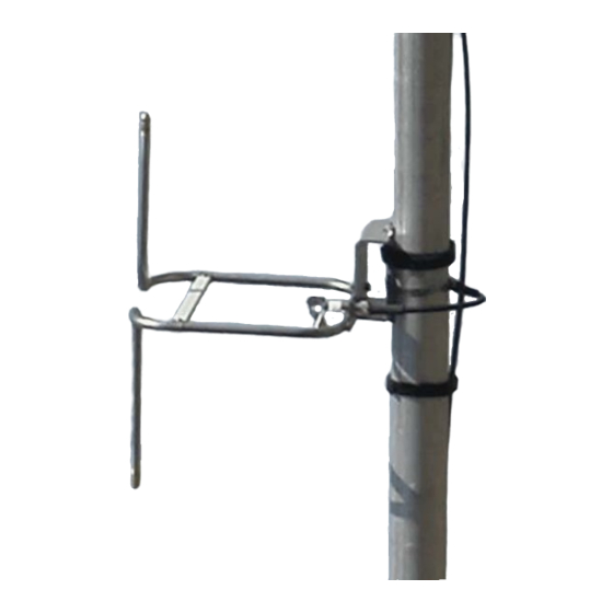
Installing the support The 6812DIN antenna is designed to mount on a customer-supplied vertical pipe, which in turn is mounted on the tower. Mounting is a little different for pipe side-mounted poles and top-mounted poles. -
Page 10: Installing The Radiators
Important! Feedstrap orientation is critical to performance. In general, all the feed- Install straps in a Model 6812DIN antenna will be oriented the same. each radiator in accordance with its stenciled bay numbers and its "up- arrow" sticker. Also, be very careful not to disturb or damage the feed strap when han- dling the radiator. -
Page 11: Installing The Interbay Cable Harness
Antenna Installation Figure 3. Installation of radiator without radome, exploded view e. Repeat for the remaining radiators, ensuring they are in the proper sequence and oriented correctly per the installation drawing. f. Sight vertically along the installation to ensure the radiators are aligned before finally securing them to the support pipe. - Page 12 Antenna Installation Figure 4. Radome backplate orientation The design of the antenna requires that the interbay feedline be about 50% longer than the bay-to-bay spacing. To protect the slack cable from wind and vibration damage, it must be wrapped and secured to the support pipe. CAUTION To ensure proper antenna performance, the excess feedline must be wrapped in a particular fashion, as shown in...
- Page 13 Antenna Installation Figure 5. Installation of radiator with radome, exploded view CAUTION If splicing tape is not applied correctly, water can get into the coax con- nections and affect the performance and reliability of your antenna. e. Apply splicing tape as follows (Figure 10 on page 10): (1) Make sure the fittings and coax are clean and dry.
- Page 14 Antenna Installation Figure 6. Installation of cable on top bay (and bottom bay if center-fed) Figure 7. Installation of cable on interior bay...
- Page 15 Antenna Installation Figure 8. Installation of cable on bottom bay, end-fed array Figure 9. Wrapping and securing the interbay cables (half-wave- spaced array only)
-
Page 16: (Top And Bottom Bays Only)
Figure 10. Proper and improper application of splicing tape (top and bottom bays only) (4) Inspect the connection carefully, ensuring that the joint is fully sealed. If more splicing tape is needed, simply add it to the existing wrap. It adheres well to itself. -
Page 17: Chapter 3 Installing The De-Icer System (If Applicable)
Remember that conditions may be favorable for icing on the tower, even if they are not on the ground. Shively Labs deicers are designed to prevent ice from forming on antenna ele- ments and are not designed to melt ice that has already formed. For this rea-... - Page 18 Installing the De-icer System (if applicable) Figure 11. De-Icer electrical schematic diagram NOTE Customer-supplied items are shown in broken lines. NOTE A liquid-tight conduit con- nector (3/8" conduit size by 1/2" hub size) for the harness entry tower junction box, is packed loose with the de- icer harness.
-
Page 19: De-Icer Installation
Installing the De-icer System (if applicable) Table 4. De-Icer specifications Heater Leg Heater Leg Resistance, (T1 or T2) Current Draw, amps 1-Bay 2-Bay 3-Bay 4-Bay 5-Bay 6-Bay 7-Bay 8-Bay, single circuit De-icer installation Installing the de-icer a. Install the main de-icer harness with its bay junction boxes as shown in Figure 11 on page 12 and Figure 12... - Page 20 Installing the De-icer System (if applicable) Figure 12. Bay junction box installation NOTE Wire nuts, cover with screws, and gaskets, and tie-wraps provided with the de-icer cable harness. Installing the thermostat If you are using a thermostat, you may locate and mount it at your discretion. We recommend mounting it as close as practical to the antenna.
- Page 21 Installing the De-icer System (if applicable) Table 5. Thermostat readings Reading Ambient Resistance = Resistance = Location Temperature 0 ohms infinite ohms (short circuit) (open circuit) Leg-to- Defective thermo- Ground stat or shorted leads Leg-to-Leg Above about 38° Defective thermo- F(3.3°...
-
Page 23: Chapter 4 Startup And Operation
The antenna System sweep Shively Labs strongly recommends that you perform a system sweep of your transmission line and antenna while you have the installation crew on site. (recommended) Should any problems arise later with your antenna, it will be extremely helpful to know what the system’s characteristics were when it was new. - Page 24 It is much easier to prevent ice formation than to remove a heavy coating. Shively Labs de-icer control If you have the Shively Labs de-icer control box and dual-setting thermostat, you have the choice of manual or automatic operation. There are three switch system settings: AUTOMATIC, OFF, and MANUAL.
-
Page 25: Chapter 5 Maintenance And Troubleshooting
22 shows a suggested log form. Physical inspection The antenna system should operate for years if properly installed and main- tained. Shively Labs recommends that as a minimum, the antenna should be at least once a year physically inspected In addition, inspect the antenna after severe weather events, and after climb- ers have been on the tower working on equipment above the antenna. -
Page 26: Return Policy
Troubleshooting Cantact Shively Labs if necessary to help find the cause of your problem. Out- side of 8:00 AM to 5:00 PM Eastern Time, call (207) 329-5118. Internal arcing Internal arcing is caused by physical damage to transmission line, feedline, or radiators. - Page 27 Maintenance and Troubleshooting It is important to recognize, however, that apparent changes in coverage may be due to subjective factors or faults of the receiving equipment. Before doing more than checking the VSWR, be sure that an actual coverage change has occurred.
-
Page 28: Sample Maintenance Log
Maintenance and Troubleshooting Sample maintenance DATE DE-ICER CURRENT VSWR OBSERVATIONS (or resistance) Visual Inspection of Antenna, Obstruction Lighting; Hard- ware Checked; Tower Repairs Accomplished; etc. BLACK NEUT (b-neut) (red-bl) (r-neut)
Need help?
Do you have a question about the 6812DIN and is the answer not in the manual?
Questions and answers