Table of Contents
Advertisement
Quick Links
Dear Client
Thank you for Purchasing our SMG2000B Double Clamps
Digital Phase Meter. Please read the manual in detail prior to first
use, which will help you use the equipment skillfully.
company's products continually, so there may be
slight differences between your purchase equipment
and its instruction manual. You can find the changes
in the appendix. Sorry for the inconvenience. If you have further
questions, welcome to contact with our service department.
may bring voltage, when you plug/draw the test wire or
power outlet, they will cause electric spark. PLEASE
CAUTION RISK OF ELECTRICAL SHOCK!
Company Address:
T4,No. 41, High-tech 2 Road,East Lake High-tech Development Zone,
Wuhan
Sales Hotline: 86-27- 87457960
After Service Hotline: 86-27- 87459656
Fax: 86-27- 87803129
E-mail: qiao@hvtest.cc
Website: www.hvtest.cc
Our aim is to improve and perfect the
The input/output terminals and the test column
1
Advertisement
Table of Contents

Related Manuals for HVTest SMG2000B


Summary of Contents for HVTest SMG2000B
- Page 1 Dear Client Thank you for Purchasing our SMG2000B Double Clamps Digital Phase Meter. Please read the manual in detail prior to first use, which will help you use the equipment skillfully. Our aim is to improve and perfect the company's products continually, so there may be slight differences between your purchase equipment and its instruction manual.
- Page 2 SERIOUS COMMITMENT All products of our company carry one year limited warranty from the date of shipment. If any such product proves defective during this warranty period we will maintain it for free. Meanwhile we implement lifetime service. Except otherwise agreed by contract.
- Page 3 shock, the grounding conductor must be connected to the ground. Make sure the product has been grounded correctly before connecting with the input/output port. Pay Attention to the Ratings of All Terminals To prevent the fire hazard or electric shock, please be care of all ratings and labels/marks of this product.
- Page 4 -Security Terms Warning: indicates that death or severe personal injury may result if proper precautions are not taken Caution: indicates that property damage may result if proper precautions are not taken.
-
Page 5: Table Of Contents
Contents I. Overview········································································ 6 II. Intrinsic Error·································································· 6 III. Operating Error ······························································ 7 IV. Other Technical Specifications·········································· 8 V. Product Structure···························································· 9 VI. Notes ··········································································· 9 VII. Operation Instructions··················································· 10 VIII. Adjust the display························································ 12 IX. Battery replacement ······················································ 12... -
Page 6: Overview
I. Overview SMG2000B Double Clamp Digital Phase Meter is specially designed for measuring voltage, current and phase. It is characterized by high precision, low price, portable hand-held and dual-channel input measuring. It’s easy to measure the phase between U-U, I-I and U-I, identify the inductive/capacitive... -
Page 7: Operating Error
7) External reference frequency electromagnetic interference: Should be avoided 2. Limits of Intrinsic Error 1) AC Voltage(see Table 1) Table 1:Error of AC Voltage Measure range Resolution Limits of intrinsic error 0.01V ±(1.2%RD+2) 200V 0.1V ±(1.0%RD+2) 500V ±(1.2%RD+2) Input Impedance:All measure ranges input 2MΩ 2)AC current(see Table 2)... -
Page 8: Other Technical Specifications
5) Position of Measured current carrying conductor in clamp jaw: optional position. 6) Amplitude range of measured signal when measuring phase: Phase U1-U2: 30V~500V Phase I1-I2: 10mA~10.00A Phase U1-I2 or I1-U2: 10V~500V、10mA~10.00A 7) External reference frequency electromagnetic interference: Should be avoided 2. -
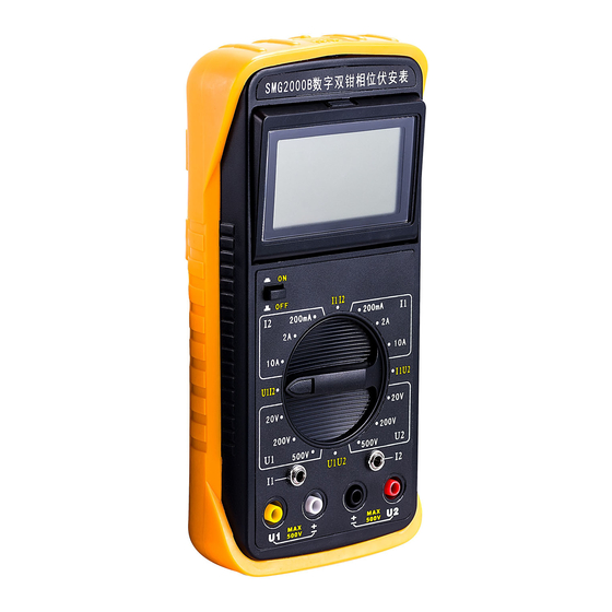
Page 9: Product Structure
V. Product Structure 1.insulating protection casing 2.three and half bits LCD 3.ON/OFF button 4.measure range switch 5.current clamp jack(2 loops) 6.voltage input jack(2 loop) 7.current clamp jaw 8.current clamp jaw 9.down-lead of current clamp 10.crocodile clip(4 pieces) 11.test lead(4 pieces) 12.shorting stub(1 piece)... -
Page 10: Operation Instructions
VII. Operation Instructions Press the ON/OFF button; turn the measure range switch to choose the correct testing parameters and range. 1. Measuring AC voltage Turn the rotary switch to 500V in U1 region, and connect the measured voltage into jack U1, you can measure. If the measured value is less than 200V, you can directly turn the switch to 200V in U1 region to obtain better measurement accuracy. - Page 11 4. Measuring phase angle between two current When measuring the phase angle that I2 lags I1, turn the rotary switch to parameter I1I2.Under measurement, you can turn the rotary switch clockwise to different measure ranges in I1 region to measure input current I1, or turn the rotary switch anticlockwise to different measure ranges in I2 region to measure input current I2.
-
Page 12: Adjust The Display
7. Judge phase sequence of the three-phase four-wire system Turn the rotary switch to U1U2, connect phase A to jack U1, connect phase B to jack U2, connect Zero Line to the two input loop jacks “±”. If the measured phase value is approximately 120°, it is positive phase sequence. If the measured phase value is approximately 240°, it is negative phase sequence.
Need help?
Do you have a question about the SMG2000B and is the answer not in the manual?
Questions and answers