
Subscribe to Our Youtube Channel
Related Manuals for Alpha DCX LP


Summary of Contents for Alpha DCX LP
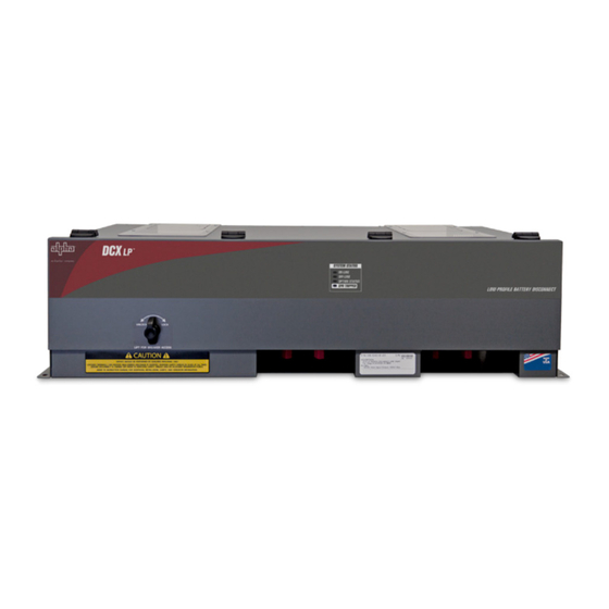
- Page 1 DCX LP ™ Low Profile DC Battery Disconnect System For Unigy II 6AVR125-33 NEBS ® Technical Manual Effective: March 2021...
- Page 2 Safety Notes Alpha Technologies Services, Inc. considers customer safety and satisfaction its most important priority. To reduce the risk of injury or death and to ensure continual safe operation of this product, certain information is presented differently in this manual. Alpha tries to adhere to ANSI Z535 and encourages special attention and care to information presented in ®...
- Page 3 Images contained in this manual are for illustrative purposes only. These images may not match your installation. Operator is cautioned to review the drawings and illustrations contained in this manual before proceeding. If there are questions regarding the safe operation of this powering system, please contact Alpha Technologies Services, Inc. or your nearest Alpha representative.
-
Page 4: Table Of Contents
Appendix A: Mechanical Drawings ........13 A.1 DCX LP... -
Page 5: Purpose And Applicability
The secondary function is to provide a service disconnect in order to maintain batteries or to shut down the battery source connection in an emergency. The DCX LP system features a low profile design to maximize installation flexibility in space constrained applications. -
Page 6: Monitoring Options
Unpacking and Inspection The DCX LP unit was carefully packaged at the factory to withstand the normal rigors of shipping. However, you should carefully inspect the box and contents to confirm that no damage has occurred in transit. Most shipping carriers require notification of shipping damage within twenty-four hours of delivery, and it is the responsibility of the recipient to inspect the shipment immediately upon receipt. -
Page 7: Installation
Installation CAUTION! FOR SAFETY PURPOSES, PRIOR TO THE INSTALLATION OF THE DCX LP UNIT, DISCONNECT SEVERAL SERIES BUS CONNECTIONS OF THE STRING TO ENSURE THE TOP NEGATIVE TERMINAL IS NOT CONNECTED IN SERIES TO THE REST OF THE STRING. THIS IS CRITICAL FOR INSTALLATION WORK TO BE DONE SAFELY WITHOUT VOLTAGE PRESENT. -
Page 8: 4�2 Mounting Procedure
Figure 7. DCX LP unit mounting alignment Figure 7)� Step 4. Secure the DCX LP unit to the side rails using (4) 1/4-20 x 5/8" hex screws and washers located in the mounting kit. A split washer should separate the screw head and flat washer. -
Page 9: Termination Bus Plates
6-32 x 3/8 pan head screws. The shields are to be attached to the isolation bars surrounding the termination plates. Step 6. Ensure that the DCX LP unit is securely mounted on the top of the battery stack. Step 7. Once mechanical mounting is complete, the remaining steps include electrical connections�... -
Page 10: Emergency Power Off Option
Step 4. Flip on the DCX LP breaker. The “ON-LINE” blue LED should light and the unit should be functional. Step 5. To test the EPO trip, push in the remote EPO switch; the DCX LP breaker should trip to the off position and the ON-LINE LED will go out and the OFF-LINE LED will turn on. -
Page 11: Output Cable Installation
Step 4. After servicing, replace the clear cover(s) with the screws provided. This completes the DCX LP product installation procedure. Prior to connection of the battery series cell connections or connection of the output cable ends to rectifier bays or load devices, perform several safety checks and verification of correct wiring polarity and installation. -
Page 12: Product Specifications
Models and Accessories Table 6. Model Configurations DESCRIPTION PART NUMBER DCX LP; 1200A Breaker; Low Profile DC Battery Disconnect System for Unigy II 6AVR125- C016-1540-10 33 NEBS DCX LP; 1200A Breaker; Low Profile DC Battery Disconnect System for Unigy II 6AVR125- C016-1545-10 33 NEBS;... -
Page 13: Appendix A: Mechanical Drawings
Appendix A: Appendix A: Mechanical Drawings Mechanical Drawings A.1 DCX LP DCX LP Battery Disconnect System and East Penn Batteries Unigy Battery Disconnect System and East Penn Batteries Unigy II II ™ ™ ® ® 6AVR125-33 NEBS Battery Stack with Front and Side Dimensions 6AVR125-33 NEBS Battery Stack with Front and Side Dimensions 28.223... - Page 14 C048-720-30 Rev. B (03/2021)
- Page 15 C048-720-30 Rev. B (03/2021)
- Page 16 Tel.: Toll Free North America: +1 800 322 5742 | Outside US: +1 360 647 2360 | Technical Support: +1 800 863 3364 For more information visit our website at: www.alpha.com © 2021 Alpha Technologies Services, Inc. All Rights Reserved. Trademarks and logos are the property of Alpha C048-720-30 Rev. B (03/2021)
Need help?
Do you have a question about the DCX LP and is the answer not in the manual?
Questions and answers