Table of Contents
Advertisement
Quick Links
P/N 126871-01 Rev.A 02/2014
P126871-01
INSTALLER: Leave this manual with the appliance.
CONSUMER: Retain this manual for future reference.
This appliance may be installed in an aftermarket permanently located, manufactured (mobile) home, where not
prohibited by local codes. This appliance is only for use with the type of gas indicated on the rating plate. This
appliance is not convertible for use with other gases.
This is an unvented gas-fired heater. It uses air (oxygen) from the room in which it is installed. Provisions
for adequate combustion and ventilation air must be provided. Refer to Air for Combustion and Ventilation
section on page 6 of this manual.
WARNING: If the information in these instructions is not followed exactly, a fire or explosion may result
causing property damage, personal injury or loss of life.
— Do not store or use gasoline or other flammable vapors and liquids in the vicinity of this or any other
appliance.
— WHAT TO DO IF YOU SMELL GAS:
• Do not try to light any appliance.
• Do not touch any electrical switch; do not use any phone in your building.
• Immediately call your gas supplier from a neighbor's phone. Follow the gas supplier's instructions.
• If you cannot reach your gas supplier, call the fire department.
— Installation and service must be performed by a qualified installer, service agency or the gas supplier.
Installation and Operation Instructions
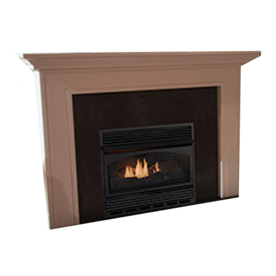
Superior™ Unvented (Vent-Free) Compact Fireplace
Models
VCM3026ZTP
VCM3026ZTN
Advertisement
Table of Contents

Related Manuals for Superior Fireplaces VCM3026ZTP


Summary of Contents for Superior Fireplaces VCM3026ZTP
- Page 1 Installation and Operation Instructions Superior™ Unvented (Vent-Free) Compact Fireplace P/N 126871-01 Rev.A 02/2014 Models VCM3026ZTP VCM3026ZTN P126871-01 INSTALLER: Leave this manual with the appliance. CONSUMER: Retain this manual for future reference. This appliance may be installed in an aftermarket permanently located, manufactured (mobile) home, where not prohibited by local codes.
-
Page 2: Table Of Contents
TABLE OF CONTENTS Safety ..............2 Cleaning and Maintenance ........ 23 Local Codes............4 Troubleshooting ..........24 Product Identification ........... 4 Specifications ............ 28 Product Features ..........5 Service Hints ............. 28 Unpacking............5 Technical Service..........28 Assembly ............. 5 Replacement Parts .......... - Page 3 SAFETY Continued Keep the appliance area clear WARNING: Any change to and free from combustible this heater or its controls can materials, gasoline, and other be dangerous. flammable vapors and liquids. WARNING: Do not allow fans 1. This appliance is only for use with type of gas indicated on rating plate.
-
Page 4: Local Codes
SAFETY Continued 10. This fireplace needs fresh air ventilation to 14. Turn off and unplug fireplace and let run properly. This fireplace has an Oxygen cool before servicing. Only a qualified Depletion Sensing (ODS) safety shutoff service person should service and repair system. -
Page 5: Product Features
PRODUCT FEATURES SAFETY PILOT THERMOSTATIC HEAT CONTROL This fireplace has a pilot with an Oxygen This fireplace has a thermostat sensing bulb Depletion Sensing (ODS) safety shutoff and a control valve. The thermostat will auto- system. The ODS/pilot is a required feature matically modulate the heat output to maintain for vent-free room fireplaces. -
Page 6: Air For Combustion And Ventilation
ASSEMBLY Continued 1. Locate four black phillips sheet metal Louver screws from the hardware packet. 2. Rotate hood as shown in Figure 3. Make Hood Tabs sure hood tabs point toward fireplace. 3. Insert hood tabs between baffle and lou- vers (see Figure 3). - Page 7 AIR FOR COMBUSTION AND VENTILATION Continued c. caulking or sealants are applied to 2. Multiply the space volume by 20 to determine the maximum Btu/Hr the space can support. areas such as joints around window and door frames, between sole plates ________ (volume of space) x 20 = (Maxi- and floors, between wall-ceiling joints, mum Btu/Hr the space can support)
- Page 8 AIR FOR COMBUSTION AND VENTILATION Continued Ventilation Air From Outdoors WARNING: If the area in which Provide extra fresh air by using ventilation the heater may be operated does grills or ducts. You must provide two perma- not meet the required volume for nent openings: one within 12"...
-
Page 9: Installation
INSTALLATION IMPORTANT: Vent-free fireplaces add mois- NOTICE: This heater is intended ture to the air. Although this is beneficial, for use as supplemental heat. installing fireplace in rooms without enough Use this heater along with your ventilation air may cause mildew to form from primary heating system. - Page 10 INSTALLATION Continued LOCATING FIREPLACE Note: When installing fireplace directly on carpeting, tile or other combustible material, WARNING: Maintain the other than wood flooring, the fireplace shall be installed on a metal or wood panel extending minimum clearances shown the full width and depth of the fireplace. in Figures 6 and 7.
- Page 11 INSTALLATION Continued IMPORTANT: When finishing your firebox, WARNING: If pre-wiring, do combustible materials not connect wiring to any electri- WARNING: Do not allow any cal source at this time. combustible/noncombustible Install fireplace electrical outlet materials to overlap the firebox and connect wiring to outlet front facing.
- Page 12 INSTALLATION Continued OPTIONAL MANTEL INSTALLATION WARNING: Never modify or Refer to instructions provided with the mantel cover the louvered slots on the for assembly instructions. Refer to the follow- front of the firebox. ing instructions for system installation. Refer to instructions on page 6 for hood assembly. Mantel Clearances for Built-In Blower accessory should be installed prior to Installation...
- Page 13 INSTALLATION Continued Checking Gas Connections, page 18. in slot on mitered edge of top trim (see Figure 14). 10. Carefully insert fireplace into cabinet mantel (see Figure 13). Be careful not to 5. Slide other end of adjusting plate/shim scratch or damage hearth base or cabinet in slot on mitered edge of side trim (see mantel.
- Page 14 INSTALLATION Continued screwdriver, the screen, log set, and 4. Carefully disconnect green and white branch support must be removed so a wires at their insulated connectors. longer screwdriver may be used. See 5. In top of heater cabinet, locate 4 mounting Connecting Equipment Shutoff Valve to holes on outer casing.
- Page 15 INSTALLATION Continued Note: When switch is in AUTO position, 4. A licensed electrician must follow the wir- fan will start after heater has run for a ing diagram to connect incoming electri- few moments. Fan will continue to run cal supply to fan kit wiring harness (see Figure 19).
- Page 16 INSTALLATION Continued Blower Bracket Wire Harness Assembly CAUTION: Never connect pro- pane/LP fireplace directly to the propane/LP supply. This fireplace Screw requires an external regulator (not supplied). Install the external regulator between the fireplace Switch Plate and propane/LP supply. Power Switch Cord Outlet...
- Page 17 INSTALLATION Continued Installation must include an equipment shutoff 2. Remove screws that attach branch sup- valve, union, and plugged 1/8" NPT tap. Lo- port to fireplace (see Figure 23). Carefully cate NPT tap within reach for test gauge hook lift up branch support and remove from up.
- Page 18 INSTALLATION Continued 6. Replace branch support back into fire- PRESSURE TESTING GAS SUPPLY place. Feed flexible gas line into fireplace PIPING SYSTEM base area while replacing branch support. Test Pressures In Excess Of 1/2 PSIG Make sure the entire flexible gas line is (3.5 kPa) in fireplace base area.
-
Page 19: Operation
INSTALLATION Continued Equipment PRESSURE TESTING FIREPLACE GAS Shutoff Valve CONNECTIONS 1. Open equipment shutoff valve (see Figure Propane/LP 25, page 18). Supply Tank 2. Open main gas valve located on or near gas meter for natural gas or open pro- pane/LP supply tank valve. - Page 20 OPERATION Continued qualified service person or gas supplier for INSTRUCTIONS repairs. Until repairs are made, light pilot with match. To light pilot with match, see Manual Lighting Procedure, page 21. WARNING: You must operate 7. Keep control knob pressed in for 30 sec- this fireplace with the fireplace onds after lighting pilot.
- Page 21 OPERATION Continued TO TURN OFF GAS MANUAL LIGHTING TO APPLIANCE PROCEDURE 1. Follow steps 1 through 5 under Lighting Shutting Off Fireplace Instructions, page 20. 1. Turn control knob clockwise to the 2. With control knob pressed in, strike match. OFF position.
-
Page 22: Inspecting Burner
INSPECTING BURNER BURNER FLAME PATTERN Check pilot flame pattern and burner flame pattern often. Figure 33 shows a correct burner flame pat- tern. Figure 34 shows an incorrect burner PILOT FLAME PATTERN flame pattern. The incorrect burner flame Figure 31 shows a correct pilot flame pattern. pattern shows sporadic, irregular flame tip- Figure 32 shows an incorrect pilot flame pat- ping. -
Page 23: Cleaning And Maintenance
CLEANING AND MAINTENANCE 4. Check injector holder located at end of WARNING: Turn off fireplace burner tube again. Remove any large and let cool before cleaning. particles of dust, dirt, lint, or pet hair with a soft cloth or vacuum cleaner nozzle. 5. -
Page 24: Troubleshooting
TROUBLESHOOTING WARNING: Turn off heater and let cool before servicing. Only a qualified service person should service and repair heater. CAUTION: Never use a wire, needle, or similar object to clean ODS/pilot. This can damage ODS/pilot unit. Note: All troubleshooting items are listed in order of operation. OBSERVED PROBLEM POSSIBLE CAUSE REMEDY... - Page 25 TROUBLESHOOTING Continued OBSERVED PROBLEM POSSIBLE CAUSE REMEDY ODS/pilot lights but flame 1. Control knob not fully 1. Press in control knob fully goes out when control knob pressed in is released 2. Control knob not pressed in 2. After ODS/pilot lights, keep long enough control knob pressed in 30 seconds...
- Page 26 TROUBLESHOOTING Continued OBSERVED PROBLEM POSSIBLE CAUSE REMEDY Slight smoke or odor during 1. Residues from manufactur- 1. Problem will stop after a few initial operation ing processes hours of operation Fireplace produces a whis- 1. Turning control knob to HI 1.
- Page 27 TROUBLESHOOTING Continued WARNING: If you smell gas • Shut off gas supply. • Do not try to light any appliance. • Do not touch any electrical switch; do not use any phone in your building. • Immediately call your gas supplier from a neighbor’s phone. Fol- low the gas supplier’s instructions.
-
Page 28: Specifications
SPECIFICATIONS VCM3026ZTP VCM3026ZTN • Rating (Variable): 14,000/26,000 Btu/Hr • Rating (Variable): 14,000/26,000 Btu/Hr • Gas Type: Propane/LP Gas Only • Gas Type: Natural Gas Only • Ignition: Piezo • Ignition: Piezo • Pressure Regulator Setting: 8" W.C. • Pressure Regulator Setting: 3" W.C. -
Page 29: Accessories
ACCESSORIES CORNER MANTEL WITH FULL NOTICE: All accessories may HEARTH BASE not be available for all fireplace C26TU - Unfinished, Traditional Design models. C26TO - Oak Finished, Traditional Design Purchase these accessories from your local C26GO - Oak Finished, Georgian Design dealer. -
Page 30: Parts
PARTS MODELS VCM3026ZTP (SHOWN) AND VCM3026ZTN 12-1 www.SuperiorFireplaces.US.com 126871-01A... - Page 31 PARTS This list contains replaceable parts used in your fireplace. When ordering parts, follow the instructions listed under Replacement Parts on page 28 of this manual. NO. PART NO. DESCRIPTION 102633-02 Outer Casing Top • • 102624-02 Outer Casing • •...
-
Page 32: Warranty
Innovative Hearth Products Superior™ Brand Gas Fireplaces, Stoves and Inserts 20 Year Limited Warranty THE WARRANTY Innovative Hearth Products ("IHP") 20 Year Limited Warranty warrants your Superior™ Brand gas fireplace, Stove or Insert ("Product") to be free from defects in materials and workmanship at the time of manufacture. - Page 33 WARRANTY KEEP THIS WARRANTY Model (located on product or identification tag) _____________________________ Serial No. (located on product or identification tag) __________________________ Date Purchased __________________________ Keep receipt for warranty verification. www.SuperiorFireplaces.US.com 126871-01A-01...
- Page 34 1508 Elm Hill Pike, Suite 108 Nashville, TN 37210 126871-01 1-800-655-2008 Rev. A www.IHP.US.com 02/14 P126871-01...
Need help?
Do you have a question about the VCM3026ZTP and is the answer not in the manual?
Questions and answers