Table of Contents
Advertisement
Advertisement
Table of Contents

Related Manuals for Nature's Comfort NCB-275G


Summary of Contents for Nature's Comfort NCB-275G
- Page 1 Installation and Operating Manual for 2014 NCB-275G NCB-325G NCB-400G Non-Pressurized Outdoor Wood Boiler Manufactured by Nature’s Comfort LLC. Made in the USA www.wood-heating-solutions.com Built Like A Tank With Laser Precision SAVE THESE INSTRUCTIONS Revision 2014-2.0...
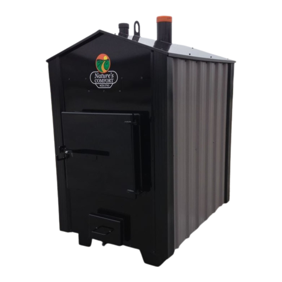
- Page 3 INTRODUCTION Thank you and congratulations on the purchase of your new Nature’s Comfort boiler! With the purchase of this Nature’s Comfort boiler, you can now appreciate the high degree of craftsmanship and reliability that are a result of every boiler being carefully hand-built as well as taking control of heating your home.
-
Page 5: Table Of Contents
Table of Contents I. General Information A. Terminology ................6 D. Safety Precautions ..............7 B. Clearance to Combustibles Required ......6 E. Controls & Plumbing Connections ......... 8 C. Boiler Dimensions & Specs ..........6 F. Heating the Home ..............9 II. -
Page 6: General Information
54” 27”W x 25.5”H 39” X 11.75”X 4” NCB-325G 28.5cu/ft oval 30”Wx46”H 54” 27”W x 25.5”H 39” X 11.75”X 4” NCB-400G 40.0cu/ft oval Steel thickness Water Jacket Firebox 7ga. (approx. 3/16”) ¼” NCB-275G, 325G & 400G Page 6 of 31... -
Page 7: Safety Precautions
Safety Precautions Do not operate this equipment for anything other than its intended purpose or for anything other than in accordance with the instructions contained in this manual and all other instructions accompanying the boiler. It is important to observe safety precautions to protect yourself and others from possible injury. -
Page 8: Controls & Plumbing Connections
Controls & Plumbing Connections The outside boiler has a hot water thermostat (aquastat) with a thermocouple that is inserted into a brass drywell that senses the water temperature of the unit. When the temperature of water in the boiler falls below the “low”... -
Page 9: Heating The Home
Heating the Home The NCB boiler saves energy and provides the most comfortable heating available. It heats the home by burning seasoned hardwood to heat a firebox surrounded by a steel tank filled with water. The boiler is non-pressurized with an atmospheric vent and includes an easy-to-read water jacket float indicator. -
Page 10: Installing The Boiler
III. Installing Boiler Installation is to be performed by a qualified installer and shall comply with all the requirements of the authority having jurisdiction over the installation. A. Location of Boiler The NCB boiler must be located to comply with the clearance requirements. Keep the firebox door positioned so as not to point toward a structure so all fire danger is removed from the home. -
Page 11: Chimney, Extensions & Rain Cap
If the unit is located in a windy area, it is recommended to install a non-combustible type of skirting around the feet and control area. B. Chimney: A 6” stainless steel rain cap must be purchased separately for installation and can be obtained from Nature’s Comfort or your dealer. -
Page 12: Plumbing Hookup
D. Plumbing Hook Up Plumbing connections should be well insulated after installation. Cover bottom access holes as well. Minimum pipe size permitted is 1”. Install the outgoing pex line on the pump flange that is already mounted to the lower end of the circulation pump. Install the return line on the 1-1/4” fitting located in the top-middle of the rear control area. - Page 13 Use this example diagram if you have a typical, basic 4 wire system: Use the example drawing below if you have a 2 wire system or the thermostat is the advanced computerized type that communicates back and forth between the furnace (typically found on heat pump systems).
-
Page 14: Adding Bypass Valves
G. Adding Bypass Valves Adding a bypass valve system (3 valves, 2 T’s and unions) at each heat exchanger is a good idea so that if there is a potential problem such as a stopped up heat exchanger, it can be diagnosed & serviced easily as well as being used for a summer bypass as explained in the “operation”... -
Page 15: Installing In A Small Plenum
Slide the heat exchanger into the hole for a test fit. Ideally the header and tubes (F) should stick out of the plenum. While test fitting try to determine how much tape is needed around the frame of the heat exchanger to seal and keep air from flowing around it. -
Page 16: Adjusting Plenum Air Flow
Crimp the sheet metal to the edge of the heat exchanger (item G) using channel-lock pliers. This not only forms a virtually airtight seal, but also supports the heat exchanger as well. J. Adjusting Plenum Air Flow The motors on most force air furnaces have three speeds to provide various rates of air movement. Please consult a local furnace specialist if you want to change the airflow of an existing furnace system. - Page 17 The electrical diagram on the next page shows a typical control setup for operating a 2 zone radiant system for a new radiant installation that does not use an existing hydronic furnace. Part numbers are noted on each item for ordering from Nature’s Comfort. Page 17 of 31...
- Page 18 Page 18 of 31...
-
Page 19: Filling The Boiler With Water
L. Filling the Boiler with Water Inspection: Before filling, inspect the pump shaft by removing the large silver screw to expose the top of the shaft and turn back and forth with a screw driver to make sure the shaft was not broken during shipping. -
Page 20: Heating Domestic Water, Pools And Spa's
Option 3: (Best but more hassle and messy) Purchase a tube of high temperature caulk from your dealer or Nature’s Comfort and brush over the entire surface area of the rope seals to permanently seal out smoke and creosote. Place a 2” strip of wax paper over this. Over-extend the latch open and bounce the door/ash pan closed, then leave open to fully cure before starting a fire to get a custom, long term seal. -
Page 21: Heating A Pool Or Spa
B. Heating a Pool or Spa Please contact a local pool/spa specialist if this boiler is to be used to heat a pool or spa. A stainless steel (or 90/10 copper/nickel alloy) tube & shell water-to-water heat exchanger must be used to transfer heat from the boiler to a pool or spa since the chemicals used in a pool/spa are destructive to the boiler. -
Page 22: Operation
IV. Operation A. Wood Requirements For maximum efficiency and burn times only burn wood that has been cut, split and seasoned for 12-24 months, sheltered from rain and snow. The wood should be split 6-8” in diameter and cut 12- 16”... -
Page 23: Blower Output Damper
Caution! Flammable gases fill the firebox when idling. Pause at blowback catch for 30 seconds and then stand to the side when fully opening until smoke dissipates enough to see inside. Failure to do this can result in possible flashback to the face from gases igniting. Always stir ash to prevent “caking”... -
Page 24: Maintenance
V. Maintenance A. Cleaning Wear heavy gloves and clothing and safety glasses as metal, coals and ashes will be hot. Moisture combined with ash will eat through a boiler in short order and ash corrosion is NOT covered under warranty. Clean ash out frequently and stir (break up) ash in ALL areas (especially corners) daily to prevent any “caking”... -
Page 25: Pump
Inspection Check the rope seals on all doors and covers periodically during the heating season or when cleaning ash from the boiler as they will compress. If any amount of smoke is seeping out, damage to a door or cover will occur if adjustment is not made immediately to tighten the rope seal. -
Page 26: End Of Season Care
broken during shipping. Broken shafts are not covered under warranty unless found and noted before installation and startup. Startup: Make sure the lines are filled and prime the pump by cracking the upper pump flange to bleed the air out of the impeller and volute. IMPORTANT: The large, silver bleeder screw must also be removed from the pump before running for the first time to bleed all air from the After priming the pump, remove and leave the... -
Page 27: Going Away
Re-seal caulk on all jambs. Coat entire threaded portion of all bolts for doors and covers with a never-seize product. 5. Plumbing: Ensure fittings are tight at all locations. Over-fill so float pointer is 4” above rubber cap, re-seal caulk. 6. -
Page 28: Trouble Shooting
Trouble Shooting Problem Cause Solution Boiler does not come up to Green or soft wood is being used Use properly seasoned hard wood temperature. Wind blowing under boiler Take one or two inches of hard board insulation and place under boiler between legs then add non-combustible spacers between ground to hold up insulation Change to a larger pump, use min 1”... -
Page 29: Warranty
Nature's Comfort's wood boilers are not meant to be your sole source of heat. It is the responsibility of the owner to have a backup system in place. If you do not have a backup source of heat you are at risk of damage due to lack of heat. Nature's Comfort will not warranty or be responsible for any damage caused by lack of heat at your premises or for any cost incurred from using a backup heat system in the event of a boiler failure. -
Page 30: Warranty Cards
Customer Warranty Card Please fill in the following information and keep for future reference. ___________________________________ Name: (First) (Last) ___________________________________ Address: (Street) ___________________________________ (City) (State) (Zip) _________ ________________________ Phone: (Area Code) (Number) Model & Serial Number: ____________________________ Date of Purchase: ____________________________ Dealer Purchased From: __________________________________________________ (Business &... - Page 31 Mail-in Warranty Card (information is never shared or sold) All fields must be filled out Name: _________________________________________________________________ (First) (Middle) (Last) Address: _________________________________________________________________ (Street) _________________________________________________________________ (City) (State) (Zip) Phone Number: ________________ ___________________________ (Area code) (Number) E-mail Address: _______________________________________________ (For contact purposes only) Model &...
Need help?
Do you have a question about the NCB-275G and is the answer not in the manual?
Questions and answers