
Subscribe to Our Youtube Channel
Related Manuals for Chauvin Arnoux THYRITOP 600 Series


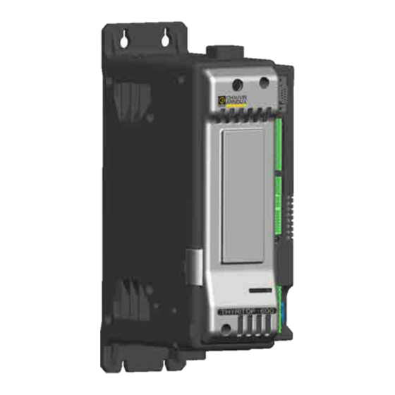
Summary of Contents for Chauvin Arnoux THYRITOP 600 Series
- Page 1 GB - Installation and operation manual THYRITOP SERIE 600 40 to 600 A power controllers...
-
Page 2: Table Of Contents
TABLE OF CONTENTS Table of Contents ............. 1 3.4.4. PORT2 (optional Fieldbus) type P: Modbus RTU / Profibus DP - connectors S4, S5 .......28 Preface ..............3 3.4.5. PORT2 (optional Fieldbus) type C: Modbus RTU / CANopen - connectors S4, S5 ........29 Device data and initial checks ............3 3.4.6. - Page 3 3.7.4. Connection example for two-phase Thyritop 600 (2PH) for a three-phase star load without neutral ....58 3.7.5. Connection example for two-phase Thyritop 600 (2PH) for a three-phase star load without neutral with trans- former .................59 3.7.6. Connection example for two-phase Thyritop 600 (2PH) for a three-phase closed delta load ......61 3.7.7.
-
Page 4: Preface
Instructions for Use and Warnings in addition to the product. Serial number Finished product ® CODE LISTED RoHS E243386 code PYROCONTROLE - CHAUVIN ARNOUX GROUP SCCR RMS SYM 6 Bis Av Docteur Schweitzer 100KA / 600V 69881 MEYZIEU Cedex FRANCE PXXXXXX Order code TYPE CODE:... -
Page 5: Typographical Conventions Used In The Manual
Typographical conventions used in the manual Pay attention when the following symbols are found in the manual. This indicates particularly important information relevant to correct product operation or safety, or This indicates a suggestion that could be helpful provide instructions that must be strictly followed. for better use of the device. -
Page 6: General Description
1.1.1. Profile values. Some functions of the Thyritop 600 range are designed for The Advanced Power Controllers of the Thyritop 600 series specific applications and problems: are self-contained units with the capability of controlling • For systems with three-phase transformers, any... -
Page 7: Configuration
For temperature values: The Thyritop 600 controllers can be equipped with a Tyritop • Exclusive continuous temperature measurement of remote portable programming terminal, powered by the all power terminals with an alarm for loose terminal controller, which permits monitoring of process variables diagnosis. -
Page 8: Thyritop 600
1.4. Thyritop 600 Main features • Single/two/three-phase, 40 A to 600 A • Operating voltages 480 Vac, 600 Vac and 690 Vac • Firing mode configurable to “Zero crossing” (Fixed Cy- cle, Burst Firing, Half Single Cycle) and “Phase angle” •... -
Page 9: Main Elements Of The Thyritop 600, 400 A
1.4.2. Main elements of the Thyritop 600, 400 A ... 600 A models Figure 2 - Elements of the Thyritop 600 400 A ... 600 A models Auxiliary output connector 10. Protective cover on internal fuse and line/load connec- Relay output connector tions Power supply connector and 24 V digital inputs 11. -
Page 10: Configuration Dip Switches
1.6. Configuration dip switches • DIP switch 6: loading of the default values for the The DIP switches are used to set the configura- tion of the Advanced Power Controller. configuration selected with DIP switches 1 to 7. See paragraph “1.6.2. Initialisation procedure and loading The functions associated with the DIP switches of default values”... -
Page 11: Led Indicator Functions
1.7. LED indicator functions Colour Description green Run: flashing during regular operation Error status: activated in the presence of an alarm yellow Digital input 1 status yellow Digital input 2 status yellow Out 1 Master module (M) power output status yellow Out 2 expansion 1 (E1) power output status, managed only with Thyritop 600 versions 2PH and 3PH yellow... -
Page 12: Dimensions
1.8. Dimensions 1.8.1. Dimensions of Thyritop 600, 40 A ... 300 A models Single-phase Side view with keypad Side view without keypad All dimensions in mm Figure 3 - Dimensions of Thyritop 600 40 ... 300 A (single-phase) Two-phase and Three-phase All dimensions in mm Figure 4 - Dimensions of Thyritop 600 40 ... -
Page 13: Dimensions Of Thyritop 600, 400 A
1.8.2. Dimensions of Thyritop 600, 400 A ... 600 A Single-phase All dimensions in mm Figure 5 - Dimensions of Thyritop 600 400 ... 600 A (single-phase) Two-phase All dimensions in mm Figure 6 - Dimensions of Thyritop 600 400 ... 600 A (two-phase) 906121687 « THYRITOP 600 »_05-2021_GB_page 12... - Page 14 (Three-phase) All dimensions in mm Figure 7 - Dimensions of Thyritop 600 400 ... 600 A (three-phase) 906121687 « THYRITOP 600 »_05-2021_GB_page 13...
-
Page 15: Installation And Power Supply
INSTALLATION AND POWER SUPPLY Caution! The installation of the devices described Caution! If even one of the above-mentioned in this manual must be carried out by qualified requirements (qualified technician, device intact, technicians, following current laws and regulations configuration compatible with needs) is not met, and in accordance with the instructions given in suspend installation and contact your Pyrocontrole this manual. - Page 16 Hot zone Outgoing air > 10 mm > 10 mm flow Air deflector Incoming air flow Cold zone Figure 8 - Thyritop 600 minimum ventilation spaces Single-phase (1 PH) Two-phase (2 PH) Three-phase (3 PH) 87.2 87.2 87.2 4 holes 6 holes 4 holes 31.5...
-
Page 17: Power Supply
Thyritop 600. A filter connected between the power supply line and the The Thyritop 600 series of products are mainly intended for Thyritop 600 or an LC unit connected between the Thyritop use in an industrial environment, installed in switchboards 600 output and the load may be used. - Page 18 EMC emission: AC semiconductor motor controllers and conductors for EN 60947-4-3 non-motor loads EN 60947-4-3 Emission enclosure compliant in firing mode single cycle and CISPR-11 Class A Group 2 phase angle if external filter fitted EN 55011 Table 1 EMC Immunity Generic standards, immunity standard for industrial environ- EN 60947-4-3 ments...
-
Page 19: Thyritop 600 Insulation Diagram
2.4. Thyritop 600 insulation diagram 906121687 « THYRITOP 600 »_05-2021_GB_page 18... -
Page 20: Electrical Connections
ELECTRICAL CONNECTIONS CAUTION! Before connecting or disconnecting any connections, check that the power, power supply and con- trol cables are isolated from voltage. External circuits connected must have double insulation. The input cables must be physically separated from those of the power supply, outputs and power connections. Use braided and shielded cables for the inputs, with the sheathing earthed at a single point. - Page 21 Description of the Thyritop 600 400 A...Thyritop 600 600 A connections TOP VIEW BOTTOM VIEW Protective EARTH connection Connector V-LINE 2-T1 Connector (optional) Output connection 3 EXTERNAL CT inputs “LOAD” 4/L2 3/L1 (bar or cable) (Ref. V_LINE) TA1 + TA1 - TA2 + KEYPAD connector TA2 -...
-
Page 22: Inputs
3.2. Inputs 3.2.1. J3 connector - Power supply and digital inputs. The J3 connector includes the power input of the Thyritop 600 controller and 4 digital inputs, configurable via software as NPN or PNP. For permissible voltages and currents see the Technical Data. Use cables with a cross-section of 0.25...2.5 mm2 (23-14 AWG) terminated with ferrules for connection. -
Page 23: J4 Connector - Analogue Control Inputs
3.2.2. J4 Connector - Analogue control inputs The J4 connector includes 3 analogue inputs, configurable via software as: • Voltage input 0...10 V • Voltage input 0...5 V • Potentiometer input • Current input 0...20 mA • Current input 4...20 mA For technical specifications, see the Technical Data. -
Page 24: J5 Connector - External Ct Inputs (Optional)
3.2.3. J5 connector - External CT inputs (optional) The J5 connector is only present if the product is equipped with control option 4, which has 3 external CT inputs. For technical specifications, see the Technical Data. Use shielded cables with a cross-section of 0.25...2.5 mm2 (23-14 AWG) terminated with ferrules for connection. Name Description TA1+... -
Page 25: Outputs
3.3. Outputs 3.3.1. J1 connector - outputs 5...8 (optional) The J1 connector is only present if the product is equipped with the optional auxiliary outputs (O5...O8). The available outputs can be relay type (R), digital type (D) or analogue type (W). For technical specifications, see the Technical Data. -
Page 26: Optional Outputs Type W (Analogue)
3.3.1.2. Optional outputs type W (analogue) Name Description Com 5-8 Common outputs Output 5 (+) Output 6 (+) Output 7 (+) Not used Option W includes 3 analogue 12-bit outputs configurable via software in: • Voltage 0...10 V • Voltage 2...10 V •... -
Page 27: Serial Communication Port
Name Description C (Out 9) Common contact of OUT9 OUT 9 NC (Out 9) Normally closed contact of OUT9 NO (Out 9) Normally open contact of OUT9 C (Out 10) Common contact of OUT10 NC (Out 10) Normally closed contact of OUT10 OUT 10 NO (Out 10) Normally open contact of OUT10 Figure 19 - Outputs 9 and 10 connection diagram... -
Page 28: Port1 (Local Bus): Modbus Serial Interface - Connectors J8 And J9
3.4.2. PORT1 (local bus): Modbus serial interface - connectors J8 and J9 Port fitted as standard on all Thyritop 600 family. RS-485 Modbus RTU serial interface, J8 and J9 connectors and DIP switch for line termination. J8/J9 connector Name Description Cable type RJ10 4-4 plug GND1 *... -
Page 29: Port2 (Optional Fieldbus) Type P: Modbus Rtu
3.4.4. PORT2 (optional Fieldbus) type P: Modbus RTU / Profibus DP - connectors S4, S5 Port only present on Thyritop 600 controllers with Fieldbus option Port 2 = P. RS-485 Modbus RTU / Profibus DP serial interface, S4 and S5 connectors and Profibus communication status LED. S5 female connector S4 female connector Green LED... -
Page 30: Port2 (Optional Fieldbus) Type C: Modbus Rtu
3.4.5. PORT2 (optional Fieldbus) type C: Modbus RTU / CANopen - connectors S4, S5 Port only present on Thyritop 600 controllers with Fieldbus option Port 2 = C. RS-485 Modbus RTU / CANopen serial interface, S4 and S5 connectors and CANopen communication status LED. S5 male connector S4 female connector Red LED... -
Page 31: Port2 (Optional Fieldbus) Type E: Modbus Rtu
3.4.6. PORT2 (optional Fieldbus) type E: Modbus RTU / Ethernet Modbus TCP - connec- tors S4, S5 Port only present on Thyritop 600 controllers with Fieldbus option Port 2 = E. RS-485 Modbus RTU / Ethernet Modbus TCP serial interface, S4 and S5 connectors and status LEDs on CPU front panel. S5 female connector S4 female connector Cable connector for... -
Page 32: Port2 (Optional Fieldbus) Type E6 / E7 / E8 - Connectors S4, S5
3.4.7. PORT2 (optional Fieldbus) type E6 / E7 / E8 - connectors S4, S5 Port only present on Thyritop 600 controllers with the following options: • Fieldbus Port 2 = E6 for Modbus RTU / Profinet serial interface. • Fieldbus Port 2 = E7 for Modbus RTU / EtherCAT serial interface. •... -
Page 33: Power Connections
3.5. Power connections 3.5.1. Recommended cable cross-section with Thyritop 600 40 A ... 300 A THYRITOP CABLE TYPE/ CABLE/BAR TERMINATION 600 CURRENT TERMINAL CROSS-SECTION BAR TIGHTENING TORQUE / TOOL FIG. TYPE LEVEL TYPE/CROSS-SECTION Wire stripped for 25 mm or with crimped insulated end 40 A 1/L1, 2/T1 10 mm... -
Page 34: Recommended Cable Cross-Section With Thyritop 600 400 A
3.5.2. Recommended cable cross-section with Thyritop 600 400 A ... 600 A THYRITOP CABLE TYPE/ CABLE/BAR TERMINATION 600 CURRENT TERMINAL CROSS-SECTION BAR TIGHTENING TORQUE / TOOL FIG. TYPE LEVEL TYPE/CROSS-SECTION x1 Bolt M12x25mm UNI 5739 Single cable, 300 mm Cable crimped to Cembre No. - Page 35 Fig. A Fig. B Snap line Bottom Bottom Fig. C Fig. D Snap line Bottom Bottom Fig. E Fig. F Bottom Fig. G Fig. H Snap line Bottom Bottom 906121687 « THYRITOP 600 »_05-2021_GB_page 34...
-
Page 36: Connection Examples - Power Section For Thyritop 600 40 A
3.6. Connection examples - Power section for Thyritop 600 40 A...Thyritop 600 300 A 3.6.1. Connection example for single-phase Thyritop 600 (1PH) for a single-phase load L2/N L2/N FUSE FUSE FUSE GG GG FUSE FUSE FUSE FUSE GG GG FUSE Id = Id = V ×... -
Page 37: Connection Example For Single-Phase Thyritop 600 (1Ph) For A Single-Phase Load With Transformer
3.6.2. Connection example for single-phase Thyritop 600 (1PH) for a single-phase load with transformer L2/N L2/N Id = Id = ƞ × V × cosφ ƞ × V × cosφ FUSE FUSE FUSE GG FUSE FUSE GG GG FUSE FUSE GG FUSE 1/L1 1/L1... -
Page 38: Connection Example For Single-Phase Thyritop 600 (1Ph) Control Option 4 For Single-Phase Load With Transformer
3.6.3. Connection example for single-phase Thyritop 600 (1PH) control option 4 for sin- gle-phase load with transformer L2/N L2/N Id = Id = ƞ × V × cosφ ƞ × V × cosφ FUSE FUSE FUSE GG FUSE FUSE GG GG FUSE FUSE GG FUSE... -
Page 39: Connection Example For Two-Phase Thyritop 600 (2Ph) For 2 Independent Single-Phase Loads
3.6.4. Connection example for two-phase Thyritop 600 (2PH) for 2 independent single-phase loads Two single-phase loads can also be connected to different supply lines, line to line or line and neutral. Different power levels can be managed for each of the two loads. Ly/N Ly/N Ly/N... -
Page 40: Connection Example For Two-Phase Thyritop 600 (2Ph) For A Three-Phase Star Load Without Neutral
3.6.5. Connection example for two-phase Thyritop 600 (2PH) for a three-phase star load without neutral FUSE FUSE FUSE FUSE FUSE FUSE FUSE FUSE FUSE FUSE 1/L1 1/L1 1/L1 1/L1 TH600-E1 GPC-E1 FUSE FUSE 1/L1 1/L1 2/T1 2/T1 TH600-M GPC-M FUSE FUSE 2/T1 2/T1... -
Page 41: Connection Example For Two-Phase Thyritop 600 (2Ph) For A Three-Phase Star Load Without Neutral With Transformer
3.6.6. Connection example for two-phase Thyritop 600 (2PH) for a three-phase star load without neutral with transformer FUSE FUSE FUSE FUSE FUSE FUSE FUSE FUSE FUSE FUSE FUSE FUSE 1/L1 1/L1 Transformateurs symétriques uniquement Symmetric transformers only Y - Y Y - Y Δ... -
Page 42: Connection Example For Two-Phase Thyritop 600 (2Ph) Control Option 4 For A Three-Phase Star Load Without Neutral With Transformer
3.6.7. Connection example for two-phase Thyritop 600 (2PH) control option 4 for a three- phase star load without neutral with transformer FUSE FUSE FUSE FUSE FUSE FUSE FUSE FUSE FUSE FUSE FUSE FUSE TA1…TA2 TA1,TA2 1/L1 1/L1 Input (J5) Input (J5) Symmetric transformers only Transformateurs symétriques uniquement to TA2... -
Page 43: Connection Example For Two-Phase Thyritop 600 (2Ph) For A Three-Phase Closed Delta Load
3.6.8. Connection example for two-phase Thyritop 600 (2PH) for a three-phase closed delta load FUSE FUSE FUSE FUSE FUSE FUSE FUSE FUSE 1/L1 1/L1 1/L1 1/L1 FUSE FUSE GPC-E1 TH600-E1 FUSE FUSE 1/L1 2/T1 2/T1 1/L1 TH600-M GPC-M FUSE FUSE GPC-E1 GPC-M 2/T1... -
Page 44: Connection Example For Two-Phase Thyritop 600 (2Ph) For A Three-Phase Closed Delta Load With Transformer
3.6.9. Connection example for two-phase Thyritop 600 (2PH) for a three-phase closed delta load with transformer FUSE FUSE FUSE FUSE FUSE FUSE FUSE FUSE FUSE FUSE FUSE FUSE FUSE FUSE 1/L1 1/L1 SYMMETRIC Transformateurs SYMÉTRIQUES et ASYMMETRIC ASYMÉTRIQUES transformers 1/L1 1/L1 1/L1 1/L1... -
Page 45: Connection Example For Two-Phase Thyritop 600 (2Ph) Control Option 4 For A Closed Delta Load With Transformer
3.6.10. Connection example for two-phase Thyritop 600 (2PH) control option 4 for a closed delta load with transformer FUSE FUSE FUSE FUSE FUSE FUSE FUSE FUSE FUSE FUSE FUSE FUSE TA1,TA2 1/L1 1/L1 TA1…TA2 Input (J5) Input (J5) Transformateurs SYMMETRIC to TA2 to TA2 SYMÉTRIQUES et... -
Page 46: Connection Example For Three-Phase Thyritop 600 (3Ph) For 3 Independent Single-Phase Loads
3.6.11. Connection example for three-phase Thyritop 600 (3PH) for 3 independent sin- gle-phase loads Two single-phase loads can also be connected to different supply lines, line to line or line and neutral. Different power levels can be managed for each of the two loads. Ly/N Ly/N Ly/N... -
Page 47: Connection Example For Three-Phase Thyritop 600 (3Ph) For A Three-Phase Star Load With Neutral
3.6.12. Connection example for three-phase Thyritop 600 (3PH) for a three-phase star load with neutral TH600-M GPC-M FUSE FUSE FUSE FUSE FUSE FUSE FUSE FUSE GG FUSE FUSE GG 1/L1 1/L1 2/T1 2/T1 TH600-E1 GPC-E1 FUSE FUSE 1/L1 1/L1 2/T1 2/T1 TH600-E2 GPC-E2... -
Page 48: Connection Example For Three-Phase Thyritop 600 (3Ph) For A Three-Phase Star Load Without Neutral
3.6.13. Connection example for three-phase Thyritop 600 (3PH) for a three-phase star load without neutral FUSE FUSE FUSE FUSE FUSE FUSE TH600-M GPC-M FUSE FUSE 2/T1 1/L1 1/L1 2/T1 TH600-E1 GPC-E1 FUSE FUSE 1/L1 1/L1 1/L1 1/L1 1/L1 1/L1 1/L1 2/T1 2/T1 1/L1... -
Page 49: Connection Example For Three-Phase Thyritop 600 (3Ph) For A Three-Phase Star Load Without Neutral With Transformer
3.6.14. Connection example for three-phase Thyritop 600 (3PH) for a three-phase star load without neutral with transformer GPC-M FUSE FUSE FUSE FUSE 2/T1 1/L1 FUSE FUSE FUSE SYMMETRIC TH600-M ASYMMETRIC FUSE transformers 1/L1 1/L1 1/L1 GPC-E1 2/T1 1/L1 FUSE 2/T1 1/L1 load TH600-E1... -
Page 50: Connection Example For Three-Phase Thyritop 600 (3Ph) Control Option 4 For A Three-Phase Star Load Without Neutral With Transformer
3.6.15. Connection example for three-phase Thyritop 600 (3PH) control option 4 for a three- phase star load without neutral with transformer TH600-M GPC-M FUSE FUSE FUSE FUSE FUSE FUSE FUSE FUSE 2/T1 2/T1 1/L1 1/L1 TA1,TA2,TA3 TA1, TA2, TA3 SYMMETRIC Transformateurs Input (J5) Input (J5) -
Page 51: Connection Example For Three-Phase Thyritop 600 (3Ph) For Three-Phase Closed Delta Load
3.6.16. Connection example for three-phase Thyritop 600 (3PH) for three-phase closed delta load GPC-M TH600-M FUSE FUSE 1/L1 2/T1 2/T1 1/L1 FUSE FUSE FUSE FUSE FUSE FUSE GPC-E1 TH600-E1 FUSE FUSE 2/T1 1/L1 2/T1 1/L1 GPC-E2 TH600-E2 FUSE FUSE 2/T1 1/L1 2/T1 1/L1... -
Page 52: Connection Example For Three-Phase Thyritop 600 (3Ph) For A Three-Phase Closed Delta Load With Transformer
3.6.17. Connection example for three-phase Thyritop 600 (3PH) for a three-phase closed delta load with transformer GPC-M TH600-M FUSE FUSE FUSE FUSE FUSE FUSE FUSE FUSE Transformateurs 1/L1 1/L1 2/T1 2/T1 SYMMETRIC SYMÉTRIQUES et ASYMÉTRIQUES ASYMMETRIC transformers GPC-E1 TH600-E1 1/L1 1/L1 1/L1 1/L1... -
Page 53: Connection Example For Three-Phase Thyritop 600 (3Ph) Control Option 4 For Three-Phase Closed Delta Load With Transformer
3.6.18. Connection example for three-phase Thyritop 600 (3PH) control option 4 for three- phase closed delta load with transformer TH600-M GPC-M FUSE FUSE FUSE FUSE FUSE FUSE FUSE FUSE 2/T1 2/T1 Transformateurs SYMÉTRIQUES 1/L1 1/L1 TA1, TA2, TA3 TA1,TA2, TA3 SYMMETRIC Input (J5) Input (J5) -
Page 54: Connection Example For Three-Phase Thyritop 600 (3Ph) For Three-Phase Open Delta Load
3.6.19. Connection example for three-phase Thyritop 600 (3PH) for three-phase open delta load FUSE FUSE FUSE GPC-M TH600-M FUSE FUSE FUSE 1/L1 1/L1 2/T1 2/T1 FUSE FUSE GG FUSE FUSE GG FUSE FUSE FUSE FUSE FUSE FUSE GG FUSE FUSE GG 1/L1 1/L1 1/L1... -
Page 55: Connection Example For Three-Phase Thyritop 600 (3Ph) For 3 Independent Loads In Open Delta
3.6.20. Connection example for three-phase Thyritop 600 (3PH) for 3 independent loads in open delta GPC-M TH600-M FUSE FUSE FUSE FUSE FUSE FUSE 1/L1 1/L1 2/T1 2/T1 FUSE FUSE GG FUSE FUSE GG FUSE FUSE FUSE FUSE FUSE FUSE GG FUSE FUSE GG 1/L1 1/L1... -
Page 56: Connection Examples - Power Section For Thyritop 600 400 A
3.7. Connection examples - Power section for Thyritop 600 400 A...600 A 3.7.1. Connection example for single-phase Thyritop 600 (1PH) for a single-phase load L2/N FUSE GG FUSE FUSE FUSE L2/N (**) FUSE 1/L1 FUSE GG FUSE FUSE GPC-M 1/L1 (**) 1/L1 2/T1... -
Page 57: Connection Example For Single-Phase Thyritop 600 (1Ph) For A Single-Phase Load With Transformer
3.7.2. Connection example for single-phase Thyritop 600 (1PH) for a single-phase load with transformer L2/N L2/N FUSE FUSE GG FUSE FUSE GG FUSE FUSE FUSE FUSE 1/L1 1/L1 (**) (***) (**) (***) GPC-M TH600-M 1/L1 1/L1 2/T1 2/T1 load load GPC-M GG FUSE FUSE GG... -
Page 58: Connection Example For Two-Phase Thyritop 600 (2Ph) For 2 Independent Single-Phase Loads
3.7.3. Connection example for two-phase Thyritop 600 (2PH) for 2 independent sin- gle-phase loads Two single-phase loads can also be connected to different supply lines, line to line or line and neutral. Different power levels can be managed for each of the two loads. L /N L /N L /N... -
Page 59: Connection Example For Two-Phase Thyritop 600 (2Ph) For A Three-Phase Star Load Without Neutral
3.7.4. Connection example for two-phase Thyritop 600 (2PH) for a three-phase star load without neutral FUSE FUSE FUSE FUSE FUSE FUSE FUSE GG FUSE GG GG FUSE GG FUSE (**) (**) TH600-E1 GPC-E1 FUSE FUSE 2/T1 1/L1 2/T1 1/L1 TH600-M GPC-M FUSE FUSE... -
Page 60: Connection Example For Two-Phase Thyritop 600 (2Ph) For A Three-Phase Star Load Without Neutral With Transformer
3.7.5. Connection example for two-phase Thyritop 600 (2PH) for a three-phase star load without neutral with transformer Control option = 3 (Vload inputs) FUSE FUSE FUSE GG FUSE GG 1/L1 1/L1 1/L1 1/L1 2/T1 2/T1 2/T1 2/T1 FUSE GG Δ Symmetric transformers only Δ... - Page 61 Control option = 4 (Vload inputs and external CT inputs) FUSE GG FUSE TA1,TA2 input (J5) to TA1 to TA2 1/L1 1/L1 2/T1 2/T1 GG FUSE Δ Symmetric transformers only Δ TA1 (to J5) Current Transformers Load Load Load Thyritop 600 - DIP switch configuration DIP 1 DIP 2 DIP 3...
-
Page 62: Connection Example For Two-Phase Thyritop 600 (2Ph) For A Three-Phase Closed Delta Load
3.7.6. Connection example for two-phase Thyritop 600 (2PH) for a three-phase closed delta load FUSE GG FUSE GG FUSE (**) FUSE TH600-E1 FUSE 1/L1 2/T1 1/L1 1/L1 TH600-M FUSE 2/T1 1/L1 2/T1 2/T1 Id = √3 × V × cos φ FUSE Load CAUTION... -
Page 63: Connection Example For Two-Phase Thyritop 600 (2Ph) For A Three-Phase Closed Delta Load With Transformer
3.7.7. Connection example for two-phase Thyritop 600 (2PH) for a three-phase closed delta load with transformer Control option = 0 Control option = 3 (Vload inputs) FUSE FUSE GG FUSE GG FUSE 1/L1 1/L1 1/L1 1/L1 2/T1 2/T1 2/T1 2/T1 GG FUSE Symmetric Y/Δ... - Page 64 Control option = 4 (Vload inputs and external CT inputs) FUSE GG FUSE TA1,TA2 input (J5) to TA1 to TA2 1/L1 1/L1 2/T1 2/T1 GG FUSE Y/Δ Symmetric Y/Δ and asymmetric transformers. Recommended: ASYMMETRIC TA1 (to J5) Current Transformers R Load Thyritop 600 - DIP switch configuration DIP 1 DIP 2...
-
Page 65: Connection Example For Three-Phase Thyritop 600 (3Ph) For 3 Independent Single-Phase Loads
3.7.8. Connection example for three-phase Thyritop 600 (3PH) for 3 independent sin- gle-phase loads Three single-phase loads can also be connected to different supply lines, line to line or line and neutral. It is possible to manage different powers for each of the three loads from the Fieldbus. -
Page 66: Connection Example For Three-Phase Thyritop 600 (3Ph) For A Three-Phase Star Load With Neutral
3.7.9. Connection example for three-phase Thyritop 600 (3PH) for a three-phase star load with neutral TH600-M FUSE FUSE 1/L1 2/T1 GG FUSE TH600-E1 FUSE (**) 1/L1 2/T1 TH600-E2 FUSE 2/T1 1/L1 1/L1 1/L1 1/L1 Vd = Id = √3 √3 × V × cos φ 2/T1 2/T1 2/T1... -
Page 67: Connection Example For Three-Phase Thyritop 600 (3Ph) For A Three-Phase Star Load Without Neutral
3.7.10. Connection example for three-phase Thyritop 600 (3PH) for a three-phase star load without neutral FUSE TH600-M FUSE GG FUSE 1/L1 2/T1 (**) TH600-E1 FUSE 2/T1 1/L1 TH600-E2 FUSE 1/L1 1/L1 1/L1 2/T1 1/L1 Vd = Id = √3 × V × cos φ √3 2/T1 2/T1... -
Page 68: Connection Example For Three-Phase Thyritop 600 (3Ph) For A Three-Phase Star Load Without Neutral With Transformer
3.7.11. Connection example for three-phase Thyritop 600 (3PH) for a three-phase star load without neutral with transformer Control option = 0 Control option = 3 (Vload inputs) FUSE FUSE GG FUSE GG FUSE 1/L1 1/L1 1/L1 1/L1 1/L1 1/L1 2/T1 2/T1 2/T1 2/T1... - Page 69 Control option = 4 (Vload inputs and external CT inputs) FUSE GG FUSE TA1,TA2,TA3 input (J5) to TA1 to TA2 to TA3 1/L1 1/L1 1/L1 2/T1 2/T1 2/T1 GG FUSE Y/Δ Symmetric and asymmetric transformers Y/Δ Current transformers TA1 (to J5) Load Load Load...
-
Page 70: Connection Example For Three-Phase Thyritop 600 (3Ph) For Three-Phase Closed Delta Load
3.7.12. Connection example for three-phase Thyritop 600 (3PH) for three-phase closed delta load TH600-M FUSE 2/T1 1/L1 FUSE TH600-E1 FUSE 1/L1 2/T1 GG FUSE (**) TH600-E2 FUSE 2/T1 1/L1 1/L1 1/L1 1/L1 Id = √3 × V × cos φ 2/T1 2/T1 2/T1... -
Page 71: Connection Example For Three-Phase Thyritop 600 (3Ph) For A Three-Phase Closed Delta Load With Transformer
3.7.13. Connection example for three-phase Thyritop 600 (3PH) for a three-phase closed delta load with transformer Control option = 0 Control option = 3 (Vload inputs) FUSE FUSE GG FUSE GG FUSE 1/L1 1/L1 1/L1 1/L1 1/L1 1/L1 2/T1 2/T1 2/T1 2/T1 2/T1... - Page 72 Control option = 4 (Vload inputs and external CT inputs) FUSE GG FUSE TA1,TA2,TA3 imput (J5) to TA1 to TA2 to TA3 1/L1 1/L1 1/L1 2/T1 2/T1 2/T1 GG FUSE Symmetric Y/Δ and asymmetric transformers Y/Δ TA1 (to J5) Current transformers R Load Thyritop 600 - DIP switch configuration DIP 1...
-
Page 73: Connection Example For Three-Phase Thyritop 600 (3Ph) For Three-Phase Open Delta Load
3.7.14. Connection example for three-phase Thyritop 600 (3PH) for three-phase open delta load TH600 -M 1/L1 2/T1 GG FUSE FUSE GG FUSE GG FUSE GG FUSE 1/L1 (**) 2/T1 2/T1 1/L1 1/L1 1/L1 1/L1 GG FUSE 2/T1 2/T1 2/T1 3 × V × cosφ Load Load Load... -
Page 74: Connection Example For Three-Phase Thyritop 600 (3Ph) For 3 Independent Loads In Open Delta
3.7.15. Connection example for three-phase Thyritop 600 (3PH) for 3 independent loads in open delta TH600-M 1/L1 2/T1 GG FUSE FUSE GG FUSE GG FUSE GG FUSE 1/L1 (**) 2/T1 2/T1 1/L1 1/L1 1/L1 1/L1 GG FUSE Id = V × cos φ 2/T1 2/T1 2/T1... -
Page 75: Notes On Use With Inductive Loads And Transformers
3.8. Notes on use with inductive loads and transformers • When the Thyritop 600 controller is in operation, it is NOT permissible to disconnect the connection be- tween the Thyritop 600 and the transformer or between the transformer and the load. •... -
Page 76: Operating Modes
OPERATING MODES 4.1. Trigger modes For power control the Advanced Power Controller provides 20%, we will have conduction for 2 seconds (100 conduc- the following modes: tion cycles @ 50Hz) and non-conduction for 8 seconds (400 • modulation through variation of the number of conduc- non-conduction cycles @ 50Hz). -
Page 77: Hsc - Half Single Cycle
(Ton = 0.5 cycle) (Toff = 0.5 cycle) Toff Toff Figure 22 - Example of operation in HSC mode at 33% and 66% power 4.1.2. Phase angle (PA) 4.1.1.3. HSC - Half single cycle This mode corresponds to Burst Firing, which handles on/ This mode manages the power on the load by modulating off semi-cycles. -
Page 78: Additional Functions
4.2. Additional functions 4.2.1. Softstart 4.2.2. RMS current limit This type of start can be enabled either in phase control The option to control the load current limit is available in all mode or in zero-crossing mode (ZC, BF, HSC,PA). operating modes. -
Page 79: Dt - Delay Triggering
4.2.3. DT - Delay triggering The example in the figure compares the methods of starting The triggering delay (only for control modes ZC, BF) can be a transformer: Softstart ramp (for PA mode) and Delay trig- set from 0° to 90°. gering (for ZC and BF modes). -
Page 80: Digital Input (Pwm)
4.3. Digital input (PWM) The PWM digital input can be used to receive information The Thyritop 600’s INDIG1 digital input automatically on the percentage (%) of power to be supplied to the load adapts to the cycle time from 0.03 Hz to 100 Hz and ob- (see the Configuration and Programming Manual for digital tains the power percentage level (%) to be supplied to the input configuration). -
Page 81: Using Port 1 "Modbus Rtu
USING PORT 1 “MODBUS RTU” A network typically has a Master that “manages” communication by means of “commands,” and Slaves that carry out these commands. Thyritop 600 should be considered as a Slave to the network Master, which is normal a supervisory terminal or a PLC. It is uniquely identified by a node address (ID) set on the rotary switches (tens + units). -
Page 82: Maintenance
MAINTENANCE Caution! Repairs to the Advanced Power Controller must only be made by technical personnel suitably trained and authorised by Pyrocontrole. Any attempt to repair or modify the hardware features of the device by unauthor- ised personnel will void the warranty. 6.1. -
Page 83: Replacing The Internal Fuse
6.2. Replacing the internal fuse Caution! Disconnect the voltage before and during the fuse replacement procedure. The Advanced Power Controller is equipped with an internal There is no need to completely undo the nuts as the protection fuse (optional). fuse is removed from its housing by sliding it out, as The replacement procedure and equipment required varies indicated by the arrows. - Page 84 Procedure for replacing the internal fuse in Thyritop 600 CAUTION! The washer must be between the bolt and models from 400 A to 600 A the copper strip (NOT under the fuse). Unscrew the fixing screw and remove the cover in the direction indicated by the arrow.
-
Page 85: Replacing The Fieldbus Interface Board
6.3. Replacing the fieldbus interface board Caution! Disconnect the power supply before and Extract the Fieldbus interface board and insert the new during the board replacement procedure. one in the connectors provided on the support board. Check that the board is inserted correctly. Put the CPU cover back in place and secure it by tight- Caution! Use ESD protection devices to prevent ening the screws. -
Page 86: Technical Specifications
TECHNICAL SPECIFICATIONS INPUTS INA1, INA2, INA3 - Analogue control inputs Configurable Yes, via software Linear: 0...5 Vdc, Ri = 90 kΩ Voltage Power control % value Linear: 0...10 Vdc, Ri = 90 kΩ acquisition function Current Linear: 0/4…20 mA, Ri = 250 Ω Potentiometer 1...10 kΩ, 5 Vdc power supply max 30 mA from Thyritop 600 Line frequency... - Page 87 OUTPUTS OUT1, OUT2, OUT3 - Heating outputs (connected directly to static units) Configurable Yes (default hot setting) Status display Via LED (O1, O2, O3) OUT1: Thyritop 600 Function Connection OUT2: Thyritop 600-E1 OUT3: Thyritop 600-E2 OUT5...OUT8 - Auxiliary outputs (option) Function Configurable Number...
- Page 88 COMMUNICATION PORTS PORT Thyritop 600 Remote Serial communication for Thyritop 600 Remote terminal for Function parameter display/programming DOOR 1 (always present) Function Modbus serial communication Number Type RS-485 Port Insulation 1500 V Connector RJ10 4-4 telephone type Line termination DIP switch Node address Adjustable via rotary-switches Communication...
- Page 89 POWER (Static Group) AC 51 resistive or low-inductance loads CATEGORY OF USE AC 55b short-wave infrared lamps (SWIR) (EN60947-4-3 Tab. 2) AC 56a transformers, high temperature coefficient resistive loads load management by adjusting the power-on phase angle Zero Crossing with constant cycle time (settable in the range 1...200 sec).
- Page 90 Rated current: 40 Arms @ 40 °C in continuous service Non-repetitive overcurrent, t = 10 ms: 1400 A Thyritop 600 40 I²t for blowout: 10 000 A Rated current: 60 Arms @ 40 °C in continuous service Non-repetitive overcurrent, t = 10 ms: 1500 A Thyritop 600 60 I²t for blowout: 12 000 A Rated current: 100 Arms @ 40 °C in continuous service...
- Page 91 FUNCTIONS • Timed softstart ramp, with or without peak current control. • Softstart ramp, specifically for infrared lamps. • Time-controlled switch-off ramp. • RMS load current limitation. • Delay-Triggering 0-90° for firing inductive loads in ZC General and BF mode. •...
- Page 92 GENERAL DATA Thyritop 600 1PH/2PH/3PH Voltage: 24 VDC ±10% (models from 40 to 300 A) Power consumption: 25 max Voltage: 24 VDC ±10% Thyritop 600 1PH- 400/500/600A Power consumption: 38 max Power supply Voltage: 24 VDC ±10% Thyritop 600 2PH- 400/500/600A Power consumption: 66 max Voltage: 24 VDC ±10%...
-
Page 93: Derating Curves
7.1. Derating curves Thyritop 600 40 A - Thyritop 600 60 A Thyritop 600 150 A - Thyritop 600 200 A - Thyritop 600 100 A - Thyritop 600 250 A - Thyritop 600 300 A I [A] I [A] T [°C] T [°C] Thyritop 600 400 A - Thyritop 600 500 A - Thyritop 600 600 A... -
Page 94: Order Codes
ORDER CODES Order code: TH600 -0-0- Model Fieldbus Port 2 Single-phase model (Thyritop 600) Absent Two-phase model (Thyritop 600 Modbus RTU + Thyritop 600-E1) Profibus DP Three-phase module (Thyritop 600 CANopen + Thyritop 600-E1/2) Modbus TCP Ethernet Profinet Rated current: EtherCAT 40 A Ethernet IP... -
Page 95: Accessories
ACCESSORIES 9.1. Software and interface Configuration / supervision software for the THYRITOP 600 using a PC/PLC equipped with a USB port (Windows environment). Allows to read or write all the parameters of a THYRITOP 600 controller One software for all models. •... -
Page 96: Kit, Keypad And Cables
9.2. Ultrarapid fuses ULTRARAPID FUSES Size Code Model Power Model I² t Format Code dissipated @ In THYRITOP 600 40 A FUS-080S P01660035 2500A 125A THYRITOP 600 60 A FUS-125S P01660036 8900A 160A THYRITOP 600 100 A FUS-160S P01660037 12 W 16000A 200A THYRITOP 600 150 A... -
Page 97: Short-Circuit Protection / Sccr
9.3. Short-circuit protection / SCCR The products listed in the table are suitable for use in cir- Caution! The opening of the circuit protection cuits capable of supplying up to 100 000 RMS symmetrical device may indicate that it has been tripped by a amps, 600 V max if protected by fuses. - Page 98 Conformity C/UL/US File no. E522688- NRNT, NRNT7, NRNT2, NRNT8 Electromagnetic Compatibility EMC: Compliance with Directive 2014/30/EU with reference to EN 31326-1 Industrial emission class A - LVD safety: Compliance with Directive 2014/35/EU with reference to EN61010-1 FRANCE INTERNATIONAL Pyrocontrole Pyrocontrole 6 bis, av.
Need help?
Do you have a question about the THYRITOP 600 Series and is the answer not in the manual?
Questions and answers