
Related Manuals for Chauvin Arnoux THYRITOP 500 Series


Summary of Contents for Chauvin Arnoux THYRITOP 500 Series
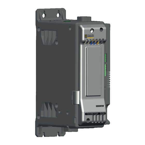
- Page 1 GB - Installation and operation manual THYRITOP 500 SERIES 25 to 250 A Power Controller...
-
Page 3: Table Of Contents
INDICE Preliminary instructions Electrical connections Profile Power connections General description Connections input/output 25-120A Preliminary instructions Connections input/output THYRITOP 500 150-250A Functions of indicator leds Installation and Connection Control connectors Electrical power supply Configuration TTL port Notes on electrical safety (THYRITOP 500 standard) and electromagnetic compatibility Serial comunication port Modbus RS485 (option) Recommendations for correct installation... -
Page 4: Preliminary Instructions
Power control with Soft start ramp limits load, optimizes rofile the consumptions and increases the load operating duration. The THYRITOP 500 series of microprocessor advanced solid Device parameters can be configured from PC, by means of state power units controls, in compact and optimized size, high... -
Page 5: Preliminary Instructions
See paragraph 2.1 “ Dimensions and mounting” before installing reliminary instruction the THYRITOP 500 on the machine/host system control panel. For configuration via PC, use the PYROTOOLS software and its Read the following preliminary instructions before connection cable. installing and using the THYRITOP 500 modular For the order code, see Section: “Technical-Commercial Information ”... -
Page 6: Installation And Connection
2 • INSTALLATION AND CONNECTION ecommenDations for orrect nstallation This section contains the instructions needed for emc: for PurPoses of correct installation of THYRITOP 500 controllers on the machine/host system control panel and for 2.3.1 Instrument power supply correct connection of the power supply, inputs, •... - Page 7 • Vertical distance between a device and the panel wall • Obligation d’installation (distance entre les produits pour >100mm garantir la dissipation en condition de convection naturelle) • Horizontal distance between a device and the panel wall at • Tension maxi de ligne du thyristor et limites en transitoire, le last 20mm relais statique est équipé...
- Page 8 906120686_THYRITOP 500_04-2019...
-
Page 9: Dimensions
DIAGRAMME D’ISOLATION imensions Fastening may be done on DIN guide (EN50022) or with (5MA). See figures 1 and 2. All dimensions are expressed in mm. Figure 1 THYRITOP 500 I 50 A THYRITOP 500 I 75 A (Without Fan) THYRITOP 500 I 150 A (Without Fan) Modèle 25 A THYRITOP 500 I 90 A (Without Fan) -
Page 10: Installation
nstallation Attention: respect the minimum distances shown in figure 3 to provide adequate air circulation. Figure 3 For correct attachment/release of the module on the DIN guide, do as follows: : - keep the attach/release cursor pressed - insert/remove the module - release the cursor Figure 4 Figure 5... -
Page 11: General Description Thyritop 500 25-120A
tHyritoP 500 i 25-120 a escriPtion Figure 7 THYRITOP 500 Standard THYRITOP 500 with option sérieRS485 1. Supply/control connnector 2. HB key calibration 3. TTL port for configuration 4. LED indicators 5. Power terminal “Line” (1/L1) 6. Power terminal “Load” (2/T1) 7. -
Page 12: Cleaning/Checking Or Replacing The Fan
THYRITOP 500 I 150-250 A leaninG HeckinG or rePlacinG tHe fan Figure 9 1. Fan 2. Lower grille (ventilation intake) 3. Detail of insertion of fan connector in PCB PERIODIC CLEANING Every 6-12 months (depending on the dust level of the installation) blow a compressed air jet downward through the upper rectangular cooling grilles (on the side opposite the fan). - Page 13 tHyritoP 500 i 150-250a) ePlacinG tHe nternal Ptional only for ATTENTION Before and during the inspection/maintenance cut power to the fuse controller and verify that the system is isolated for operator safety Undo the cover fastening screw (1) Remove the cover following the movement indicated by the arrow (2) In this way the fuse is discovered (3) Unscrew the two nuts fastening the fuse using an N.13 wrench (THYRITOP 500 I 150 A) or a size-17 wrench (THYRITOP 500 I 200-250 A)
-
Page 14: Electrical Connections
3 • ELECTRICAL CONNECTIONS ower connections CABLE SECTIONS Table 4 TIGHTENING TORQUE / CURRENT TERMINAL CABLE WIRE WIRE TERMINAL LEVEL TOOL 4 mm² Wire terminal / Eye 2.5 Nm / Phillips screwdriver 1/L1, 2/T1, PE 10 AWG D. 6mm PH2 - PH3 10 mm²... - Page 15 tHyritoP 500 i 25-120 a i nPut utPut onnections Figure 11 Top view Top view WITHOUT Modbus RS485 WITH Modbus RS485 Key HB Key HB Address x 1 J3, J4 Address x 10 RJ10 connectors Switch for serial line serial line TTL port for RS485 Modbus PC configuration...
- Page 16 THYRITOP 500 I 150-250A i nPut utPut onnections Figure 12 Protection du Protection Fan ventilateur Line voltage connector Connecteur tension de ligne Connection “line” connection de la LIGNE” Borne de tension Connection Line voltage terminal “line” connection de ligne de la LIGNE Vis du capot supérieur: Screw front cover (vue du fusible)
- Page 17 unctions of inDicator leDs Description of LEDs able 5 DESCRIPTION COLOR Flashing : during normal operation green Fixed On : depending on FW programming (see Software Manual) Off : during normal operation STATUS yellow On : depending on FW programming (see Software Manual) ALARM State HB alarm output / Power Fault Alarm / Fuse Open State digital input...
- Page 18 Connector J1 THYRITOP 500 I 150-250 A OUTPUTS 3.5.2 Figure 15 Tableau 8 CONNECTOR J1 THYRITOP 500 I 150-250 A 0,2 - 2,5mm 24-14AWG 0,25 - 2,5mm 23-14AWG Figure 16 Connection schema J1 THYRITOP 500 I 150-250 A CONNECTOR J1, J4 THYRITOP 500 I 150-250 A Tableau 9 DESCRIPTION OUT AL HB...
- Page 19 Connector J3 THYRITOP 500 I 150-250 A 3.5.4 Digital inputs Figure 19 Tableau 12 CONNECTOR J3 THYRITOP 500 I 150-250 A (DIGITAL INPUT) 0,2 - 2,5mm 24-14AWG 0,25 - 2,5mm 23-14AWG Figure 20 Connection schema J3 for THYRITOP 500 I 150-250 A CONNECTOR J3 THYRITOP 500 I 150-250 A (DIGITAL INPUT) Tableau 13...
- Page 20 (THYRITOP 500 Standard) onfiGuration Port Connector THYRITOP 500 I 25-120 A - Connector J5 THYRITOP 500 I 150-250 A Connector S1/S2 Nr. Pin Name Description Note RJ10 4-4 pin Ground RX_TTL Data reception TTL from TH 500 TX_TTL Data transmission TTL to TH 500 You are advised only to use this port for configuration of the parameters (Reserved...
- Page 21 onnection examPle ower section Connection example THYRITOP 500 I 25-120 A for one single-phase load, single-phase line (L1-N) or open delta (L1-L2) Figure 24 Connection example THYRITOP 500 I 150 A -250 A for 1 single-phase load, single-phase line L1-L2/N Figure 25 CONTROLLER 906121686_THYRITOP 500_04-2019...
- Page 22 Connection example THYRITOP 500 I 25-120A for one single-phase load with transformer single-phase line (L1-N) or open delta (L1-L2) Figure 26 Connection example THYRITOP 500 I 150 A -250 A for 1 single-phase load with transformer single-phase line L1-L2/N. Figure 27 906121686_THYRITOP 500_04-2019...
- Page 23 Connection example 2-phase (Master-Slave) THYRITOP 500 I 25-120A for one load 3-phase. Figure 28 Connection example 2-phase (Master-Slave) THYRITOP 500 I 150-250A for one load 3-phase. Figure 29 906121686_THYRITOP 500_04-2019...
- Page 24 Connection example 3-phase (Master-Slave with control on 3 lines) THYRITOP 500 I 25-120A for one load 3-phase. Figure 30 Connection example THYRITOP 500 I 25-120A three-phase (3 master units) for single-phase loads, with division of maximum load with isolators S1, S2, S3, maintaining balance of three-phase line. Figure 30b 906121686_THYRITOP 500_04-2019...
- Page 25 Connection example 3-phase THYRITOP 500 I 150-250A (Master-Slave control on 3 lines) for one load 3-phase. Figure 31 Connection example 2-phase THYRITOP 500 I 25-120A (Master) with THYRITOP 200-1P (slave) for one load 3-phase. Figure 32 906121686_THYRITOP 500_04-2019...
- Page 26 Connection example THYRITOP 500 I 25-120A (with N. 3 THYRITOP 500) for 3-phase star load with neutral. Figure 33 Connection example THYRITOP 500 I 150-250A (with N. 3 THYRITOP 500)for 3-phase star load with neutral. Figure 34 906121686_THYRITOP 500_04-2019...
- Page 27 Connection example THYRITOP 500 I 25-120A (Master with 2 Slave THYRITOP 200-1P) for 3-phase star load with neutral. Figure 35 Connection example THYRITOP 500 I 25-120A (3 Master) for 3-phase star load with neutral. Figure 36 HB OUT ALARM SWITCH Analog Output 0-10 V 0-5 V...
- Page 28 Connection example THYRITOP 500 I 25-120A (3 Master) for a three-phase open delta load. Figure 37 HB OUT ALARM SWITCH Analog Output 0-10 V 0-5 V POTENTIOMETER 1 2 3 4 5 6 7 8 9 1 2 3 4 5 6 7 8 9 1 2 3 4 5 6 7 8 9 24 Vdc/ac SUPPLY...
- Page 29 NOTES USE WITH INDUCTIVE LOADS AND TRANSFORMERS Connect a varistor (MOV) between each wire of the primary transformer and ground. Varistor data: rated voltage 660Vrms,…, 1000Vrms; minimum energy 100J The maximum current controllable by the device is less than the product’s rated value (see technical data). In ZC and BF trigger mode, use the Delay-triggering function to limit peak magnetization current.
- Page 30 variable cycle time (GTT). This mode controls power on the load via a series of conduction ON and non conduction OFF cycles. The ratio of the number of ON cycles to OFF cycles is proportional to the power value to be supplied to the load. The CT repeat period is kept to a minimum for each power value (whereas in ZC mode the period is always fixed and not optimized) A parameter bF.Cy defines the minimum number of conduction cycles settable from 1 to 10.
- Page 31 Phase angle (PA) This mode controls power on the load via modulation of trigger angle , Example: if power to be transferred to the load is 100%, q = 180° or if power to be transferred to the load is 50%, q = 90° Figure 41 Resistive load Inductive load...
- Page 32 RMS current limit The option for controlling the load current limit is available in all work modes. If the current value exceeds the limit (settable in the nominal full-scale range) in mode PA the conduction angle is limited, while in zero-crossing mode (ZC, BF, HSC) the cycle time conduction percentage is limited.
- Page 33 To conduct inductive loads controlled in PA mode, do not use delay triggering; instead, use the phase Soft-Start ramp. Figure 45 Example of phase ramp to fire Example of firing with Delay-Triggering a transformer in PA mode of a transformer in ZC mode Comparaison of method to fire a transformer : Soft-Start Ramp (for PA mode) / Delay triggering (for ZC and BF mode) 906121686_THYRITOP 500_04-2019...
- Page 34 3.10 (Pwm) iGital nPut This digital input can be used to receive information on the % of power to be supplied to the load. The signal can be generated by a controller or external plc via digital outputs (logic output for CA PYROCONTROLE instrumentation).
- Page 35 4 • INSTALLATION OF THE SERIAL PORT A network typically has a Master that “manages” communication by means of “commands,” and Slaves that carry out these commands. THYRITOP 500 modules are considered Slaves to the network master, which is usually a supervision terminal or a PLC.
- Page 36 AUTOBAUD equence Function Adapt the serial communication speed and parity of the THYRITOP 500 modules to the connected supervision INSTALLATION OF terminal or PLC. SERIAL NETWORK 1 ModBus The “RUN”and “STATUS” LEDs mentioned in the procedure can vary its behavior based on on he parameters Ld.1 e Ld.2 The serial network Procedure...
- Page 37 5 • GENERAL CHARACTERISTICS INPUTS IN1 Analogic control inputs Function Acquisition of control power Max. error 1% f.s.+/- 1 scale point at ambient temperature of 25°C Thermal drift < 100 ppm/°C of Sampling time 60 ms Scale 0 -10V Input impedance > 40 Kohms Scale 0-5V Input impedance >...
- Page 38 POWER (SOLID-STATE) CATEGORY OF USE AC 51 resistive or low inductance loads (TAB. 2 EN60947-4-3) AC 55b infrared lamps AC 56a: transformer Trigger mode PA - Load management by adjusting the firing angle (only configuration single-phase or delta open) ZC - Zero Crossing with constant cycle time (settable in range 1-200sec) BF - Burst Firing with variable cycle time (GTT) optimized minimum.
- Page 39 GENERAL DATA Load type and connection Single phase load Independent single-phase load in open delta 3-phase load 3-phase load (star without neutral or closed triangle) with bi-phase control Protection IP20 Work/storage temperature 0…40°C (refer to dissipation curves) / -20 °C - +70 °C average temperature over a period of 12:0 am not exceeding 35°...
- Page 40 6 • TECHNICAL / COMMERCIAL INFORMATION This chapter contains information concerning you immediately identify the hardware configuration of the the control symbols of the controller device. and its main accessories. This is why it is necessary to indicate the control code every time you contact the CA PYROCONTROLE After-Sales As indicated in the preliminary warnings in this User’s Guide, Department to solve any problems.
- Page 41 ccessories CONFIGURATION KIT Kit for PC via the USB port (Windows environment) for THYRITOP 500 standard configuration (TTL port) for configuration of THYRITOP 500 with the RS485 option KIT PC USB / RS485 or TTL Lets you read or write all of the parameters of a single THYRITOP 500 A single software for all models.
- Page 42 NOTES 906121686_THYRITOP 500_04-2019...
- Page 43 COPYRIGHT This manual and the information in it are proprietary data of CA Pyrocontrole. It is prohibited to reproduce or copy these data without express consent in writing from CA Pyrocontrole. Any unauthorized use of this manual and its content is strictly forbidden. Copyright ©...
- Page 44 Conformity TC N° RUД-IT.AЛ32.b.01762 Conformity TC N° RUД-IT.AЛ32.b.01762 FM approvals project NO: 0003054712 EMC: Complies with Directive 2014/30/EU with reference to the EN 61326-1 standard Emission in industrial environments: class A - LVD safety: Complies with Directive 2014/35/EU with reference FM approvals project NO: 0003054712 Conformity C/UL/US File no.