
Related Manuals for TEXIO DL-1060


Summary of Contents for TEXIO DL-1060
- Page 1 INSTRUCTION MANUAL 6 1/2 DIGITAL MULTIMETER DL-1060 DL-1060G/ DL-1060VG DL-1060R/ DL-1060VR B71-0180-31...
-
Page 2: Table Of Contents
NFOMATION 1.1.1 Feature Overview ··································································································· 1 1.1.2 Inspection ············································································································· 2 1.1.3 Taking off the black rubber ring ·················································································· 2 1.1.4 The DL-1060’s Dimension ························································································ 3 1.1.5 Update of the user's manual ······················································································ 3 1.2 S DL-1060 ····································································································· 4 ETTING UP 1.2.1 To adjust the handle ································································································... - Page 3 3.4 S ······················································································· 76 YSTEM ELATED PERATIONS 3.4.1 Display ··············································································································· 76 3.4.2 Beeper ··············································································································· 77 3.4.3 Reading Memory (Store & Recall) ············································································ 79 3.4.4 Sensitivity Band (Hold) ··························································································· 80 3.4.5 Initial Mode·········································································································· 82 3.4.6 Language············································································································ 83 3.4.7 Error Condition ····································································································· 83 3.4.8 Firmware Revision ································································································...
-
Page 4: Using The Product Safely
USING THE PRODUCT SAFELY ■ Preface Before using this product, understand how To use the product safely, read this instruction manual to the end. to correctly use it. If you read the manuals but you do not understand how to use it, ask us or your local dealer. - Page 5 USING THE PRODUCT SAFELY WARNING CAUTION ■ Do not remove the product's covers and panels Never remove the product's covers and panels for any purpose. Otherwise, the user's electric shock or fire may be incurred. ■ Warning on using the product Warning items given below are to avoid danger to user's body and life and avoid the damage or deterioration of the product.
- Page 6 USING THE PRODUCT SAFELY ■ Do not let foreign matter in Do not insert metal and inflammable materials into the product from its vent and spill water on it. Otherwise, electric shock or fire may occur. ■ Warning item on abnormality while in use If smoke or fire is generated from the product while in use, stop using the product, turn off the switch, and remove the power cord plug from the outlet.
-
Page 7: Overview
Overview This chapter will give you an overview of DL-1060’s features and guide you through the basics of DL-1060 digital multimeter 1.1 General Infomation This section contains general information about DL-1060 Multimeter. 1.1.1 Feature Overview DL-1060 series is a 6 1/2 digits multimeter. It has…... -
Page 8: Inspection
Standard Test Leads[1] ⚫ One CD (including this electronic User's Manual and software applications). ⚫ [1] DL-1060 series is provided with a Standard Test Lead set, descryibed below. Test Lead Ratings: Material: IEC 61010-031 CAT III Probe Body: Outer Insulation-Santoprene Rubber. -
Page 9: The Dl-1060'S Dimension
1.1.4 The DL-1060’s Dimension Please get the dimension’s information in the following different ways. 1. The dimension without the handle and the front & Rear Bumpers is in the following Figure 1-1. (L x W x D - 214.6 x 88.6 x 280.7 mm) 2. -
Page 10: Setting Up Dl-1060
1.2 Setting up DL-1060 The purpose of this section is to prepare you for using DL-1060 DMM. You may want to check if you have all the parts with your multimeter. All our products are handled and inspected professionally before shipping out to our customers. If you find any damaged or missing parts, please contact your local service representative immediately and do not attempt to operate the damaged product. - Page 11 Ⅱ. Adjusting the position for your convenience Here are some example positions to for your reference. 【Position 1】 The default position is for packing as shown in Figure 1-6. Figure 1-6 【Position 2】 The position shown in Figure 1-7 is for operating the multimeter. Figure 1-7 【Position 3】...
-
Page 12: To Connect The Power
W ARNING cause severe damage to your instrument. The power cord supplied with DL-1060 contains a separate ground wire for use with grounded outlets. When proper connections are made, instrument chassis is connected to power line ground through the ground wire in the power cord. - Page 13 【Step 2】 Press the latch to unlatch the voltage setting selector container as shown in Figure 1-10. (You may need a screwdriver to do so.) Figure 1-10 【Step 3】 Remove the voltage setting selector container as shown in Figure 1-11. (You may need a screwdriver to do so.) Figure 1-11...
- Page 14 【Step 4】 Open the clips on the sides and remove the voltage setting selector from the container as shown in Figure 1-12. Figure 1-12 【Step 5】 Turn the voltage setting selector so that the desired voltage setting appears in the container as shown in Figure 1-13.
-
Page 15: To Change The Power-Line Fuse
1.2.2.2 To change the power-line fuse Before replacing the power-line fuse, make sure the multimeter is disconnected from the AC power. You must be qualified personnel to perform this action. For continued protection against fire or instrument damage, only replace with fuse of the same type and rating noted on the rear W ARNING panel. - Page 16 【Step 2】 Press the latch to unlatch the voltage setting selector container as shown in Figure 1-15. (You may need a screwdriver to do so.) Figure 1-15 【Step 3】 Remove the voltage setting selector container as shown in Figure 1-16. (You may need a screwdriver to do so.) Figure 1-16 【Step 4】...
- Page 17 【Step 5】 Replace with the new standard fuse. 【Step 6】 Insert the voltage setting selector container back into the. 【Step 7】 Make sure the power switch on the front panel is in “Power OFF” condition before plugging as shown in Figure 1-18. Power Switch Condition FREQ...
- Page 18 【Step 9】 Press on the power switch on the front panel for activating DL-1060 as shown in Figure 1-20. Power Switch Condition FREQ CONT TEMP ENTER NULL SHIFT STORE DIGITS CONFIG TRIGGE R Figure 1-20...
-
Page 19: To Change The Current Input Fuse
1.2.2.3 To change the current input fuse The current input terminals are protected respectively by the fuses(3A,250V Fast Acting, HBC:Our part number F50-0268-08 or 15A,250V Fast Acting, HBC:Our part number F50-0269-08) at front panel. Before replacing the current input fuse, make sure the multimeter is disconnected from the AC power. - Page 20 【Step 2】 Push the current input terminal and turn it right as shown in Figure 1-22. Figure 1-22 【Step 3】 Pull out the terminal (fuse holder) gently and you will find the current input fuse as shown in Figure 1-23. Figure 1-23...
- Page 21 【Step 4】 Remove the broken fuse and replace a new one with the same type or same rating as shown in Figure 2-19. Fuse Current Fuse Holder Figure 1-24 【Step 5】 Insert the fuse holder back and turn it left as shown in Figure 1-25. Make sure the fuse holder is properly seated and secured.
-
Page 22: Factory Default When Power-On
1.2.3 Factory Default When Power-ON Table 1-1 shows the factory default of DL-1060. Table 1-1 Function Default Location after Power On Autozero Frequency and Period Source AC Voltage Output Format ASCII Ratio AC Bandwidth 20Hz AC Voltage AC Digits 5 1/2... -
Page 23: Dl-1060 Function Introduction
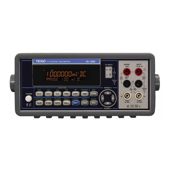
1.3 DL-1060 Function Introduction For users to become familiar with the DL-1060 DMM, we will give a brief introduction to the basic operations of DL-1060 DMM. There are three major parts of DL-1060: (1.3.1) the front panel, (1.3.2) the display, and (1.3.3) the rear panel. We will discuss each of them in the following sections. - Page 24 : Selects diode testing. ⚫ ⚫ TCOUPL: Selects thermocouple temperature measurement. ⚫ 2ND: Setting Secondary measurement. 2-3. Second row without SHIFT button: ⚫ TRIGGER: Manually triggers the multimeter to make measurements or sets the multimeter to take external triggers. ⚫ STORE: Stores a specified number of subsequent readings. ⚫...
-
Page 25: The Display
1.3.2 The Display DL-1060 has a dual-LCD-display for a better view. There are two rows in the dual-display screen. The upper row (Primary) displays readings and units. A maximum 11 characters are allowed for upper row LCD display. The lower row (Secondary) displays range of the measurements, condition, the secondary readings &... -
Page 26: The Rear Panel
1.3.3 The Rear Panel The rear panel of the DL-1060 is shown in Figure 2-20. This figure includes important abbreviated information that should be reviewed before using the instrument. 1 2 3 Fgure 1-28 1. VM COMP: Voltmeter Complete Output Terminal. Outputs a low-true pulse from a remote interface. -
Page 27: Basic Measurement Function
2.1 Voltage Measurements (DCV & ACV) The ranges for DC voltage measurements in DL-1060 are 100mV, 1V, 10V, 100V and 1000V. For AC voltage measurements, the ranges are 100mV to 750V AC-Coupled , or 1000V peak. Figures 2-1 shows the locations of the buttons needed and T-RMS message display for voltage measurement. -
Page 28: Ratio Measurements (Dc Voltage Only)
Figure 2-1 2.2 Ratio Measurements (DC Voltage only) This function calculates the ratio of an input DC voltage to a reference DC voltage according to the following equation: ※ Note: This function only applies to DC voltage measurement. How to make a ratio measurement There are two ways to make a ratio measurement: Through the front panel operation or through the remote interface operation. - Page 29 Figure 2-2 Remote Interface Operation Use the following command to make a RATIO measurement. CONFigure:VOLTage:DC:RATio {<range>|MIN|MAX|DEF},{<resolution>|MIN|MAX|DEF}...
-
Page 30: Current Measurements (Dc & Ac)
2.3 Current Measurements (DC & AC) The ranges for DC current measurements in DL-1060 are 10mA, 100mA, 1A, 3A and 10A. For AC current measurements, the range is 1A with a sensitivity of 1 μA to 10A AC-Coupled T-RMS with a sensitivity of 10 μA. Figure 2-3 shows you how to measure DC/AC currents in DL-1060. -
Page 31: Resistance Measurements (2 & 4-Wire)
2.4 Resistance Measurements (2 & 4-wire) The ranges for resistance measurement are 100 Ω, 1KΩ, 10kΩ, 100kΩ, 1MΩ, 10MΩ, and 100MΩ, with a sensitivity of 100 μΩ (at 100 Ω range.) There are two modes for measuring the resistance: 2-wire mode as shown in Figure 2-4 and 4-wire mode as shown in Figure 2-5. -
Page 32: Frequency & Period Measurements
2.5 Frequency & Period Measurements DL-1060 uses an on-board counter with 25MHz to measure the frequency / period. The measurement band is from 3Hz to 300kHz (or 333 ms to 3.3 μs) and the measurement voltages range from 100mV to 750 V in AC. The range default setting is auto-range. - Page 33 How to measure period 1. Connect the test leads to the terminals on the front panel as shown in Figure 2-7. 2. Set RESOLUTION (refer to 3.1.3 Resolution & NPLC Setting) or skip this step to use the default setting. 3.
-
Page 34: Continuity Measurements
2.6 Continuity Measurements DL-1060 uses 1kΩ range for the continuity measurement. The meter beeps when the test resistance is less than the threshold resistance. The default threshold resistance is 10Ω, but user can set the threshold resistance to anything between 1Ω and 1kΩ. -
Page 35: Diode Measurements
2.7 Diode Measurements DL-1060 uses a current source of 1 mA for diode testing. The maximum resolution is 10 μV on a fixed range of 1 V DC. The default threshold voltage is fixed between 0.3 and 0.8 volts and the reading rate is fixed at 0.1 PLC (The voltage bound is adjustable from 0.01V up to 1.2V.). -
Page 36: Temperature Measurements
DL-1060 supports thermocouples and resistance temperature detector (RTD) types of probes. For thermocouples, DL-1060 supports 9 types: E, J, K, N, R, S, B, T, and C. Please refer to Table 2-1 for their temperature ranges. Be sure that the temperature function is configured for the right sensor type before making measurements (Refer to 3.1.8 Sensor Selection for how to make the sensor configuration). -
Page 37: Thermocouple Measurements
2.8.1 Thermocouple Measurements Connect the thermocouple to the TC INPUT jack on the front panel. The difference between each type is subject to sensors. How to measure thermocouple 1. To measure thermocouple must be via a purposive sensor as shown in Figure 2-9. -
Page 38: 2-Wire Rtd Measurements
2.8.2.1 2-Wire RTD Measurements How to measure temperature with 2-Wire RTD The following Figure 2-10 shows theory diagram of 2-Wire RTD measurement. 1. Insert a specified adapter into the front terminals. 2. Press TEMP button. 3. Configure sensor type and unit by using the CONFIG button (refer to 3.1.8 Sensor Selection) or skip this step to use the default settings. -
Page 39: 4-Wire Rtd Measurements
Figure 2-11 2.8.2.3 4-Wire RTD Measurements How to measure temperature with 4-Wire RTD The following Figure 2-12 shows theory diagram of 4-Wire RTD measurement. 1. Insert a specified adapter into the front terminals. 2. Press TEMP button. 3. Configure sensor type and unit by using the CONFIG button (refer to 3.1.8 Sensor Selection) or skip this step to use the default settings. -
Page 40: Capacitance Measurements
2.9 Capacitance Measurements The ranges for capacitance measurements in DL-1060 is 1 nF, 10 nF, 100 nF, 1 μF, 10μF, 100μF, 1000μF and 10000μF. The default for “range” is auto-range. How to measure capacitance Connect the test leads to the terminals on the front panel as shown in Figure 2-13. -
Page 41: 2Nd Measurement
2.10 2ND Measurement DL-1060 provides a secondary measurement function as users make a primary measurement. By using 2nd function, users are able to make two measurements at the same time. The Table 2-2 below shows the available measurement functions for each primary measurement on DL-1060. - Page 42 How to use 2ND measurement 1. Press one of the measurement function keys to select a primary measurement. 2. Press SHIFT+ENTER to enter 2ND submenu. 3. Use ◁ or ▷ button to locate a desired secondary measurement, and press ENTER to select it.
- Page 43 [SENSe:]FUNCtion “<function>” For example: FUNCtion[1/2] “VOLTage:DC” FUNCtion[1/2] “VOLTage:AC” FUNCtion[1/2] ”CURRent:DC” FUNCtion[1/2] “CURRent:AC” FUNCtion[1/2] “FREQunecy” FUNCtion[1/2] “PERiod” FUNCtion[1/2] “FREQunecy:CURR” FUNCtion[1/2] “PERiod:CURR” FUNCtion[1/2] “RESistance” FUNCtion[1/2] “FRESistance” FUNCtion[1/2] “CAPacitance” FUNCtion[1/2] “TEMPerature” FUNCtion[1/2] “TCOuple” FUNCtion[1/2] “NONE” FUNCtion[1/2]? When enabling the 2nd function, you can still set the range and NPLC individually. The setting procedures are as usual.
-
Page 44: Front Panel Operations
The purpose of Auto Zero function is to minimize the offset influence on your measurements. When Auto Zero is enabled, DL-1060 takes the input signal reading as a base value and then internally disconnects the input signal, and takes a offset reading (a null offset). - Page 45 How to set Auto Zero The following steps show how to set Auto Zero directly through the front panel. Be aware that Auto Zero setting is always affected by the resolution setting. Whenever the resolution is altered, Auto Zero may be changed accordingly. The relation between resolution and Auto Zero is shown in Table 3-1.
-
Page 46: Filter
3.1.2 Filter Filter is used to remove noises in measurement readings. DL-1060 is equipped with two types of filters: AC filter and digital filter. AC filter is for AC measurements only. It also affects the speed of the multimeter to yield a measurement reading. Digital filter further stabilizes the measurement readings by averaging. -
Page 47: Digital Filter
3.1.2.2 Digital Filter Definition: DL-1060 uses an averaging digital filter to yield a reading for display from a specified number of measurement readings in the past. The past measurement readings are stored in a stack of memory. The number may be in the range of 2 to 100. You may select one of the two modes of digital filter operations: Moving Average and Repeating Average. - Page 48 Default The digital filter is enabled and is in moving average mode with 10 readings by default. Front Panel Operation How to enable/disable digital filter 1. Press SHIFT+DIGITS buttons to switch to the digital filter function as shown in Figure 3-3. 2.
- Page 49 Figure 3-4 For READINGS setting: 1. After enabling the filter (see above), use ◁ and ▷ button s to locate “READINGS”. Press ENTER to select it. Use ◁ and ▷ to move through the digits and △ and ▽ buttons to increase or decrease the number to a desired to a value (from 2 to 100).
-
Page 50: Resolution & Nplc Setting
3.1.3 Resolution & NPLC Setting Definition Resolution is the number of digits a multimeter can measure. You can select the resolution for a specific measurement. The choices for the resolution setting are: 4 1/2, 5 1/2, 6 1/2. For a faster measurement, you can select 0.001 PLC. For a stable, higher accuracy measurement, 100PLC is suggested to select. - Page 51 Figure 3-6 ※ Note: When using the Way One to set the resolution, your options with each press on the same button are 4 1/2, 5 1/2 and 6 1/2. And under tha DCV, DCI, Ω2 & Ω4 functions, the NPLC just can be set by pressing CONFIG > NPLC > ENTER > ◁ and ▷ >...
-
Page 52: Threshold Resistance (Continuity)
3.1.4 Threshold Resistance (Continuity) Definition When testing continuity, the beeper goes off when the measured resistance is less than the threshold resistance. The threshold resistance can be set to any value between 1Ω and 1000Ω. Default The factory default for continuity threshold resistance is 10Ω. Your selection is stored in a volatile memory and the default value will be restored after the meter has been turned off. -
Page 53: Range (Manual & Auto)
Definition When making measurements except CONT, DIODE, TCOUPL, and Temperature, DL-1060 will automatically choose a range for you, or you can select the appropriate range manually. The difference between auto-range and manual-range is the settling time. Auto-range is a convenient way for you, but manual-range can usually speed up the process. -
Page 54: Rate (Integration Time)
The unit of the integration time is in PLC (power line cycles). One PLC for 60 Hz is 16.67 ms, and for 50 Hz is 20 ms. There are 10 different integration times in DL-1060 for user to select from: 0.001, 0.006, 0.02, 0.06, 0.2, 0.6, 1, 2, 10, and 100 PLC. - Page 55 SENSe:CURRent:DC:NPLCycles {0.001|0.006|0.02|0.06|0.2|0.6|1|2|10|100|MINimum|MAXimum} SENSe:CURRent:DC:NPLCycles? [MINimum|MAXimum] SENSe:RESistance:NPLCycles {0.001|0.006|0.02|0.06|0.2|0.6|1|2|10|100|MINimum|MAXimum} SENSe:RESistance:NPLCycles? [MINimum|MAXimum] SENSe:FRESistance:NPLCycles {0.001|0.006|0.02|0.06|0.2|0.6|1|2|10|100|MINimum|MAXimum} SENSe:FRESistance:NPLCycles? [MINimum|MAXimum] For frequency and period measurements, aperture time (or gate time) is analogous to integration time, and you can use the following commands to set it. Specify 10 ms (4 1/2 digits), 100 ms (default;...
-
Page 56: Sensor Selection For Temperature Measurements
3.1.7 Sensor Selection for Temperature Measurements The multimeter supports both thermocouple and RTD. User needs to configure the multimeter right sensor type before they make temperature measurements. Definition If you are using RTD, the options are: PT100, D100, F100, PT385, PT3916, user-defined RTD, NTCT and SPRTD. - Page 57 International Temperature Scale of 1990”. In each subrange, the calibration constants required for that subrange are listed. Default The default sensor type in DL-1060 is PT100. How to set up RTD You can set up the RTD configuration either through the front panel operation or through the remote interface operation as shown in Figure 3-10 or through the remote interface operation.
- Page 58 Choosing USER takes you to a menu where you can specify factors used in the calculation equation to obtain the temperature. Use ◁ and ▷ to move through the digits and △ and ▽ to change the numbers to a desired value. Press ENTER to set the value.
- Page 59 Thermocouple Definition DL-1060 is built-in cold junction compensation that can improve the accuracy of thermo measurements. If you are using this function, you have to set an adapter type. For example, through the “TYPE” selections you are available to use a specific adapter K, J, R, S, T, E, N, B, or C for temperature measurement.
- Page 60 Figure 3-12 Real Temperature Setup 1. Selet a type and matched an adaptor correctly as shown in Figure 3-13. 2. Press SHIFT+ TEMP to choose thermocouple function. 3. Press CONFIG, and then use ◁ and ▷ to locate “REAL”, then press ENTER to check the present temperature.
-
Page 61: Remote Interface Selection
SENSe:TCOuple:SIMulated {<value>|MINimum|MAXimum} 3.1.8 Remote Interface Selection The DL-1060 Series provide USB, GP-IB, and RS-232C interfaces: DL-1060 provides USB interface, and DL-1060G/VG provides both GP-IB and USB interfaces, and DL-1060R/VR provides both RS-232C and USB interfaces, but only one interface can be activated at a time. - Page 62 Figure 3-15 How to set the Address when using GP-IB 1. Press SHIFT + CONFIG buttons, and then use ◁ and ▷ buttons to locate “INTERFACE”. Press ENTER to select it as shown in Figure 3-16. 2. Use ◁ and ▷ buttons to locate “GPIB”. Press ENTER to select it. 3.
- Page 63 3. Use ◁ and ▷ buttons to select the desired option. Press ENTER to set it. BAUD RATE: 300, 600, 1200, 2400, 4800, 9600, 19200, 38400, 57600, or 115200(bps) DATA BITS: 7 BITS or 8 BITS PARITY: NONE, ODD, or EVEN STOP BITS: 1 BIT or 2 BITS FLOW CONTROL: NONE or DTR/DSR Delimiter: LF(fixed)
-
Page 64: Trigger Operations
Following Figure 3-17 describes the detail of the trigger setup. Figure 3-17 The trigger system is supposed to be in an idle status when DL-1060 is not measuring. ( *(sampling)display will illuminates when measurement is in progress ) When starting measurement after idle status, the trigger system should be in trigger waiting status. -
Page 65: Trigger Mode
3.2.1 Trigger Mode There are three trigger modes in DL-1060: auto, immediate, and single triggering. You can specify the trigger mode for your measurement. The factory default is auto triggering when the meter is power-on. A. Auto Triggering Mode (Front Panel Operation only) - Page 66 How to use Immediate Trigger Use the following command in your PC terminal to set the internal immediate trigger. TRIGger:SOURce IMMediate C. Single Trigger Mode (Front panel operation only) Definition Single trigger mode takes one reading (or specified number of readings) each time when user presses TRIGER key.
-
Page 67: Trigger Source
3.2.2 Trigger Source In DL-1060, you can specify the trigger source to be one of these three options: front panel operations, external hardware trigger source and remote interface operations. Front Panel Operation Use SHIFT + TRIGGER buttons for auto triggering and TRIGGER button for single triggering. -
Page 68: Trigger Setting
PC terminal: TRIGger:SOURce IMMediate 3.2.3 Trigger Setting In DL-1060, you can specify a variety of trigger settings including the number of samples per trigger, the number of triggers per event, reading hold, and the trigger delay for your measurements. - Page 69 Front Panel Operation 1. Press SHIFT+CONFIG buttons as shown in Figure 3-20. 2. Set a defined parameter via the procedure TRIG SYS > TRIG CNT > ENTER. 3. Set the desired number by pressing △and ▽ buttons to increase or decrease the number, and using ◁...
- Page 70 Defaults The default of the trigger delay is automatic. DL-1060 automatically selects a delay time for you according to the setting of the measurement if you do not specify a delay. A list of the default for each measurement function is shown on Table 3-4. The range for the delay is from 0 to 3600 seconds.
- Page 71 Table 3-4 Measurement Function Setting Trigger Delay Time PLC >= 1 1.5 ms DCV/DCI PLC < 1 1.0 ms 100Ω to 100kΩ 1.5 ms Ω2 and Ω4 1 MΩ 15 ms (PLC >= 1) 10 MΩ to 100 MΩ 100 ms 100Ω...
-
Page 72: Math Operations
TRIGger:DELay:AUTO {OFF|ON} 3.3 Math Operations This section will introduce the mathematical operations in DL-1060. There are eight math operations: PERCENT, AVERAGE, NULL, LIMITS (HIGH LIMIT/LOW LIMIT), MX+B, dB and dBm testing. They either store data for later use or perform mathematical operations on the readings. -
Page 73: Percent(%)
3.3.1 Percent(%) Definition This mathematical function calculates the ratio of a measurement reading to a specified target value as the form of percentage. The calculation formula is shown below: The specified target value is store in a volatile memory and will be cleared after the meter has been turned off or a remote interface reset. -
Page 74: Average (Avg/Min/Max/Count)
3.3.2 Average (AVG/MIN/MAX/COUNT) Definition When the Average function is enabled, DL-1060 takes in a series of readings from the measurements, stores the minimum and maximum readings in the memory, and then calculates the average value of all readings and reading counts. The number of readings taken since Average operation is enabled is recorded as well. -
Page 75: Null(Relative)
Remote Interface Operation The following commands show you how to use the Average operation from your PC terminal. CALCulate:FUNCtion AVERage CALCulate:STATe {OFF|ON} CALCulate:STATe? CALCulate:AVERage:MINimum? CALCulate:AVERage:MAXimum? CALCulate:AVERage:AVERage? CALCulate:AVERage:COUNt? 3.3.3 Null(Relative) Definition When the null function is enabled, the displayed measurement reading will show something difference between the measured input signal reading and the stored null (also called relative) value. -
Page 76: Limits Test
Figure 3-24 ※Note:Press NULL button again or press other measurement buttons to disable this feature. The “MATH” anunnciator on the display indicates the state of a mathematical operation. The Remote Interface Operation You can use the following commands on your PC terminal to make a null measurement. - Page 77 CALCulate:LIMit:LOWer? [MINimum|MAXimum] CALCulate:LIMit:UPPer {<value>|MINimum|MAXimum} CALCulate:LIMit:UPPer? [MINimum|MAXimum] Acquisition of limit test's result The result for Pass/Fail test may be aquired from the USB connector located at rear panel for DL-1060. Please refer "4.1 Pass/Fail Output From USB Connector " for detail.
-
Page 78: Mx+B
3.3.5 MX+B Definition This mathematical function multiplies a measurement reading (X) by a specified scale factor (M) and add an offset (B) automatically. The answer (Y) will then be shown on the display according to the following equation. Y=MX+B This is especially useful when you need to do slope calculations on a series of measurements. -
Page 79: Db/Dbm
Remote Interface Operation Use the following commands to enable and configure MX+B function: CALCulate:FUNCtion MXB CALCulate:STATe {OFF|ON} CALCulate:STATe? CALCulate:MXB:MMFactor {<value>|MINimum|MAXimum} CALCulate:MXB:MMFactor? [MINimum|MAXimum] CALCulate:MXB:MBFactor {<value>|MINimum|MAXimum} CALCulate:MXB:MBFactor? [MINimum|MAXimum] 3.3.6 dB/dBm A. dB Definition The dB feature takes a DC or AC voltage measurement and displays it in decibel unit in correspondence to a relative reference value. - Page 80 Definition With dBm selected, a voltage measurement is displayed as the level of power, relative to 1 milliwatt, dissipated through a reference resistance. The reference resistance is adjustable in DL-1060. The calculation of dBm is defined as below: ...
- Page 81 How to set the reference resistance User can set the reference resistance either through the front panel operation or the remote interface operation. Front Panel Operation 1. Select a measurement function by pressing DCV or ACV button. 2. Do the procedure SHIFT + NULL > dBm > ENTER > REL RES to access the setting as shown in Figure 3-28.
-
Page 82: System Related
3.4 System Related Operations In DL-1060, each system related operation performs a task that is not measurement related but plays an important role in making your measurements. 3.4.1 Display DL-1060 has a dual-LCD-display screen. A maximum of 11 characters are allowed for upper row primary display and a maximum of 16 characters are allowed for lower row secondary display as shown on Figure 3-29. -
Page 83: Beeper
(clears the message displayed) 3.4.2 Beeper DL-1060 beeps when some certain conditions are met or when an error occurs. But there may be time you want to disable the beeper for some operations. Although you can turn off the beeper, the click sound you hear when a button is pressed will not be disabled. - Page 84 After the beeper is disabled, the meter still emits a tone when: ⚫ An error occurs. ⚫ Any button on the front panel is pressed. ⚫ The threshold value is exceeded in continuity testing. Default The beeper is enabled when it is shipped from the factory. How to control the beeper User can control the beeper from either the front panel operation or the remote interface operation.
-
Page 85: Reading Memory (Store & Recall)
You can store the readings and access to the stored readings through either the front panel operation or the remote interface operation. ※ Note: Each datum stored from DL-1060 to remote interface will be in a first in and first out condition. -
Page 86: Sensitivity Band (Hold)
DATA:POINts? (Use this command to query the number of stored readings.) 3.4.4 Sensitivity Band (Hold) The reading hold function captures and holds a stable reading on the display. DL-1060 beeps and holds the value when it detects a stable reading. The sensitivity band in reading hold decides which reading is stable enough. - Page 87 Default The default band is 0.1%. The defined selection is stored in a volatile memory and it will be cleared after the meter has been turned off. How to enable/disable HOLD feature 1. Press SHIFT + TRIGGER buttons. The HOLD anunciator will light up when HOLD feature is enabled as shown in Figure 3-34.
-
Page 88: Initial Mode
The section contains two selections: “DEFAULT” and “SAVE DATA”. You can select “SAVE DATE” to save the current configuration or select “DEFAULT SET” to restore the factory value after restarting DL-1060. The valid range of “SAVE DATA” is listed in Table 3-5. -
Page 89: Language
3.4.6 Language DL-1060 supports two languages: DEFAULT (DL-1060) and COMPATIBLE(Keysight 34401A). How to set up the language 1. Do the procedure SHIFT + CONFIG > SYSTEM > ENTER > LANGUAGE > ENTER > DEFAULT/COMPATIBLE > ENTER to select the language as shown in Figure 3-37. -
Page 90: Firmware Revision
Figure 3-38. Figure 3-38 3.4.8 Firmware Revision DL-1060 has three microprocessors for various internal systems. You can query the multimeter to determine which revision of firmware is installed for each icroprocessor. How to check the firmware revision 1. Do the procedure SHIFT + CONFIG > SYSTEM > SYSTEM VER > ENTER to check the DL-1060’s firmware version. -
Page 91: Self-Test
3.4.10 Self-test ※ Notice: Do not use “SELF TEST” since it is used only for an after sales service operation. -
Page 92: Remote Interface Operations
Appendix B. for SCPI reference. 4.1 Pass/Fail Output From USB Connector The USB connector on the rear panel of DL-1060 is a type-B connector. When the USB interface is disabled, the internal pass and fail TTL output signals (limit testing) will be transmitted to the USB connector. -
Page 93: Setting U P Forr
Pass/Fail signal output abnormal. 4.2 Setting Up For Remote Interface DL-1060 may be remote controlled through USB, GPIB interface (only G type), or RS-232 interface (only R type). Kind of interface should be selected in order to use remote interface. Please refer to chapter 3.1.8 for detail of selection. Next, following software should be installed into the PC for control. -
Page 94: Remote Interface
4.3 Remote Interface Commands You can instruct the multimeter to take measurements by using the SCPI (Standard Commands for Programmable Instruments) commands after the appropriate setup for their selected remote interface. The following conventions are used in SCPI command syntax. ⚫... - Page 95 VOLTage:AC {<range>|MIN|MAX|DEF},{<resolution>|MIN|MAX|DEF} CURRent:DC {<range>|MIN|MAX|DEF},{<resolution>|MIN|MAX|DEF} CURRent:AC {<range>|MIN|MAX|DEF},{<resolution>|MIN|MAX|DEF} RESistance {<range>|MIN|MAX|DEF},{<resolution>|MIN|MAX|DEF} FRESistance {<range>|MIN|MAX|DEF},{<resolution>|MIN|MAX|DEF} FREQuency {<range>|MIN|MAX|DEF},{<resolution>|MIN|MAX|DEF} PERiod {<range>|MIN|MAX|DEF},{<resolution>|MIN|MAX|DEF} CONTinuity DIODe TCOuple TEMPerature CONFigure? The READ? Command The READ? Command changes the state of the trigger system from the “idle” state to the “wait-for-trigger” state. When the specified trigger condition requirements are met after the multimeter receives the READ? command, the measurement will be initiated.
- Page 96 The SENSe Commands ※ Note: Default parameters are shown in bold italic. [SENSe:] FUNCtion “VOLTage:DC” FUNCtion “VOLTage:DC:RATio” FUNCtion “VOLTage:AC” FUNCtion “CURRent:DC” FUNCtion “CURRent:AC” FUNCtion “RESistance” (2-wire Ω) FUNCtion “FRESistance” (4-wire Ω) FUNCtion “FREQuency” FUNCtion “PERiod” FUNCtion “CONTinuity” FUNCtion “DIODe” FUNCtion “TCOuple” FUNCtion “TEMPerature”...
- Page 97 [SENSe:] VOLTage:DC:RANGe:AUTO {OFF|ON} VOLTage:DC:RANGe:AUTO? VOLTage:AC:RANGe:AUTO {OFF|ON} VOLTage:AC:RANGe:AUTO? CURRent:DC:RANGe:AUTO {OFF|ON} CURRent:DC:RANGeAUTO? CURRent:AC:RANGe:AUTO {OFF|ON} CURRent:AC:RANGe:AUTO? RESistance:RANGe:AUTO {OFF|ON} RESistance:RANGe:AUTO? FRESistance:RANGe:AUTO {OFF|ON} FRESistance:RANGe:AUTO? FREQuency:VOLTage:RANGe:AUTO {OFF|ON} FREQuency:VOLTage:RANGe:AUTO? PERiod:VOLTage:RANGe:AUTO {OFF|ON} PERiod:VOLTage:RANGe:AUTO? [SENSe:] VOLTage:DC:RESolution {<resolution>|MINimum|MAXimum} VOLTage:DC:RESolution? [MINimum|MAXimum] VOLTage:AC:RESolution {<resolution>|MINimum|MAXimum} VOLTage:AC:RESolution? [MINimum|MAXimum] CURRent:DC:RESolution {<resolution>|MINimum|MAXimum} CURRent:DC:RESolution? [MINimum|MAXimum] CURRent:AC:RESolution {<resolution>|MINimum|MAXimum} CURRent:AC:RESolutioin? [MINimum|MAXimum] RESistance:RESolution {<resolution>|MINimum|MAXimum} RESistance:RESolution? [MINimum|MAXimum]...
- Page 98 TEMPerature:RTD:RZERo? [MINimum|MAXimum] TEMPerature:RTD:ALPHa {<value>|MINimum|MAXimum} TEMPerature:RTD:ALPHa? [MINimum|MAXimum] TEMPerature:RTD:BETA {<value>|MINimum|MAXimum} TEMPerature:RTD:BETA? [MINimum|MAXimum] TEMPerature:RTD:DELTa {<value>|MINimum|MAXimum} TEMPerature:RTD:DELTa? [MINimum|MAXimum] TEMPerature:SPRTD:RZERo {<value>|MINimum|MAXimum} TEMPerature:SPRTD:RZERo? [MINimum|MAXimum] TEMPerature:SPRTD:A4 {<value>|MINimum|MAXimum} TEMPerature:SPRTD:A4? [MINimum|MAXimum] TEMPerature:SPRTD:B4 {<value>|MINimum|MAXimum} TEMPerature:SPRTD:B4? [MINimum|MAXimum] TEMPerature:SPRTD:AX {<value>|MINimum|MAXimum} TEMPerature:SPRTD:AX? [MINimum|MAXimum] TEMPerature:SPRTD:BX {<value>|MINimum|MAXimum} TEMPerature:SPRTD:BX? [MINimum|MAXimum] TEMPerature:SPRTD:CX {<value>|MINimum|MAXimum} TEMPerature:SPRTD:CX? [MINimum|MAXimum] TEMPerature:SPRTD:DX {<value>|MINimum|MAXimum} TEMPerature:SPRTD:DX? [MINimum|MAXimum] [SENSe:] VOLTage:DC:NPLCycles...
- Page 99 [SENSe:] DETector:BANDwidth {3|20|200|MINimum|MAXimum} DETector:BANDwidth? [MINimum|MAXimum] [SENSe:] AVERage:TCONtrol {MOVing|REPeat} AVERage:TCONtrol? AVERage:COUNt {<value>|MINimum|MAXimum} AVERage:COUNt? [MINimum|MAXimum] AVERage:STATe {OFF|ON} AVERage:STATe? [SENSe:] ZERO:AUTO {OFF|ONCE|ON} ZERO:AUTO? INPut: IMPedance:AUTO {OFF|ON} IMPedance:AUTO? MATH OPERATION Commands There are seven math operations. Only one of them can be enabled at a time. They either store data for later use or perform mathematical operations on the readings.
- Page 100 CALCulate: NULL:OFFSet {<value>|MINimum|MAXimum} NULL:OFFSet? [MINimum|MAXimum] CALCulate: LIMit:LOWer {<value>|MINimum|MAXimum} LIMit:LOWer? [MINimum|MAXimum] LIMit:UPPer {<value>|MINimum|MAXimum} LIMit:UPPer? [MINimum|MAXimum] CALCulate: MXB:MMFactor {<value>|MINimum|MAXimum} MXB:MMFactor? [MINimum|MAXimum] MXB:MBFactor {<value>|MINimum|MAXimum} MXB:MBFactor? [MINimum|MAXimum] CALCulate: DB:REFerence {<value>|MINimum|MAXimum} DB:REFerence? [MINimum|MAXimum] CALCulate: DBM:REFerence {<value>|MINimum|MAXimum} DBM:REFerence? [MINimum|MAXimum] DATA:FEED RDG_STORE,{“CALCulate”|””} DATA:FEED?
- Page 101 TRIGGERING DL-1060 provides a variety of trigger operations. You can select a trigger mode, a trigger source and different trigger settings for a specific measurement. Refer to Figure 3-17 for triggering system flow chart. Triggering from a remote interface is a multi-step sequence.
- Page 102 SYSTEM-RELATED Commands Each system related operation performs a task that is not measurement related but plays an important role in making your measurements. FETCh? READ? DISPlay {OFF|ON} DISPlay? DISPlay: TEXT <quoted string> TEXT? TEXT:CLEar SYSTem: BEEPer BEEPer:STATe {OFF|ON} BEEPer:STATe? SYSTem:ERRor? SYSTem:VERSion? DATA:POINts? SYSTEM:IDNSTR “MANUFACTURER,PRODUCT”...
- Page 103 *ESR? *OPC *OPC? *PSC {0|1} *PSC? *SRE <enable value> *SRE? *STB? Other Interface Commands SYSTem:LOCal SYSTem:REMote GP-IB (IEEE-488.2) COMMON Commands *CLS *ESE <enable value> *ESE? *ESR? *IDN? *OPC *OPC? *PSC {0|1} *PSC? *RST *SRE <enable value> *SRE? *STB? *TRG...
-
Page 104: Error Message
When user has read all errors from the queue, the ERROR annunciator turns off. DL-1060 beeps once each time an error occurs. Should more than 20 errors have existed, the last error stored in the queue (the most recent error) is replaced with -350, “Too many errors”. - Page 105 ⚫ -112 Program mnemonic too long A command header with too many characters was received. ⚫ -113 Undefined header An invalid command was received. ⚫ -121 Invalid character in number An invalid character was found in the number specified for a parameter value. ⚫...
- Page 106 ⚫ -221 Settings conflict This error can be generated in one of the following situations: Situation 1: You sent a CONFigure or MEASure command with autorange enabled and with a fixed resolution. Situation 2: You turned math on and then changed to a math operation that was not valid with the present measurement function.
- Page 107 ⚫ 522 Output buffer overflow ⚫ 531 Insufficient memory There is not enough memory to store the requested number of readings in internal memory using the INITiate command. The product of the sample count (SAMPle:COUNt) and the trigger count (TRIGger:COUNt) must not exceed 2000 readings. ⚫...
-
Page 108: Appendix
Appendix A. Specification List DC Characteristics Accuracy ± (% of reading + % of range) [1] Range[2] Function Resolution Input resistance 1 Year (23 ± 5 ℃ ℃ 100.0000 mV 0.1 μV 10 MΩ 0.008 + 0.0045 1.000000 V 1 μV 10 MΩ... - Page 109 Frequency and Period Characteristics Accuracy ± (% of reading) [1] Function Range[2] Frequency (Hz) 1 Year (23 ± 5 ℃ ℃ 100 mV Frequency 10 to 40 0.03 & 750 V[4] 40 to 300 k 0.02 Period [1] Specifications are for 2-hour warm-up condition, 6 1/2 digits and they’re relative to calibration standards.
- Page 110 Capacitance Characteristics Accuracy ± (% of reading + % of range) [1] 1 Year (23 ± ℃ Function Range Test Current ℃ 1 nF 10 μA 2.0+0.80 10 nF 10 μA 1.0+0.50 100 nF 100 μA 1.0+0.50 1 μF 100 μA 1.0+0.50 Capacitance[6] 10 μF...
- Page 111 General Specifications Item Limitation & description Power Supply 100V / 120V / 220V(230V) / 240 V ± 10% Power Line Frequency 50/60 Hz ± 10% Power Consumption 25 VA max Operating Temperature 0 ℃ to 50 ℃ Maximum relative humidity 80% Operating Humidity for temperature up to 31 ℃...
-
Page 112: Remote Interface
B. Remote Interface Reference B.1 An Introduction to the SCPI Language SCPI (Standard Commands for Programmable Instruments) is an ASCII-based instrument command language designed for test and measurement instruments. SCPI commands are based on a hierarchical structure, also known as a tree system. In this system, associated commands are grouped together under a common node or root, thus forming subsystems. - Page 113 The command syntax shows most commands (and some parameters) as a mixture of upper- and lower-case letters. The upper-case letters indicate the abbreviated spelling for the command. For shorter program lines, send the abbreviated form. For better program readability, send the long form. For example, in the above syntax statement, VOLT and VOLTAGE are both acceptable forms.
- Page 114 SCPI Command Terminators A command string sent to the multimeter must terminate with a <new line> character. The IEEE-488 EOI (end-or-identify) message is interpreted as a <new line> character and can be used to terminate a command string in place of a <new line> character. A <carriage return> followed by a <new line>...
-
Page 115: Output Data Formats
String Parameters String parameters can contain virtually any set of ASCII characters. A string must begin and end with matching a double quote. You can include the quote delimiter as part of the string by typing it twice without any characters in between. The following command uses a string parameter: DISPlay:TEXT <quoted string>... - Page 116 MEASure:CURRent:DC? {<range>|MIN|MAX|DEF},{<resolution>|MIN|MAX|DEF} Preset and make a dc current measurement with the specified range and resolution. The reading is sent to the output buffer. MEASure:CURRent:AC? {<range>|MIN|MAX|DEF},{<resolution>|MIN|MAX|DEF} Preset and make a AC current measurement with the specified range and resolution. The reading is sent to the output buffer. For AC measurement, resolution is fixed at 6 ½ digits. Therefore the resolution parameter only affects the front panel display.
-
Page 117: The Configure Command
B.4 The CONFigure Command CONFigure:VOLTage:DC {<range>|MIN|MAX|DEF},{<resolution>|MIN|MAX|DEF} Preset and configure the multimeter for DC voltage measurements with the specified range and resolution. This command does not initiate the measurement. CONFigure:VOLTage:DC:RATio {<range>|MIN|MAX|DEF },{<resolution>|MIN|MAX|DEF} Preset and configure the multimeter for DC:DC ratio measurements with the specified range and resolution. -
Page 118: The Measurement Configuration Command
CONFigure:CONTinuity Preset and configure for a continuity measurement. This command does not initiate the measurement. The range and resolution are fixed at 1kΩ and 5½ digits respectively. CONFigure:DIODe Preset and configure for a diode measurement. This command does not initiate the measurement. - Page 119 [SENSE:] FUNCtion[1/2] “VOLTage:DC” [SENSE:] FUNCtion[1/2] “VOLTage:AC” [SENSE:] FUNCtion[1/2] ”CURRent:DC” [SENSE:] FUNCtion[1/2] “CURRent:AC” [SENSE:] FUNCtion[1/2] “FREQunecy” [SENSE:] FUNCtion[1/2] “PERiod” [SENSE:] FUNCtion[1/2] “FREQunecy:CURR” [SENSE:] FUNCtion[1/2] “PERiod:CURR” [SENSE:] FUNCtion[1/2] “RESistance” [SENSE:] FUNCtion[1/2] “FRESistance” [SENSE:] FUNCtion[1/2] “CAPacitance” [SENSE:] FUNCtion[1/2] “TEMPerature” [SENSE:] FUNCtion[1/2] “TCOuple” [SENSE:] FUNCtion[1/2]? (※...
- Page 120 [SENSe:]UNIT? Query units for temperature measurement. [SENSe:]TCOuple:TYPE {B|C|E|J|K|N|R|S|T} Select thermocouple sensor type. [SENSe:]TCOuple:TYPE? Query thermocouple sensor type. [SENSe:]TCOuple:RJUNction:RSELect {REAL|SIMulated } Select a reference junction type, real or simulated. [SENSe:]TCOuple:RJUNction:RSELect? Query the reference junction type, real or simulated. [SENSe:]TCOuple:RJUNction:SIMulated {<value>|MINimum|MAXimum} Set the default temperature of the simulated reference junction. [SENSe:]TCOuple:RJUNction:SIMulated? Query the default temperature of the simulated reference junction.
- Page 121 [SENSe:]TEMPerature:RTD:BETA {<value>|MINimum|MAXimum} Set the beta constant for the user type. [SENSe:]TEMPerature:RTD:BETA? [MINimum|MAXimum] Query the beta constant for the user type. [SENSe:]TEMPerature:RTD:DELTa {<value>|MINimum|MAXimum} Set the delta constant for the user type. [SENSe:]TEMPerature:RTD:DELTa? [MINimum|MAXimum] Query the delta constant for the user type. [SENSe:]TEMPerature:SPRTD:RZERo {<value>|MINimum|MAXimum} Set the sensor R value at 0 degree Celsius.
- Page 122 [SENSe:]TEMPerature:SPRTD:CX? [MINimum|MAXimum] Query the C coefficient. [SENSe:]TEMPerature:SPRTD:DX {<value>|MINimum|MAXimum} Set the D coefficient. [SENSe:]TEMPerature:SPRTD:DX? [MINimum|MAXimum] Query the D coefficient. [SENSe:]TEMPerature:TRANsducer FRTD Set the RTD Measurement to 4-Wire. [SENSe:]TEMPerature:TRANsducer RTD Set the RTD Measurement to 2-Wire. [SENSe:]<function>:NPLCycles {0.001|0.006|0.02|0.06|0.2|0.6|1|2|10|100|MINimum|MAXimum} Set the integration time in number of power line cycles for the selected function. This command is valid only for DCV, DCI, 2-wire ohms and 4-wire ohms.
-
Page 123: The Math Operation Command
[SENSe:]ZERO:AUTO {OFF|ONCE|ON} Disable or enable the auto zero mode. The OFF and ONCE have a similar effect. OFF mode does issue offset measurement until multimeter goes “WAIT-FOR-TRIGGER” state. Parameter ONCE issues an immediate offset measurement. [SENSe:]ZERO:AUTO? Query the auto zero mode. Returns “1” (ON) or “0” (OFF or ONCE). B.6 The Math Operation Command CALCulate:FUNCtion {PERCent|AVERage|NULL|LIMit|MXB|DB|DBM} Select the math function. - Page 124 CALCulate:AVERage:COUNt? Read the number of readings taken since Min/Max has been enabled. The multimeter clears the value when Min/Max is turned on, when the power has been off or a remote interface reset. CALCulate:NULL:OFFSet {<value>|MINimum|MAXimum} Store a null value in the multimeter’s Null Register. You must turn on the math operation before writing to the math register.
-
Page 125: The Triggering Commands
CALCulate:DB:REFerence? [MINimum|MAXimum] Query the dB relative value. CALCulate:DBM:REFerence {<value>|MINimum|MAXimum} Set the dBm reference value. Choose from: 50 ~ 8000 ohms. CALCulate:DBM:REFerence? [MINimum|MAXimium] Query the dBm reference value. DATA:FEED RDG_STORE,{“CALCulate”|””} Selects whether readings taken using the INITiate command are stored in the multimeter’s internal memory (default) or not stored... -
Page 126: The System-Related Commands
TRIGger:DELay {<seconds>|MINimum|MAXimum} Set a trigger delay time in seconds. The delay is the time between the trigger signal and each sample that follows. Specify a delay time from 0 to 3600 seconds. TRIGger:DELay? Query the trigger delay time. TRIGger:DELay:AUTO {OFF|ON} Disable or enable a automatic trigger delay. - Page 127 DISPlay? Query the display setting. Returns “0” (OFF) or “1” (ON). DISPlay:TEXT <quoted string> Show a message on the front panel display. The allowed message can be up to 16 characters in the lower row display; any additional characters will be truncated. DISPlay:TEXT? Query the message sent to the front panel display.
- Page 128 *IDN? Read the multimeter’s identification string (be sure to dimension a string variable with at least 35 characters). Other Interface Commands SYSTem:LOCal Place the multimeter in the local mode. All buttons on the front panel are fully functional. SYSTem:REMote Place the multimeter in the remote mode. All buttons on the front panel, except the LOCAL button, are disabled.
-
Page 129: The Scpi Status Reporting
B.9 The SCPI Status Reporting Status registers provide the status mechanism described in IEEE488.2. And there are three register groups with various equipment conditions recorded by the status system. They are the Status Byte Register, the Standard Event Register and the Questionable Data Register. The Status Byte Register collects and records high-level summary information which is reported in other register groups. - Page 130 About the Status Byte The conditions from other status registers will be reported by the status byte summary register. To clear an event register will clear the according bits in the status byte summary register. And to read all messages in the output buffer, including all pending queries, will clear the message available bit.
- Page 131 The following conditions will clear the summary register. Users execute a *CLS (clear status) command. ⚫ To query the standard event and questionable data registers will clear only the separate ⚫ bits in the summary register. The following conditions will clear the enable register. Users turn on the power, and have set the DMM previously by using the *PSC 1 command.
- Page 132 The following conditions will clear the standard event enable register. Users turn on the power, and have set the DMM previously by using the *PSC 1 command. ⚫ Users execute a *ESE 0 command. ⚫ ※ Note 1: When the DMM is powered on, the standard event enable register won’t be cleared if users have set the DMM previously by using *PSC 0.
-
Page 133: Status Reporting Commands
B.10 Status Reporting Commands SYSTem:ERRor? Query the multimeter’s error queue. Up to 20 errors can be stored in the queue. Errors are retrieved in first-in-first out (FIFO) order. Each error string may contain up to 80 characters. STATus:QUEStionable:ENABle <enable value> Enable bits in the Questionable Data enable register. -
Page 134: Scpi Compliance Information
“request service” bit (bit 6) is not cleared if a serial poll has occurred. B.11 SCPI Compliance Information This section encloses a list of commands that are device-specific to the DL-1060. Although not included in the 1999.0 version of the SCPI standard, these commands are designed with the SCPI format in mind and they follow all of the syntax rules of the standard. -
Page 135: Gp-Ib (Ieee-488) Compliance Information
FREQuency:VOLTage:RANGe:AUTO? PERiod:VOLTage:RANGe {<range>|MINimum|MAXimum} PERiod:VOLTage:RANGe? [MINimum|MAXimum] PERiod:VOLTage:RANGe:AUTO {OFF|ON} PERiod:VOLTage:RANGe:AUTO? ZERO:AUTO? CALCulate: PERCent:TARGet {<value>|MINimum|MAXimum} PERCent:TARGet? [MINimum|MAXimum] AVERage:MINimum? AVERage:MAXimum? AVERage:AVERage? AVERage:COUNt? NULL:OFFSet {<value>|MINimum|MAXimum} NULL:OFFSet? [MINimum|MAXimum] LIMit:LOWer {<value>|MINimum|MAXimum} LIMit:LOWer? [MINimum|MAXimum] LIMit:UPPer {<value>|MINimum|MAXimum} LIMit:UPPer? [MINimum|MAXimum] MXB:MMFactor {<value>|MINimum|MAXimum} MXB:MMFactor? [MINimum|MAXimum] MXB:MBFactor {<value>|MINimum|MAXimum} MXB:MBFactor? [MINimum|MAXimum] DB:REFerence {<value>|MINimum|MAXimum} DB:REFerence? [MINimum|MAXimum] DBM:REFerence {<value>|MINimum|MAXimum} DBM:REFerence? [MINimum|MAXimum]... - Page 136 *OPC *OPC? *PSC {0|1} *PSC? *RST *SRE <enable value> *SRE? *STB? *TRG Using Device Clear to Halt Measurements Device clear is an IEEE-488 low-level bus message which can be used to halt measurements in progress. Different programming languages and IEEE-488 interface cards provide access to this capability through their own unique commands.
-
Page 137: About Application
NI-VISA is trademark of National Instruments Corp. Visual Basic 6 and VBA(Excel) Learn how to create and use TEXIO IOUtils components, controls, data access, and more with the following Visual Basic 6 sample applications. C.1 Using MEASure? for a Single Measurement The following example uses the MEASure? command to make a single ac current measurement. - Page 138 End If Rem send reset command '*RST' -- reset DL-1060 stat = viWrite(sesn, "*RST", 4, ret) If (stat < VI_SUCCESS) Then MsgBox "System command error. (*RST)", vbExclamation, "DL-1060 multimeter device test" stat = viClose(fList) Exit Sub End If Rem send Clear command '*CLS'-- Clear DL-1060 status register stat = viWrite(sesn, "*CLS", 4, ret)
-
Page 139: Using Configure With A Math Operation
' Array index stat = viOpenDefaultRM(dfltRM) If (stat < VI_SUCCESS) Then 'Rem Error initializing VISA ... exiting MsgBox "USB-TMC resource not found.", vbExclamation, "DL-1060 multimeter device test" Exit Sub End If Rem Find all DL-1060 USB-TMC instruments in the system stat = viFindRsrc(dfltRM, "USB[0-9]*::0x098F::0x2062::?*INSTR", fList, nList, desc) - Page 140 If (stat < VI_SUCCESS) Then MsgBox "System command error. (*RST)", vbExclamation, "DL-1060 multimeter device test" stat = viClose(fList) Exit Sub End If Rem send Clear command '*CLS'-- Clear DL-1060 status register stat = viWrite(sesn, "*CLS", 4, ret) If (stat < VI_SUCCESS) Then MsgBox "System command error.
- Page 141 Sleep (3000) ' wait for math processing Rem fetch the measure data stat = viRead(sesn, readin, 128, ret) If (stat < VI_SUCCESS) Then MsgBox "Read in data error.", vbExclamation, "DL-1060 multimeter device test" stat = viClose(fList) Exit Sub End If Rem set to local mode stat = viWrite(sesn, "system:local", 12, ret)
-
Page 142: The Devquery Function
Visual C++ This C++ sample application is a Win32 console application. It illustrates how to use the TEXIO IOUtils command. A Win32 console application is a Win32 application that uses text-based input and output, not a graphical interface. This allows you to quickly create a Win32 application by using simple input and output functions. - Page 143 == NULL || PviSetAttribute_usb == NULL FreeLibrary (hUSBTMCLIB); hUSBTMCLIB = NULL; MessageBox(NULL, "NIVISA for USBTMC library not ready.", "DL-1060 multimeter device test", MB_OK); return; printf("\n ###### Start C++ Example program. ######\n"); printf(" We check the DL-1060 multimeter on USB port and\n");...
- Page 144 PviOpen_usb(m_defaultRM_usbtmc, instrDescriptor, 0, 0, &m_instr_usbtmc); status = PviSetAttribute_usb(m_instr_usbtmc, VI_ATTR_TMO_VALUE, m_Timeout); if (!hUSBTMCLIB) printf("DL-1060 device connect failed.\n"); return; // Write command "*IDN?" and read the DL-1060 identification string len = 64; pStrout = new char[len]; ZeroMemory(pStrout, len); strcpy(pStrout, "*idn?"); status = PviWrite_usb(m_instr_usbtmc, (unsigned char *)pStrout, 6, &nWritten);...
- Page 145 // Set configure Current DC, range 0.1A strcpy(pStrout, "CONF:CURR:DC 1,0.01"); status = PviWrite_usb(m_instr_usbtmc, (unsigned char *)pStrout, 20, &nWritten); Sleep(3000); // Fetch the DL-1060 measure value ( screen value ) // Set Voltage DC measure strcpy(pStrout, "CONF:VOLT:DC 0.1,0.1"); status = PviWrite_usb(m_instr_usbtmc, (unsigned char *)pStrout, 21, &nWritten);...
- Page 146 7F Towa Fudosan Shin Yokohama Bild. 2-18-13, Shin Yokohama, Kohoku-ku,Yokohama, Kanagawa, 222-0033 Japan http://www.texio.co.jp/...
Need help?
Do you have a question about the DL-1060 and is the answer not in the manual?
Questions and answers