
Related Manuals for TEXIO DL-2060


Summary of Contents for TEXIO DL-2060
- Page 1 INSTRUCTION MANUAL 6 1/2 DIGITAL MULTIMETER DL-2060 DL-2060G/DL-2060VG DL-2060R/DL-2060VR B71-0110-41...
-
Page 2: Table Of Contents
1.1.3.3 To change the current input fuse ................9 1.1.4 Factory Default When Power-ON ................14 1.1.5 Update of the user's manual ..................14 .......................... 15 EATURES 1.3 DL-2060 F ..................15 UNCTION NTRODUCTION 1.3.1 The Front Panel ......................15 1.3.2 The Display ........................ - Page 3 B.8 The System-Related Commands ..................123 B.9 Status Reporting Commands ..................124 B.10 SCPI Compliance Information ..................126 B.11 GP-IB (IEEE-488) Compliance Information ..............128 C. T ........................129 IAGRAM D. DL-2060’ ......................132 IMENSION E. A ................... 133 BOUT PPLICATION ROGRAMS E.1 Using MEASure? for a Single Measurement ..............
- Page 4 USING THE PRODUCT SAFELY ■ Preface To use the product safely, read this manual to the end. Before using this product, understand how to correctly use it. If you read this manual but you do not understand how to use it, call the company or each sales office that is indicated on the back cover of this manual.
- Page 5 USING THE PRODUCT SAFELY WARNING and CAUTION ■ Do not remove the product's covers and panels Never remove the product's covers and panels for any purpose. Otherwise, the user's electric shock or a fire may be incurred. ■ Warning on using the product The warning items given below are to avoid danger to the user's body and life and avoid the damage and deterioration of the product.
- Page 6 USING THE PRODUCT SAFELY WARNING and CAUTION ■ Warning item on abnormality while in use If smoke or fire is generated from the product while in use, stop using the product, turn off the switch, and remove the power cord plug from the outlet. After confirming that no other devices catch fire, call the company or each sales office.
-
Page 7: Overview
1.1 Setting up Your DL-2060 Digital Multimeter The purpose of this section is to prepare users for using DL-2060 DMM. You may want to check if you have all the parts with your multimeter. All our products are handled and inspected professionally before shipping out to our customers. -
Page 8: To Adjust The Handle
1.1.2 To adjust the handle You may adjust the carrying handle to suit your needs. The following figures shows you how to adjust the handle. I. Taking off the handle from the Multimeter 【Step 1】(Turn up the handle) Pull slightly outward on both sides of the handle and slowly rotate it up as shown in Figure 1-1. - Page 9 Ⅱ. Adjusting the position for your convenience Here are some example positions to suit users’ needs. 【Position 1】 The default position is for packing as shown in Figure 1-3. Figure 1-3 【Position 2】 The adjusted position is for operation as shown in Figure 1-4. Figure 1-4 【Position 3】...
-
Page 10: To Connect The Power
AC power. An incorrect voltage setting may cause severe damage to your instrument. Warning! The power cord supplied with DL-2060 contains a separate ground wire for use with grounded outlets. When proper connections are made, instrument chassis is connected to power line ground through the ground wire in the power cord. - Page 11 【Step 2】 Open the voltage setting selector cap as shown in Figure 2-2. (You might need a screwdriver to do so.) Figure 2-2 【Step 3】 Remove the red voltage setting selector from the right middle seam as shown in Figure 2-3.
-
Page 12: To Change The Power-Line Fuse
1.1.3.2 To change the power-line fuse Warning! Before replacing the power-line fuse, make sure the multimeter is disconnected from the AC power. You must be qualified personnel to perform this action. Warning! For continued protection against fire or instrument damage, only replace fuse with the same type and rating. - Page 13 【Step 3】 Remove the red voltage setting selector from the right middle seam as shown in Figure 2-8. (You might need a screwdriver to do so.) Figure 2-8 【Step 4】 Remove the broken fuse from the selector as shown in Figure 2-9. Figure 2-9 【Step 5】...
- Page 14 After finishing the above procedures, you can plug in your power cord as shown in Figure 2-13. Figure 2-13 【Step 9】 Press on the power switch on the front panel for activating DL-2060 as shown in Figure 2-14. Figure 2-14 “POWER ON”...
-
Page 15: To Change The Current Input Fuse
1.1.3.3 To change the current input fuse The current input terminal is protected respectively by the fuse(3A,250V Fast Acting, HBC:TEXIO part number F50-0268-08) at rear and front panel. Also, it is equipped by a 7A(7A,250V Fast Acting:TEXIO part number F50-0267-08) fuse in series which will be the double protection of the current measuring circuit. - Page 16 【Step 2】 Push the current input terminal and turn it right as shown in Figure 2-17. Figure 2-17 【Step 3】 Pull out the terminal (fuse holder) gently and you will find the current input fuse as shown in Figure 2-18. Figure 2-18 【Step 4】...
- Page 17 Current Input Fuse Replacement (7A on the rear Panel) Verify that the power-line fuse is good. Replace the fuse if it is damaged. Use only the same type and same rating fuse. (7A,250V Fast Acting : TEXIO part number F50-0267-08) Please follow the steps below to change the fuse.
- Page 18 【Step 2】 Please use a flat-blade screwdriver with a suitable pushing strength to turn it left for releasing the holder as shown in Figure 2-22. Figure 2-22 【Step 3】 Pull out the terminal (fuse holder) gently and you will find the current input fuse as shown in Figure 2-23.
- Page 19 【Step 5】 Insert the fuse holder back and turn it right as shown in Figure 2-25. Make sure the fuse holder is properly seated and secured. Figure 2-25...
-
Page 20: Factory Default When Power-On
1.1.4 Factory Default When Power-ON Table 2-1 shows the factory default of DL-2060. Table 2-1 Function Default Function Autozero Frequency and Period Source AC Voltage Output Format ASCII Ratio AC Bandwidth Input Frequency 20Hz AC Digits 5 1/2 Voltage DC digits... -
Page 21: Features
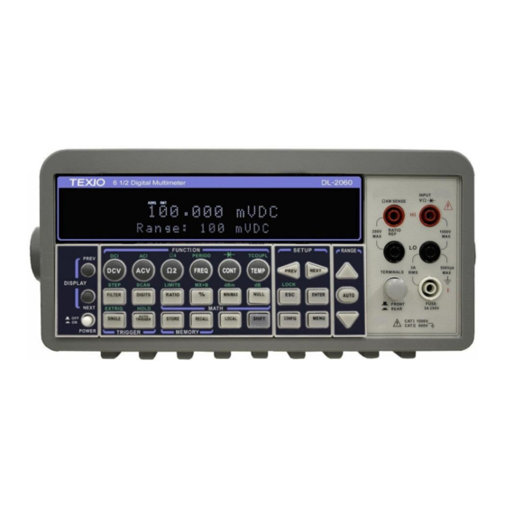
1.3 DL-2060 Function Introduction For users to become familiar with the DL-2060 DMM, we will give a brief introduction to the basic operations of DL-2060 DMM. There are three major parts of DL-2060: (1.3.1) the front panel, (1.3.2) the display, and (1.3.3) the rear panel. We will discuss each of them in the following sections. - Page 22 1. Power & Display: Power: Activates DL-2060 DMM. Display: Shows model, version & condition by pressing round PREV & NEXT buttons. 2-1. First row without SHIFT button: DCV: Selects DC voltage measurement. ACV: Selects AC voltage measurement.
-
Page 23: The Display
(Maximum current: 3A, 250V) 1.3.2 The Display DL-2060 has a 5x7 dot matrix, dual-display with three-color (White, Red and Yellow) annunciators for a better view. There are two rows in the dual-display screen. The upper row displays readings and units. A maximum 13 characters are allowed for upper row dot-matrix display. -
Page 24: Annunciators At Upper Side
Upper Row Display Lower Row Display Figure 2-17 1.3.2.1 Annunciators at Upper Side Figure 2-18 ADRS: Indicates the multimeter is controlled via GPIB Interface. RMT (REMOTE): Indicates the remote state. (USB Interface) MAN: Indicates the manual range is taken. ... -
Page 25: The Rear Panel
1.3.3 The Rear Panel The rear panel of the DL-2060 is shown in Figure 2-20. This figure includes important abbreviated information that should be reviewed before using the instrument. Fgure 2-20 1. Inserted Connections & Fuse Device: HI & LO: Used for all measurements, except AC & DC current and temperature. -
Page 26: Basic Measurement Function
2.1 Voltage Measurements (DC & AC) The ranges for DC voltage measurements in DL-2060 are 100mV, 1V, 10V, 100V and 1000V. For AC voltage measurements, the ranges are 100mV to 750V AC-Coupled TRMS or 1000V peak. - Page 27 Figure 3-1 Figure 3-2 ※ Note: The rear panel terminals can also be used via the same procedures as the front panel terminals. (Refer to Figure 3.3) Figure 3-3...
-
Page 28: Current Measurements (Dc & Ac)
2.2 Current Measurements (DC & AC) The ranges for DC current measurements in DL-2060 are 10mA, 100mA, 1A and 3A. For AC current measurements, the range is 1A with a sensitivity of 1 μA to 3A AC-Coupled TRMS with a sensitivity of 10μA. Figure 3-4 and 3-5 show you how to measure DC/AC currents in DL-2060. -
Page 29: Resistance Measurements (2 & 4-Wire)
※ Note: The rear terminal panel can also be used via the same procedures as the front panel. (See Figure 3-5) Figure 3-5 2.3 Resistance Measurements (2 & 4-wire) The ranges for resistance measurement are 100 Ω, 1KΩ, 10kΩ, 100kΩ, 1MΩ, 10MΩ, and 100MΩ, with a sensitivity of 100 μΩ... - Page 30 Figure 3-6 Figure 3-7 ※ Note: The rear terminal panel can also be used via the same procedures like the front panel as shown in Figures 3-8 and 3-9. Figure 3-8...
-
Page 31: Frequency & Period Measurements
Figure 3-9 2.4 Frequency & Period Measurements DL-2060 uses an on-board counter with 25MHz to measure the frequency (period). The measurement band is from 3Hz to 300kHz (or 333 ms to 3.3 μs) and the measurement voltages range from 100mV to 750 V in AC. The default for “RANGE” is auto-range. -
Page 32: Continuity Measurements
2.5 Continuity Measurements DL-2060 uses 1 K Ω range for the continuity measurement. The meter beeps when the test resistance is less than the threshold resistance. The default threshold resistance is 10Ω, but user can set the threshold resistance to anything between 1 Ω and 1 K Ω. The resistance value set by user is stored in a volatile memory and will be cleared after the meter has been turned off. -
Page 33: Diode Measurements
2.6 Diode Measurements DL-2060 uses a current source of 1 mA for diode testing. The maximum resolution is 10 μV on a fixed range of 1 V DC. The default threshold voltage is fixed between 0.3 and 0.8 volts and the reading rate is fixed at 0.1 PLC (The voltage bound is adjustable from 0.01V up to 1.2V.). -
Page 34: Temperature Measurements
The DL-2060 supports thermocouples and resistance temperature detector (RTD) types of probes. For thermocouples, DL-2060 supports 7 types: E, J, K, N, R, S and T. Please refer to Table 3-1 for their temperature ranges. Be sure that the temperature function is configured for the right sensor type before making measurements (Refer to 3.1.8 for... -
Page 35: Rtd Measurements
③ Configure the thermocouple type and unit using CONFIG + SHIFT + TCOUPL(TEMP), such as K TYPE and ºC. When ready, press ENTER button. ④ Press SHIFT + TEMP buttons. ⑤ Take the reading on the display. Figure 3-12 2.7.2 RTD Measurements There are three kinds of temperature measurements with RTDs: 2-wire, 3-wire and 4-wire measurements. -
Page 36: 3-Wire Rtd Measurements
2.7.2.2 3-Wire RTD Measurements How to measure temperature with 3-Wire RTD The following Figure 3-15 shows theory diagram of 3-Wire RTD measurement. ① Use terminals switch to select front terminals. ② Insert a specified adapter into the front terminals. ③ Configure sensor type and transducer as you would be with 4-wire RTD and unit using CONFIG + TEMP and ◁... - Page 37 Figure 3-17...
-
Page 38: Front Panel Operations
The purpose of Auto Zero functions are used for minimizing the offset influence on your measurements. When Auto Zero is enabled (no individual setup), DL-2060 takes the input signal reading as a base value and then internally disconnects the input signal, and takes a offset reading (a null offset). - Page 39 How to set Auto Zero You can change the Auto Zero setting through the front panel or through the remote interface operation. Front Panel Operation The following steps show how to set Auto Zero directly through the front panel. Be aware of that Auto Zero setting is always affected by the resolution setting. Whenever the resolution is altered, Auto Zero may be accordingly changed accordingly.
-
Page 40: Filter
3.1.2 Filter Filter is used to remove noises in measurement readings. DL-2060 is equipped with two types of filters: AC filter and digital filter. AC filter is for AC measurements only. It also affects the speed of the multimeter to yield a measurement reading. -
Page 41: Digital Filter
DETector:BANDwidth {3|20|200|MIN|MAX} 3.1.2.2 Digital Filter Definition: DL-2060 uses an averaging digital filter to yield a reading for display from a specified number of measurement readings in the past. The past measurement readings are stored in a stack of memory. The number may be in the range of 2 to 100. User may select one of the two modes of digital filter operations: Moving Average and Repeating Average. - Page 42 The moving average filter puts the specified number of reading conversions in a first-in, first-out order. The very first measurement reading simply fills up the stack. To yield a reading for display, the filter produces an average of the stacked measurement readings every time a new measurement reading is available and replaces the oldest reading in the stack.
-
Page 43: Resolution Setting (Digits)
3.1.3 Resolution Setting (Digits) Definition Resolution is the number of digits a multimeter can measure. User can select the resolution for a specific measurement. The choices for the resolution setting are: fast 4 1/2, slow 4 1/2, fast 5 1/2, slow 5 1/2, fast 6 1/2 and slow 6 1/2. For a higher accuracy, user can select 6 1/2 digit resolution. - Page 44 Press CONFIG and then select a function as you wish from DCV, DCI (SHIFT +DCV), Ω2, Ω4 (SHIFT + Ω2), FREQ and PERIOD (SHIFT + FREQ). Press ENTER on RESOLUTION submenu. If it is not shown on the display, use ◁ and ▷...
-
Page 45: Dc Input Resistance
3.1.4 DC Input Resistance Definition To reduce the effect of loading errors due to the input resistance, DL-2060 allows user to select a much larger input resistance (> 10G Ω) for low input DC voltage (100mV, 1V and 10V) measurements. This feature is only available for DC voltage measurements and it is not applicable to other measurement functions. -
Page 46: Threshold Resistance (Continuity)
Remote Interface Operation The automatic input resistance mode can be enabled / disabled. With AUTO OFF (default), the input resistance is fixed at 10MΩ for all ranges. With AUTO ON, the input resistance is set to >10GΩ for the three lowest DC voltage ranges (100mV, 1V and 10V). Use the following command from your PC terminal to disable the auto input DC resistance setting (the result is a fixed input DC resistance at 10M Ω... -
Page 47: Range (Manual & Auto)
3.1.6 Range (Manual & Auto) Definition When making measurements except CONT, DIODE and Temperature, you can let the machine choose ranges for you, or you can select the appropriate ranges manually by yourself. The difference between auto-range and manual-range is the settling time. Auto-range is a convenient way for user, but manual-range can usually speed up the process. -
Page 48: Rate (Integration Time)
The unit of the integration time is in PLC (power line cycles). One PLC for 60 Hz is 16.67 ms, and for 50 Hz is 20 ms. There are 4 different integration times in DL-2060 for user to select from: 0.02, 0.1, 1 and 10 PLC. -
Page 49: Sensor Selection For Temperature Measurements
SENSe:VOLTage:DC:NPLCycles? [MINimum|MAXimum] SENSe:CURRent:DC:NPLCycles {0.02|0.1|1|10|MINimum|MAXimum} SENSe:CURRent:DC:NPLCycles? [MINimum|MAXimum] SENSe:RESistance:NPLCycles {0.02|0.1|1|10|MINimum|MAXimum} SENSe:RESistance:NPLCycles? [MINimum|MAXimum] SENSe:FRESistance:NPLCycles {0.02|0.1|1|10|MINimum|MAXimum} SENSe:FRESistance:NPLCycles? [MINimum|MAXimum] For frequency and period measurements, aperture time (or gate time) is analogous to integration time, and you can use the following commands to set it. Specify 10 ms (4 1/2 digits), 100 ms (default;... - Page 50 Temperature Scale of 1990”. In each subrange, the calibration constants required for that subrange are listed. Default The default sensor type in DL-2060 is PT100. How to set up RTD You can set up the RTD configuration either through the front panel operation or through the remote interface operation.
- Page 51 Thermocouple Definition If users are using the thermocouple function, the selections on the DL-2060 are: type E, J, K, N, R, S and T. (On the other hand, other selection “SIMULATED” simulates the reference junction.) To use the the thermocouple function, users have to adjust something. First of all, via a thermocouple adaptor, users need to measure a known and accurate reference temperature (T1) as a criterion.
-
Page 52: Remote Interface Selection
PREV and NEXT to select the type and unit. 2. Measure a known and accurate reference temperature (T1). The result showing on the DL-2060 is (T2). 3. Adjust the simulated value (23.0°C to 23.0°C + T3.) 4. Configure the Simulated value by pressing CONFIG > SHIFT > TEMP(TCOUPL) > NEXT >... -
Page 53: Input Terminal Switch
Baudrate to set rate. Use ◁, ▷, △and ▽ to adjust the numbers to the desired rate. Press ENTER to set it. 3.1.10 Input Terminal Switch Definition User can select either the front input terminals or the rear input terminals for their measurements. -
Page 54: Trigger Operations
Following Figure 4-8 describes the detail of the trigger setup. Figure 4-8 The trigger system is supposed to be in an idle status when DL-2060 is not measuring. ( *(sampling)display will illuminates when measurement is in progress ) When starting measurement after idle status, the trigger system should be in trigger waiting status. -
Page 55: Trigger Mode
3.2.1 Trigger Mode There are three trigger modes in DL-2060: auto, immediate, and single triggering. User can specify the trigger mode for their measurement. The factory default is auto triggering when the meter is power-on. A. Auto Triggering Mode (Front Panel Operation only) -
Page 56: Trigger Source
Figure 4-10. Figure 4-10 3.2.2 Trigger Source In DL-2060, user can specify the trigger source to be one of these three options: front panel operations, external hardware trigger source and remote interface operations. Front Panel Operation Use the front panel buttons - AUTO TRIGGER for auto triggering and SINGLE for single triggering. - Page 57 annunciator on the display indicates the enabling of the external hardware trigger. The folloeing figure shows level and timming of a trigger pules. Figure EXT TRIG (Input) pulse riggere edge TTL: H (5V) TTL: L (0V) > 1µs VM COMP (Output) The rear-panel VM COMP (Voltmeter complete) terminal provides a low-true pulse (TTL level) after the completion of each measurement.
-
Page 58: Trigger Setting
3.2.3 Trigger Setting In DL-2060, user can specify a variety of trigger settings including the number of samples per trigger, the number of triggers per event, reading hold, and the trigger delay for their measurements. A. Number of samples on each trigger... - Page 59 Defaults The default of the trigger delay is automatic. DL-2060 automatically selects a delay time for you according to the setting of the measurement if you do not specify a delay. A list of the default for each measurement function is shown on Table 4-4. The range for the delay is from 0 to 3600 seconds.
- Page 60 The internal settings of automatic trigger delay The delay time for automatic trigger delay is determined by the selection of measurement function, range, and the setting of integration time and AC filter speed. The following table shows the default delay time for each measurement setting.
-
Page 61: Math Operations
TRIGger:DELay:AUTO {OFF|ON} 3.3 Math Operations This section will introduce the mathematical operations in DL-2060. There are eight math operations: RITIO, %, Min/Max, NULL, Limits, MX+B, dB and dBm testing. They either store data for later use or perform mathematical operations on the readings. Note that these math operations are available to all measurement functions except continuity and diode testing. -
Page 62: Ratio
3.3.1 Ratio This function calculates the ratio of an input DC voltage to a reference DC voltage according to the following equation: How to make a ratio measurement There are two ways to make a ratio measurement: Through the front panel operation or through the remote interface operation. -
Page 63: (Percent)
3.3.2 % (Percent) Definition This mathematical function calculates the ratio of a measurement reading to a specified target value as the form of percentage. The calculation formula is shown below: The specified target value is store in a volatile memory and will be cleared after the meter has been turned off or a remote interface reset. -
Page 64: Min/Max
3.3.3 Min/Max Definition When the Min/Max function is enabled, the multimeter takes in a series of readings from the measurements, stores the minimum and maximum readings in the memory, and then calculates the average value of all readings. The number of readings taken since Min/Max operation is enabled is recorded as well. -
Page 65: Null
CALCulate:STATe? CALCulate:AVERage:MINimum? CALCulate:AVERage:MAXimum? CALCulate:AVERage:AVERage? CALCulate:AVERage:COUNt? 3.3.4 Null Definition When null function is enabled, the displayed measurement reading is the difference between the measured input signal reading and the stored null (also called relative) value. The null (relative) value is stored in a volatile memory and the value will be cleared when the multimeter is power-off. -
Page 66: Limits Test
The Remote Interface Operation You can use the following commands on your PC terminal to make a null measurement. CALCulate:FUNCtion NULL CALCulate:STATe {OFF|ON} CALCulate:STATe? CALCulate:NULL:OFFSet {<value>|MAXimum|MINimum} 3.3.5 Limits Test The limits testing operation allows user to adjust a maximal and a minimal limit values. The multimeter beeps and an “HI”... - Page 67 CALCulate:LIMit:LOWer {<value>|MINimum|MAXimum} CALCulate:LIMit:LOWer? [MINimum|MAXimum] CALCulate:LIMit:UPPer {<value>|MINimum|MAXimum} CALCulate:LIMit:UPPer? [MINimum|MAXimum] Acquisition of limit test's result The result for Pass/Fail test may be aquired from the USB connector located at rear panel for DL-2060. Please refer "4.1 Pass/Fail output from USB connector" for detail.
-
Page 68: Mx+B
3.3.6 MX+B Definition This mathematical function multiplies a measurement reading (X) by a specified scale factor (M) and add an offset (B) automatically. The answer (Y) will then be shown on the display according to the following equation. Y=MX+B This is especially useful when user needs to do slope calculations on a series of measurements. - Page 69 Remote Interface Operation Use the following commands to enable and configure MX+B function: CALCulate:FUNCtion MXB CALCulate:STATe {OFF|ON} CALCulate:STATe? CALCulate:MXB:MMFactor {<value>|MINimum|MAXimum} CALCulate:MXB:MMFactor? [MINimum|MAXimum] CALCulate:MXB:MBFactor {<value>|MINimum|MAXimum} CALCulate:MXB:MBFactor? [MINimum|MAXimum]...
-
Page 70: Db/Dbm
3.3.7 dB/dBm A. dB Definition dB function will dB(decibel) indicates the difference after dBm convertion of both measured value and saved relative value. The dB measurement is applied to DC and AC voltage only. The range for the relative value is between 0 dBm and 200 dBm. - Page 71 Definition With dBm selected, a voltage measurement is displayed as the level of power, relative to 1 milliwatt, dissipated through a reference resistance. The reference resistance is adjustable in DL-2060. The calculation of dBm is defined as below: ...
- Page 72 Figure 4-23 How to make a dBm measurement Select a measurement function by pressing DCV or ACV button. The dBm feature is only available for DCV and ACV only. To enable dBm, press SHIFT + dBm(MIN/MAX) buttons. After enabling the dBm operation, user can select the reference resistance as mentioned above.
-
Page 73: Other System Related Operations
3.4.1 Display DL-2060 has a 5x7 dot matrix, dual-display with three-color (White, Red and Yellow) annunciators for a better view. A maximum 13 characters are allowed for upper row dot-matrix display and a maximum 16 characters are allowed for lower row dot-matrix display as shown on Figure 4-25. -
Page 74: Beeper
(clears the message displayed) 3.4.2 Beeper DL-2060 multimeter beeps when some certain conditions are met or when an error occurs. But there may be time you want to disable the beeper for some operations. Although you can turn off the beeper, the click sound you hear when a button is pressed will not be disabled. -
Page 75: Reading Memory (Store & Recall)
SYSTem:BEEPer:STATe {OFF|ON} 3.4.3 Reading Memory (Store & Recall) DL-2060 has a memory capacity of 2000 readings. The readings are stored in first-in-first-out order and the memory type is volatile, which means the stored readings will be cleared when the multimeter is power-off. The reading memory feature can be... - Page 76 User can store the readings and access to the stored readings through either the front panel operation or the remote interface operation. ※ Note: Each datum stored from DL-2060 to remote interface will be in a first in and first out condition.
-
Page 77: Sensitivity Band (Hold)
Figure 4-29 Remote Interface Operation Users can use the following commands from their PC terminals to store or retrieve readings in the memory. In addition, the number for STORE function only can be set through front panel. INITiate (This command tells the meter to be on “wait-for-trigger” state. After a measurement is taken, measurement readings will be placed in the memory.) FETCh? (Use this command to retrieve stored readings.) DATA:POINts? (Use this command to query the number of stored readings.) -
Page 78: Scanning (Scan)
Figure 4-30 3.4.5 Scanning (Scan) User can purchase an optional internal scanner card to be used with DL-2060 as the following picture shown. This multipoint scanner card lets you switch and scan up to 10 (or 20) channels of input signals. User can open and close individual channels, set scan count and scan interval, store measurement readings and activate measuring through channels defined with different measurement functions. - Page 79 200V peak btw any terminal and earth Max. Voltage btw Any Two Terminals 200V peak 160V peak Max. Voltage btw Any Terminal and 200V peak 160V peak DL-2060 Input LO DCI and ACI channels CH1,CH6 All channels CH1, CH11 Shunt installation...
- Page 80 Channel 1 Channel 2 Channel 3 OP-41, OP-41T OP-42 Channel 4 Channel 1 Channel 5 Channel 6 Channel 2 Channel 3 Channel 7 Channel 4 Channel 8 Channel 9 Channel 5 OUT A Channel 10 OUT A OUT B OUT B 4-Pole 2-Pole 4-Pole...
- Page 81 How to program each channel with measurement function Press CONFIG + SHIFT + DIGITS for scanning configuration. Use ◁ and ▷ to scroll through submenus. Press ENTER on “SET SCAN CHA” submenu. Use ◁ and ▷ to switch from channel 1 to channel 10 (or channel 20), and use △and ▽ to switch among the measurement functions.
-
Page 82: Stepping (Step)
3.4.6 Stepping (Step) User can purchase an optional internal scanner card to be used with DL-2060.Stepping is scanning with a specified time delay between taking input signal through the defined channels. ※ Note: Setting range of scanner card is only limited on DCV, DCI, ACV, ACI, Frequency, Period, Resistance, and RTD functions. -
Page 83: Method For Wiring To The Scanner Card
3.4.7 Method for wiring to the Scanner Card 【Step 1】 Open the cover of the case by gripping the part of the arrow as shown in the figure below. 【Step 2】 While opening the cover, release the lock by pushing in the direction of the arrow. (two places) 【Step 3】... - Page 84 Please insert the cable for OUT from the scanner card into the rear side input of DL-2060.When measuring 4 wires, please input into the SENSE input as well. When using the scanner card, please switch over the TERMINALS in front panel at REAR position.
-
Page 85: Method For Current Measurement On The Scanner Card
3.4.8 the Scanner Card Method for current measurement on Multi-point Scanner Card is not allowed of direct current measurements; however, on-card shunt resistors can be installed for Scanner Card to allow for indirect current measurements. How to put a resistor OP-41 Soldering the resistor on the channel to be measured at the surface of the land where parts of the OP-41’s PCB are installed. -
Page 86: Initial Mode
The section contains two selections: “DEFAULT” and “SAVE DATA”. You can select “SAVE DATE” to save the current configuration or select “DEFAULT” to restore the factory value after restarting DL-2060. The valid range of “SAVE DATA” is listed in Table 4-5. Table 4-5... -
Page 87: Language
Again use ◁ and ▷ to locate “LANGUAGE” submenu. Press ENTER to select it. Use ◁ and ▷ to switch to DEFAULT (DL-2060) or COMPATIBLE (Agilent 34401A). Press ENTER on your selection. The locations of the buttons are shown with red rectangle frames in Figure 4-34. -
Page 88: Firmware Revision
Figure 4-35. Figure 4-35 3.4.12 Firmware Revision DL-2060 has three microprocessors for various internal systems. You can query the multimeter to determine which revision of firmware is installed for each microprocessor. How to check the firmware revision Press MENU and then use ◁ and ▷ to locate “SYSTEM” submenu. Press ENTER to select it. -
Page 89: Calibration
Figure 4-36 3.4.13 Calibration ※ Notice: Do not use “CAL MENU” since it is aimed for maker calibration. 3.4.14 Self-test ※ Notice: Do not use “SELF TEST” since it is used only for an after sales service operation. -
Page 90: Remote Interface Operations
SCPI reference. 4.1 Pass/Fail Output From USB Connector The USB connector on the rear panel of DL-2060 is a type-B connector. When the USB interface is disabled (GPIB interface is selected), the internal pass and fail TTL output signals (limit testing) will be connected to the USB connector. -
Page 91: Setting Up For Remote Interface
Pass/Fail signal output abnormal. 4.2 Setting Up For Remote Interface DL-2060 may be remote controlled by USB or GPIB interface (only G type). Kind of interface should be selected in order to use remote interface. Please refer close 3.1.9 for detail of selection. - Page 92 omitted. The braces ({}) enclose the parameter choices for a given command string. The vertical bar (|) separates several choices for a parameter. The bold italic figure means a default parameters The MEASure? Command Although it does not offer much flexibility, using the MEASure? Command is the simplest way to program the multimeter for measurements.
- Page 93 FRESistance {<range>|MIN|MAX|DEF},{<resolution>|MIN|MAX|DEF} FREQuency {<range>|MIN|MAX|DEF},{<resolution>|MIN|MAX|DEF} PERiod {<range>|MIN|MAX|DEF},{<resolution>|MIN|MAX|DEF} CONTinuity DIODe TCOuple TEMPerature CONFigure? The READ? Command The READ? Command changes the state of the trigger system from the “idle” state to the “wait-for-trigger” state. When the specified trigger condition requirements are met after the multimeter receives the READ? command, the measurement will be initiated.
- Page 94 The SENSe Commands [SENSe:] FUNCtion “VOLTage:DC” FUNCtion “VOLTage:DC:RATio” FUNCtion “VOLTage:AC” FUNCtion “CURRent:DC” FUNCtion “CURRent:AC” FUNCtion “RESistance” (2-wire Ω) FUNCtion “FRESistance” (4-wire Ω) FUNCtion “FREQuency” FUNCtion “PERiod” FUNCtion “CONTinuity” FUNCtion “DIODe” FUNCtion “TCOuple” FUNCtion “TEMPerature” FUNCtion? [SENSe:] VOLTage:DC:RANGe {<range>|MINimum|MAXimum} VOLTage:DC:RANGe? [MINimum|MAXimum] VOLTage:AC:RANGe {<range>|MINimum|MAXimum} VOLTage:AC:RANGe? [MINimum|MAXimum] CURRent:DC:RANGe {<range>|MINimum|MAXimum}...
- Page 95 VOLTage:AC:RANGe:AUTO? CURRent:DC:RANGe:AUTO {OFF|ON} CURRent:DC:RANGeAUTO? CURRent:AC:RANGe:AUTO {OFF|ON} CURRent:AC:RANGe:AUTO? RESistance:RANGe:AUTO {OFF|ON} RESistance:RANGe:AUTO? FRESistance:RANGe:AUTO {OFF|ON} FRESistance:RANGe:AUTO? FREQuency:VOLTage:RANGe:AUTO {OFF|ON} FREQuency:VOLTage:RANGe:AUTO? PERiod:VOLTage:RANGe:AUTO {OFF|ON} PERiod:VOLTage:RANGe:AUTO? [SENSe:] VOLTage:DC:RESolution {<resolution>|MINimum|MAXimum} VOLTage:DC:RESolution? [MINimum|MAXimum] VOLTage:AC:RESolution {<resolution>|MINimum|MAXimum} VOLTage:AC:RESolution? [MINimum|MAXimum] CURRent:DC:RESolution {<resolution>|MINimum|MAXimum} CURRent:DC:RESolution? [MINimum|MAXimum] CURRent:AC:RESolution {<resolution>|MINimum|MAXimum} CURRent:AC:RESolutioin? [MINimum|MAXimum] RESistance:RESolution {<resolution>|MINimum|MAXimum} RESistance:RESolution? [MINimum|MAXimum] FRESistance:RESolution {<resolution>|MINimum|MAXimum} FRESistance:RESolution? [MINimum|MAXimum] [SENSe:]...
- Page 96 [SENSe:] TEMPerature:RTD:TYPE {PT100|D100|F100|PT385|PT3916|USER|SPRTD|NTCT} TEMPerature:RTD:TYPE {PT100|D100|F100|PT385|PT3916|USER|SPRTD|NTCT}, @{scanner channel number} TEMPerature:RTD:TYPE? TEMPerature:RTD:TYPE? @{scanner channel number} TEMPerature:RTD:RZERo {<value>|MINimum|MAXimum} TEMPerature:RTD:RZERo? [MINimum|MAXimum] TEMPerature:RTD:ALPHa {<value>|MINimum|MAXimum} TEMPerature:RTD:ALPHa? [MINimum|MAXimum] TEMPerature:RTD:BETA {<value>|MINimum|MAXimum} TEMPerature:RTD:BETA? [MINimum|MAXimum] TEMPerature:RTD:DELTa {<value>|MINimum|MAXimum} TEMPerature:RTD:DELTa? [MINimum|MAXimum] TEMPerature:SPRTD:RZERo {<value>|MINimum|MAXimum} TEMPerature:SPRTD:RZERo? [MINimum|MAXimum] TEMPerature:SPRTD:A4 {<value>|MINimum|MAXimum} TEMPerature:SPRTD:A4? [MINimum|MAXimum] TEMPerature:SPRTD:B4 {<value>|MINimum|MAXimum} TEMPerature:SPRTD:B4? [MINimum|MAXimum] TEMPerature:SPRTD:AX {<value>|MINimum|MAXimum} TEMPerature:SPRTD:AX? [MINimum|MAXimum] TEMPerature:SPRTD:BX {<value>|MINimum|MAXimum}...
- Page 97 RESistance:NPLCycles {0.02|0.1|1|10|MINimum|MAXimum} RESistance:NPLCycles? [MINimum|MAXimum] FRESistance:NPLCycles {0.02|0.1|1|10|MINimum|MAXimum} FRESistance:NPLCycles? [MINimum|MAXimum] [SENSe:] FREQuency:APERture {0.01|0.1|1|MINimum|MAXimum} FREQuency:APERture? [MINimum|MAXimum] PERiod:APERture {0.01|0.1|1|MINimum|MAXimum} PERiod:APERture? [MINimum|MAXimum] [SENSe:] DETector:BANDwidth {3|20|200|MINimum|MAXimum} DETector:BANDwidth? [MINimum|MAXimum] [SENSe:] AVERage:TCONtrol {MOVing|REPeat} AVERage:TCONtrol? AVERage:COUNt {<value>|MINimum|MAXimum} AVERage:COUNt? [MINimum|MAXimum] AVERage:STATe {OFF|ON} AVERage:STATe? [SENSe:] ZERO:AUTO {OFF|ONCE|ON} ZERO:AUTO? INPut: IMPedance:AUTO {OFF|ON} IMPedance:AUTO? Scanner Card Configuration Commands ROUTe:CLOSe <channel>...
- Page 98 ROUTe:SCAN:TIMER <value> ROUTe:SCAN:COUNT? ROUTe:SCAN:COUNT <value> ROUTe:SCAN:STATe? ROUTe:SCAN:SCAN ROUTe:SCAN:STEP MATH OPERATION Commands There are eight math operations. Only one of them can be enabled at a time. They either store data for later use or perform mathematical operations on the readings. Note that these eight math operations are available to all measurement functions except continuity and diode testing.
- Page 99 DATA:FEED? TRIGGERING DL-2060 provides a variety of trigger operations for user. User can select a trigger mode, a trigger source and different trigger settings for a specific measurement. Refer to Figure 4-8 for triggering system flow chart. Triggering from a remote interface is a multi-step sequence.
- Page 100 TRIGger: DELay {<seconds>|MINimum|MAXimum} DELay? [MINimum|MAXimum] TRIGger: DELay:AUTO {OFF|ON} DELay:AUTO? SAMPle: COUNt {<value>| MINimum|MAXimum } COUNt? [MINmum|MAXimum ] TRIGger: COUNt {<value>| MINimum|MAXimum|INFinite } COUNt? [MINmum|MAXimum] SYSTEM-RELATED Commands Each system related operation performs a task that is not measurement related but plays an important role in making your measurements. FETCh? READ? DISPlay {OFF|ON}...
- Page 101 STATUS REPORTING Commands SYSTem:ERRor? STATus: QUEStionable:ENABle <enable value> QUEStionable:ENABle? QUEStionable:EVENt? STATus:PRESet *CLS *ESE <enable value> *ESE? *ESR? *OPC *OPC? *PSC {0|1} *PSC? *SRE <enable value> *SRE? *STB?
- Page 102 Other Interface Commands SYSTem:LOCal SYSTem:REMote GPIB (IEEE-488.2) COMMON Commands *CLS *ESE <enable value> *ESE? *ESR? *IDN? *OPC *OPC? *PSC {0|1} *PSC? *RST *SRE <enable value> *SRE? *STB? *TRG...
-
Page 103: Error Message
When user has read all errors from the queue, the ERROR annunciator turns off. DL-2060 beeps once each time an error occurs. Should more than 20 errors have existed, the last error stored in the queue (the most recent error) is replaced with -350, “Too many errors”. - Page 104 -108 Parameter not allowed More parameters were found than needed for the command . -109 Missing parameter Not enough parameters were received for the command. -112 Program mnemonic too long A command header with too many characters was received. ...
- Page 105 -170~-178 Expression errors The meter does not accept mathematical expression. -211 Trigger ignored A Group Execute Trigger (GET) or *TRG was received but the trigger was ignored. -213 Trigger deadlock A trigger deadlock occurs when the trigger source is BUS and a READ? Command is received ...
- Page 106 -420 Query UNTERMINATED The multimeter was addressed to talk (i.e., to send data over the interface) but a command has not been received which send data to the output buffer. -430 Query DEADLOCKED A command was received which generates too much data to fit in the output buffer and input buffer is also full.
-
Page 107: Appendix
Appendix A. Specification List 1 DC Characteristics Accuracy ± (% of reading + % of range) 2 1 Year (23 ± 5 Function Range Resolution Input resistance ℃ ℃ 100.0000 mV 0.1 μV > 10 GΩ 0.0050 + 0.0035 1.000000 V 1.0 μV >... - Page 108 1 Year (23 ± 5 Function Range Resolution Test Current ℃ ℃ 100.0000 Ω 100 μΩ 1 mA 0.010 + 0.004 1.000000 kΩ 1 mΩ 1 mA 0.010 + 0.001 10.00000 kΩ 10 mΩ 100 μA 0.010 + 0.001 Resistance 100.0000 kΩ...
- Page 109 5 Frequency and Period Characteristics Accuracy ± (% of reading) 6 Function Frequency (Hz) 1 Year (23 ±5 Range ℃ ℃ 3 – 5 0.10 Frequency 100 mV 5 – 10 0.05 & 10 – 40 0.03 9 Period 750 V 40 –...
- Page 110 General Specifications Item Limitation & description Power Supply 100 V / 220 V ± 10% Power Line Frequency 50 / 60 Hz ± 10% Power Consumption 25 VA max 0 ℃ to 50 ℃ Operating Temperature Maximum relative humidity 80 % Operating Humidity for temperature up to 31 ℃...
-
Page 111: Remote Interface Reference
B. Remote Interface Reference B.1 An Introduction to the SCPI Language SCPI (Standard Commands for Programmable Instruments) is an ASCII-based instrument command language designed for test and measurement instruments. SCPI commands are based on a hierarchical structure, also known as a tree system. In this system, associated commands are grouped together under a common node or root, thus forming subsystems. - Page 112 The command syntax shows most commands (and some parameters) as a mixture of upper- and lower-case letters. The upper-case letters indicate the abbreviated spelling for the command. For shorter program lines, send the abbreviated form. For better program readability, send the long form. For example, in the above syntax statement, VOLT and VOLTAGE are both acceptable forms.
- Page 113 ※ Note: If you send two query commands without reading the response from the first, and then attempt to read the second response, you may receive some data from the first response followed by the complete second response. To avoid this, do not send a query command without reading the response.
- Page 114 Discrete Parameters Discrete parameters are used to program settings that have a limited number of values (like BUS, IMMediate, EXTernal). They have a short form and a long form just like command keywords. You can mix upper- and lower-case letters. Query responses will always return the short form in all upper-case letters.
-
Page 115: Output Data Formats
B.2 Output Data Formats Output data will be in one of formats shown in the table below. Type of Output Data Non-reading queries Single reading (GPIB) Multiple readings (GPIB) Output Data Format < 80 ASCII character string SD.DDDDDDDDESDD<nl> SD.DDDDDDDDESDD,...,...,<nl> SD.DDDDDDDDESDD<cr><nl> SD.DDDDDDDDESDD,...,...,<cr><nl>... - Page 116 MEASure:CURRent:AC? {<range>|MIN|MAX|DEF},{<resolution>|MIN|MAX|DEF} Preset and make a AC current measurement with the specified range and resolution. The reading is sent to the output buffer. For AC measurement, resolution is fixed at 6 ½ digits. Therefore the resolution parameter only affects the front panel display. MEASure:RESistance? {<range>|MIN|MAX|DEF},{<resolution>|MIN|MAX|DEF} Preset and make a 2-wire Ω...
-
Page 117: The Configure Command
B.4 The CONFigure Command CONFigure:VOLTage:DC {<range>|MIN|MAX|DEF},{<resolution>|MIN|MAX|DEF} Preset and configure the multimeter for DC voltage measurements with the specified range and resolution. This command does not initiate the measurement. CONFigure:VOLTage:DC:RATio {<range>|MIN|MAX|DEF },{<resolution>|MIN|MAX|DEF} Preset and configure the multimeter for DC:DC ratio measurements with the specified range and resolution. - Page 118 CONFigure:PERiod {<range>|MIN|MAX|DEF},{<resolution>|MIN|MAX|DEF} Preset and configure a period measurement with the specified range and resolution. This command does not initiate the measurement. For period measurements, the meter uses only one “range” for all inputs between 0.33 seconds and 3.3 µsec. With no input signal applied, period measurements return “0”.
-
Page 119: The Measurement Configuration Command
B.5 The Measurement Configuration Command This mark means that it is available with firmware version 1.05 or upward. ※ [SENSe:]FUNCtion “<function>” Select a measurement function and enclose it in quotes in the command string (FUNC “VOLT:DC”). Use one of the following strings. VOLTage:DC VOLTage:AC VOLTage:DC:RATio... - Page 120 [SENSe:]UNIT? Query units for temperature measurement. [SENSe:]TCOuple:TYPE {E|J|K|N|R|S|T} Select thermocouple sensor type. [SENSe:]TCOuple:TYPE {E|J|K|N|R|S|T}, @{scanner channel number} Set a thermocouple sensor type on an indicated channel. [SENSe:]TCOuple:TYPE? Query thermocouple sensor type. [SENSe:]TCOuple:TYPE? @{scanner channel number} Query thermocouple sensor type on an indicated channel. ※...
- Page 121 [SENSe:]TEMPerature:RTD:RZERo {<value>|MINimum|MAXimum} Set the R-Zero constant for the user defined RTD type. [SENSe:]TEMPerature:RTD:RZERo? [MINimum|MAXimum] Query the R-Zero constant for the user defined RTD type. [SENSe:]TEMPerature:RTD:ALPHa {<value>|MINimum|MAXimum} Set the alpha constant for the user type. [SENSe:]TEMPerature:RTD:ALPHa? [MINimum|MAXimum] Query the alpha constant for the user type. [SENSe:]TEMPerature:RTD:BETA {<value>|MINimum|MAXimum} Set the beta constant for the user type.
- Page 122 [SENSe:]TEMPerature:SPRTD:AX {<value>|MINimum|MAXimum} Set the A coefficient. [SENSe:]TEMPerature:SPRTD:AX? [MINimum|MAXimum] Query the A coefficient. [SENSe:]TEMPerature:SPRTD:BX {<value>|MINimum|MAXimum} Set the B coefficient. [SENSe:]TEMPerature:SPRTD:BX? [MINimum|MAXimum] Query the B coefficient. [SENSe:]TEMPerature:SPRTD:CX {<value>|MINimum|MAXimum} Set the C coefficient. [SENSe:]TEMPerature:SPRTD:CX? [MINimum|MAXimum] Query the C coefficient. [SENSe:]TEMPerature:SPRTD:DX {<value>|MINimum|MAXimum} Set the D coefficient. [SENSe:]TEMPerature:SPRTD:DX? [MINimum|MAXimum] Query the D coefficient.
- Page 123 [SENSe:]<function>:NPLCycles {0.02|0. 1|1|10|MINimum|MAXimum} Set the integration time in number of power line cycles for the selected function. This command is valid only for DCV, DCI, 2-wire ohms and 4-wire ohms. [SENSe:]<function>:NPLCycles? [MINimum|MAXimum] Query the integration time for the selected function. [SENSe:]FREQuency:APERture {0.01|0.1|1|MINimum|MAXimum} Set the gate time (or aperture time) for frequency function.
- Page 124 ROUTe:TERMinals? Query the multimeter to determine if the front or rear input terminals are selected. Returns "FRON" or "REAR" ROUTe:CLOSe <channel> Set channels which need to be closed. <The range is from channel 1 to 10 or 20> ROUTe:CLOSe? Query channels which were closed. ROUTe:OPEN Open all channels.
-
Page 125: The Math Operation Command
ROUTe:SCAN:SCAN Run SCAN mode ROUTe:SCAN:STEP Run STEP mode B.6 The Math Operation Command CALCulate:FUNCtion {PERCent|AVERage|NULL|LIMit|MXB|DB|DBM} Select the math function. Only one function can be enabled at a time. The default function is percent. CALCulate:FUNCtion? Query the present math function. Returns PERC, AVER, NULL, LIM, MXB, DB or DBM. CALCulate:STATe {OFF|ON} Disable or enable the selected math function. - Page 126 CALCulate:AVERage:COUNt? Read the number of readings taken since Min/Max has been enabled. The multimeter clears the value when Min/Max is turned on, when the power has been off or a remote interface reset. CALCulate:NULL:OFFSet {<value>|MINimum|MAXimum} Store a null value in the multimeter’s Null Register. You must turn on the math operation before ...
-
Page 127: The Triggering Commands
CALCulate:DB:REFerence? [MINimum|MAXimum] Query the dB relative value. CALCulate:DBM:REFerence {<value>|MINimum|MAXimum} Set the dBm reference value. Choose from: 50 ~ 8000 ohms. CALCulate:DBM:REFerence? [MINimum|MAXimium] Query the dBm reference value. DATA:FEED RDG_STORE,{“CALCulate”|””} Selects whether readings taken using the INITiate command are stored in the multimeter’s internal memory (default) or not stored at all. - Page 128 TRIGger:SOURce? Query the trigger source. TRIGger:DELay {<seconds>|MINimum|MAXimum} Set a trigger delay time in seconds. The delay is the time between the trigger signal and each sample that follows. Specify a delay time from 0 to 3600 seconds. TRIGger:DELay? Query the trigger delay time. TRIGger:DELay:AUTO {OFF|ON} Disable or enable a automatic trigger delay.
-
Page 129: The System-Related Commands
B.8 The System-Related Commands FETCh? Transfer readings stored in memory by the INITiate command to output buffer where you are able to read them into your bus controller. READ? Change the state of the triggering system from the “idle” state to “wait-for-trigger” state. The meter will start to make measurements when a required triggering condition is met after the READ? command is received. -
Page 130: Status Reporting Commands
SYSTem:VERSion? Query the present SCPI version. Set to the default identification string. Set to the compatible identification string. DATA:POINts? Query the number of readings stored in the multimeter’s internal memory. *RST Reset the multimeter to the power-on configuration. This command can not clear the error queue. *IDN? Read the multimeter’s identification string (be sure to dimension a string variable with at least 35 characters). - Page 131 STATus:QUEStionable:EVENt? Query the Questionable Data event register. The multimeter returns a decimal value which corresponds to the binary-weighted sum of all bits set in the register. STATus:PRESet Clear all bits in the Questionable Data enable register. *CLS Clear the Status Byte summary register and all event registers. *ESE <enable value>...
-
Page 132: Scpi Compliance Information
“request service” bit (bit 6) is not cleared if a serial poll has occurred. B.10 SCPI Compliance Information This section encloses a list of commands that are device-specific to the DL-2060. Although not included in the 1999.0 version of the SCPI standard, these commands are designed with the SCPI format in mind and they follow all of the syntax rules of the standard. - Page 133 CALCulate: PERCent:TARGet {<value>|MINimum|MAXimum} PERCent:TARGet? [MINimum|MAXimum] AVERage:MINimum? AVERage:MAXimum? AVERage:AVERage? AVERage:COUNt? NULL:OFFSet {<value>|MINimum|MAXimum} NULL:OFFSet? [MINimum|MAXimum] LIMit:LOWer {<value>|MINimum|MAXimum} LIMit:LOWer? [MINimum|MAXimum] LIMit:UPPer {<value>|MINimum|MAXimum} LIMit:UPPer? [MINimum|MAXimum] MXB:MMFactor {<value>|MINimum|MAXimum} MXB:MMFactor? [MINimum|MAXimum] MXB:MBFactor {<value>|MINimum|MAXimum} MXB:MBFactor? [MINimum|MAXimum] DB:REFerence {<value>|MINimum|MAXimum} DB:REFerence? [MINimum|MAXimum] DBM:REFerence {<value>|MINimum|MAXimum} DBM:REFerence? [MINimum|MAXimum] CONFigure: CONTinuity DIODe INPut: IMPedance:AUTO {OFF|ON} IMPedance:AUTO?
-
Page 134: Gpib (Ieee-488) Compliance Information
B.11 GPIB (IEEE-488) Compliance Information GPIB Common Commands *CLS *ESE <enable value> *ESE? *ESR? *IDN? *OPC *OPC? *PSC {0|1} *PSC? *RST *SRE <enable value> *SRE? *STB? *TRG Using Device Clear to Halt Measurements Device clear is an GPIB low-level bus message which can be used to halt measurements in progress. -
Page 135: Tree Diagram
C. Tree Diagram Please refer to G. Notice of Scanner Card if your firmware version is 1.05 or upward. -
Page 138: Dl-2060'S Dimension
D. DL-2060’s Dimension... -
Page 139: About Application Programs
NI-VISA is trademark of National Instruments Corp. Visual Basic 6 and VBA(Excel) Learn how to create and use TEXIO IOUtils components, controls, data access, and more with the following Visual Basic 6 sample applications. E.1 Using MEASure? for a Single Measurement The following example uses the MEASure? command to make a single ac current measurement. - Page 140 Rem send measure command -- Set to 0.1 volt dc range stat = viWrite(sesn, "meas:volt:DC? 0.1,0.01", 22, ret) If (stat < VI_SUCCESS) Then MsgBox "System command error. (meas:volt:dc? ...)", vbExclamation, "DL-2060 multimeter device test" stat = viClose(fList) Exit Sub End If...
-
Page 141: Using Configure With A Math Operation
' Array index stat = viOpenDefaultRM(dfltRM) If (stat < VI_SUCCESS) Then 'Rem Error initializing VISA ... exiting MsgBox "USBTMC resource not found.", vbExclamation, "DL-2060 multimeter device test" Exit Sub End If Rem Find all DL-2060 USBTMC instruments in the system stat = viFindRsrc(dfltRM, "USB[0-9]*::0x098F::0x2061::?*INSTR", fList, nList, desc) - Page 142 = viWrite(sesn, "*RST", 4, ret) If (stat < VI_SUCCESS) Then MsgBox "System command error. (*RST)", vbExclamation, "DL-2060 multimeter device test" stat = viClose(fList) Exit Sub End If Rem send Clear command '*CLS'-- Clear DL-2060 status register stat = viWrite(sesn, "*CLS", 4, ret) If (stat <...
- Page 143 Sleep (3000) ' wait for math processing Rem fetch the measure data stat = viRead(sesn, readin, 128, ret) If (stat < VI_SUCCESS) Then MsgBox "Read in data error.", vbExclamation, "DL-2060 multimeter device test" stat = viClose(fList) Exit Sub End If Rem set to local mode stat = viWrite(sesn, "system:local", 12, ret)
-
Page 144: The Devquery Function
Visual C++ This C++ sample application is a Win32 console application. It illustrates how to use the TEXIO IOUtils command. A Win32 console application is a Win32 application that uses text-based input and output, not a graphical interface. This allows you to quickly create a Win32 application by using simple input and output functions. - Page 145 == NULL || PviSetAttribute_usb == NULL FreeLibrary (hUSBTMCLIB); hUSBTMCLIB = NULL; MessageBox(NULL, "NIVISA for USBTMC library not ready.", "DL-2060 multimeter device test", MB_OK); return; printf("\n ###### Start C++ Example program. ######\n"); printf(" We check the DL-2060 multimeter on USB port and\n");...
- Page 146 PviOpen_usb(m_defaultRM_usbtmc, instrDescriptor, 0, 0, &m_instr_usbtmc); status = PviSetAttribute_usb(m_instr_usbtmc, VI_ATTR_TMO_VALUE, m_Timeout); if (!hUSBTMCLIB) printf("DL-2060 device connect failed.\n"); return; // Write command "*IDN?" and read the DL-2060 identification string len = 64; pStrout = new char[len]; ZeroMemory(pStrout, len); strcpy(pStrout, "*idn?"); status = PviWrite_usb(m_instr_usbtmc, (unsigned char *)pStrout, 6, &nWritten);...
- Page 147 // Set configure Current DC, range 0.1A strcpy(pStrout, "CONF:CURR:DC 1,0.01"); status = PviWrite_usb(m_instr_usbtmc, (unsigned char *)pStrout, 20, &nWritten); Sleep(3000); // Fetch the DL-2060 measure value ( screen value ) // Set Voltage DC measure strcpy(pStrout, "CONF:VOLT:DC 0.1,0.1"); status = PviWrite_usb(m_instr_usbtmc, (unsigned char *)pStrout, 21, &nWritten);...
-
Page 148: Resolution And Nplc Correlation Table
F. Resolution and NPLC correlation table ※ For DC voltage, DC current, and Resistance measurements, the integration time is set indirectly when user selects the measurement resolusion. SENS:VOLT:DC:RES <resolution> MEAS:VOLT:DC? <range>,<resolution> CONF:VOLT:DC <range>,<resolution> Front Panel [SENS:] Resolution [SENS:] Default Range Resolution NPLC <range>,<resolution>... - Page 149 ○ FAST 4 1/2 digits 10.000 KΩ +1.000000E+0 +2.000000E-02 10000 , 1 ○ ○ SLOW 4 1/2 digits 10.000 KΩ +1.000000E-01 0.1 +1.000000E-01 ○ FAST 5 1/2 digits 10.0000 KΩ +1.000000E-01 0.1 +1.000000E-01 10000 , 0.1 10 kΩ ○ ○ ◎...
- Page 150 ※ The resolution setting for AC measurements is actually fixed at 6 1/2 digits. When user selects a lower resolution, the meter will mask out the extra digits. User’s selection of resolution for AC function will not affect the actual speed or accuracy.
-
Page 151: Notice Of Scanner Card
The TCOUPL function on the front panel will be disenabled automatically. You can only use the Card for thermocouple measurement. You can only use REAL mode for RJUNCTION. While installing the Scanner Card(except OP-41T) in DL-2060 REAL and VIEW REAL functions are unavailable. - Page 152 7F Towa Fudosan Shin Yokohama Bild. 2-18-13, Shin Yokohama, Kohoku-ku,Yokohama, Kanagawa, 222-0033 Japan http://www.texio.co.jp/...
Need help?
Do you have a question about the DL-2060 and is the answer not in the manual?
Questions and answers