Table of Contents
Advertisement
CAUTION
● Read this manual before use and installation.
● This equipment must be installed by qualified personnel according to
applicable standards in order to prevent injury or damage to property.
● Before any maintenance operation on the device, remove all voltages from measuring and supply inputs.
● The manufacturer cannot be held responsible for electrical safety in case of improper use of the equipment.
● The product illustrated herein are subject to alteration and changes without prior notice. Descriptions and information in the catalogue consequently have no contractual relevance.
● A circuit breaker must be included in the electrical installation of the building. It must be installed close by the equipment and within easy of the operator. It must be marked as the equipment's
disconnecting device: IEC/ EN 61010-1 § 6.12.2.1.
● Clean the equipment with a soft cloth; do not use abrasive products, liquid detergents or solvents.
Doc: I437GB04_16.docx
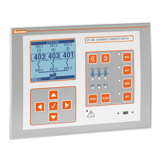
ATL900
AUTOMATIC TRANSFER SWITCH
INSTRUCTION MANUAL
Contents
Parameter setting via NFC
Connection diagrams
Mechanical dimensions and panel perforation
Page
2
2
2
2
3
3
3
4
4
4
5
6
6
7
7
7
7
8
8
8
8
8
9
9
9
9
10
11
23
23
23
24
25
26
26
27
28
31
32
32
35
36
37
38
09/03/2016
p. 1 / 37
Advertisement
Table of Contents

Subscribe to Our Youtube Channel
Related Manuals for LOVATO ELECTRIC ATL900


Summary of Contents for LOVATO ELECTRIC ATL900
-
Page 1: Table Of Contents
ATL900 AUTOMATIC TRANSFER SWITCH INSTRUCTION MANUAL CAUTION ● Read this manual before use and installation. ● This equipment must be installed by qualified personnel according to applicable standards in order to prevent injury or damage to property. ● Before any maintenance operation on the device, remove all voltages from measuring and supply inputs. -
Page 2: Introduction
Introduction The ATL900 control unit implements state-of-the-art functions required for automatic transfer applications. The system incorporates a unique series of hardware and software features which guarantee high flexibility, e.g. management of three supply source lines and two tie breakers, graphic display, double power supply, expansion modules, programmable system layout, integrated PLC etc., for use in a wide variety of possible conditions of application, all of which can be programmed by the user. -
Page 3: Operating Modes
Energising the equipment ATL900 has two power supplies: 100-240VAC or 12-24-48VDC. Priority is given to the AC power if both are present at the same time. The equipment is normally set to the OFF mode when it is switched on. Modify parameter P01.03 in the M01 Utility menu if the operating mode selected before switch-off must be maintained. -
Page 4: Password Protected Access
Password protected access The password is used to enable or block access to the setting menu and the command menu. The password is deactivated and access is free on new equipment (default). If the passwords are enabled, they must be entered to access the equipment (the passwords are numeric). -
Page 5: Display Pages Table
Display pages table PAGES EXEMPLE PAGES EXEMPLE Phase to Phase phase voltage voltage Alarm status Control thresholds Statistics Events list Battery status Expansion modules Inputs and Inputs outputs status Outputs Date / Time System info Automatic test Doc: I437GB04_16.docx 09/03/2016 p. -
Page 6: Expandability
Expandability With its expansion bus, the ATL900 can be expanded with the additional modules of the EXP…. series. Up to three EXP… modules can be installed at the same time. The EXP… modules supported by the ATL900 are divided into the following categories:... -
Page 7: Communication Channels
The communication channels may operate at the same time. By activating the Gateway function, it is possible to have an ATL900 equipped with an Ethernet port and the basic RS-485 port which works as a ‘bridge’ towards the other devices provided with the RS-485 port only, so obtain a saving (one Ethernet access point only). -
Page 8: Remote Variables (Remx)
See settings menu M21 for alarm definition. PLC logic (PLCx) Xpress can be set using a ladder program for creating a PLC internal logic inside the ATL900, so as to be able to freely create any function necessary for genset accessory applications. -
Page 9: Ir Programming Port
CX01 USB Dongle and CX02 WiFi Dongle Parameter setting from PC The configuration and remote monitoring software Xpress can be used to transfer the set-up parameters (previously set) from ATL900 to the PC hard disk and vice versa. ... -
Page 10: Parameter Settings (Setup) From Front Panel
Parameter settings (setup) from front panel To access the parameter programming menu (setup): Set the board to OFF mode On the normal measurement display, press ▲ and ▼at the same time to recall the main menu Select the icon . -
Page 11: Parameter Table
Parameter table M01 - UTILITIES Unit Default Range P01.01 Language English English Italiano Francais Espanol Deutsch Portuguese Polish Russian P01.02 Clock setting after power-on OFF-ON P01.03 Power-on operative mode Previous OFF mode Previous P01.04 LCD contrast 0-100 Display backlighting intensity high 0-100 P01.05... - Page 12 P02.16 Non-priority load management Pulse breaker Continuous breaker Contactor P02.17 Breaker operation max. time non-priority load 1…900 P02.18 Open pulse time 0-600 P02.19 Close pulse time 0-600 P02.20 Minimum coil opening pulse time 0.1 … 10.0 P02.21 Delay between min. coils and spring load 0.1 …...
- Page 13 P04.04 - Tripping delay between MIN and MAX battery alarms. P04.05-P04.06-P04.07-P04.08 - Serial communication enabling between ATL900 and any BCG…RS series communicating battery chargers. It allows to read the voltages, charging currents and alarms concerning the corresponding battery charger and to view information on the dedicated video page. ‘Local’ means the battery charger connected to the battery which powers the ATL900 in DC.
- Page 14 P07.n.09 - Time elapsed between minimum voltage opening pulse and breaker spring loading control. P07.n.10 - This defines whether in case of failure to close the ATL900 must perform a retry consisting of a cycle of opening/spring recharging cycles followed by a new closing attempt.
- Page 15 M08 - SWITCH Unit Default Range P08.01 Transfer device type Pulse control breakers Pulse control brk. Continuous control brk. Contactor P08.02 Transfer strategy P08.03 Maximum load not powered time OFF / 1…3600 (alarm A09 tripping delay) P08.04 Automatic return on priority line inhibition OFF / ON P08.05 Genset start delay...
- Page 16 P08.21 - P08.22 - These define the ON and OFF time of the pulse controls for increasing or decreasing the voltage or frequency, respectively. These times influence the programmed outputs with the increase voltage, decrease voltage, increase frequency and decrease frequency functions. The signals are intended to be sent to a genset control unit with the purpose of reaching synchronisation conditions.
- Page 17 7 bit, odd 7 bit, even P10.n.04 Stop bit P10.n.05 Protocol Modbus RTU Modbus RTU Modbus ASCII Modbus TCP P10.n.06 IP address 192.168.1.1 000.000.000.000 – 255.255.255.255 P10.n.07 Subnet mask 0.0.0.0 000.000.000.000 – 255.255.255.255 P10.n.08 IP port 1001 0-32000 P10.n.09 Channel function Slave Slave Gateway...
- Page 18 Note: This menu is divided into 16 sections for limit thresholds LIM1..16. P15.n.01 - This defines which measurements supplied by the ATL900 to apply the limit threshold. P15.n.02 - If the reference measurement is an electric measurement, this defines whether it refers to the mains or the genset.
- Page 19 Note: This menu is divided into 8 sections for counters CNT1..8. P16.n.01 - Signal which causes the counter increments (on ramp up). It may be energised by the ATL900 (ON), the exceeding of a threshold (LIMx), the activation of an external input (INPx), a logical condition (PLCx) etc.
- Page 20 M19 - ANALOG INPUTS Unit Default Range (AINn, n=1…6) P19.n.01 Input type 0..20mA 4….20mA 0…10V -5V…+5V PT100 P19.n.02 Start scale value -9999 - +9999 P19.n.03 Multiplier /100 - x1k P19.n.04 Full scale value -9999 - +9999 P19.n.05 Multiplier /100 - x1k P19.n.06 Description AINn...
-
Page 21: Alarms
M21 - USER ALARMS Unit Default Range (UAn, n=1…8) P21.n.01 Alarm source INPx OUTx LIMx REMx PLCx TIMx P21.n.02 Channel no. (x) OFF/1...99 P21.n.03 Text (text - 20 characters) P21.n.04 Breaker 1 open P21.n.05 Breaker 2 open P21.n.06 Breaker 3 open Note: This menu is divided into 8 sections for defining the user alarms UA1…UA8. -
Page 22: Alarm Properties
Alarm properties Various properties can be assigned to each alarm, including the user alarms (User Alarms, Uax): Enabled alarm – General alarm enable. If not enabled, it is as if it does not exist. AUT only – The alarm may only be generated when ATL is in automatic mode. ... -
Page 23: Description Of The Alarms
Description of the alarms CODE DESCRIPTION REASON FOR THE ALARM Battery voltage too low Battery voltage under minimum threshold for a time longer than set. Battery voltage too high Battery voltage under maximum threshold for a time longer than set. BRK1 breaker timeout Breaker BRK1 of line SRC1 did not perform the opening or closing operation before the timeout. -
Page 24: Programmable Inputs Functions Table
Programmable input functions table The following table shows all the functions which can be associated to the programmable digital inputs INPn. Each input may be set so as to have inverted function (NO - NC) because the energising or de-energising may be reset with independent times. ... -
Page 25: Programmable Inputs Default
Automatic test inhibition Prevents automatic test execution. LED test Lights up all LEDs on the front panel making them blink. Close BRK1 Closes breaker BRK1 in manual mode. Open BRK 1 Opens breaker BRK1 in manual mode. Toggle BRK1 Toggles the state of breaker BRK1 in manual mode. Close BRK2 Closes breaker BRK2 in manual mode. -
Page 26: Programmable Outputs Functions Table
As above, referred to SRC3. Siren Powers the acoustic warning siren. Operative mode Output energised when the ATL900 is in one of the modes set with parameter P14.03. OFF mode Energised when ATL900 is in OFF mode. MAN mode Energised when ATL900 is in MANUAL mode. -
Page 27: Programmable Outputs Default
Control genset 3 System layout The possible system layouts supported by the ATL900 are listed below. The following information is provided for each one: The code used for selecting the layout type in the parameter setting P02.01 of the GENERAL menu (example: B: 2S-1T-PL) ... - Page 28 Case F: 3S – 1T ‐ PL Case G: 3S – 1T ‐ AI SRC1 SRC2 SRC3 BRK1 BRK2 BRK3 TB1 SRC1 SRC2 SRC3 BRK1 BRK2 BRK3 TB1 0 0 0 Open Open Open Open 0 0 0 Open Open Open Open 0 ...
-
Page 29: Command Menu
Case L: 3S – 2T ‐ FL Case M: 3S – 2T – 3N SRC1 SRC2 SRC3 BRK1 BRK2 BRK3 TB1 TB2 SRC1 SRC2 SRC3 BRK1 BRK2 BRK3 TB1 TB2 0 0 0 Open Open Open Open Open 0 0 0 Open Open Open Open Open 0 0 ... -
Page 30: Installation
Installation ATL900 is designed to be flat panel mounted. Frontal protection of IP65 is guaranteed with correct assembly and optional sealing. Insert the system in the panel hole making sure that the seal, if present, is correctly positioned between the panel and instrument frame. - Page 31 Wiring diagrams B SG L3 N L3 N L3 N 11 12 A1 A2 40 41 42 44 45 49 50 T3.15A Doc: I437GB04_16.docx 09/03/2016 p. 31 / 37...
- Page 32 Example of power line connection + breakers LINE 1 LINE 2 LINE 2 LINE 1 ATL900 LINE 2 10 L2 LINE 3 BRK1 BRK2 BRK3 13 S1-1 14 S1-2 S1-3 CURRENT S1-4 L2 L3 N LOAD A1 A2 40 43...
- Page 33 Example of power line connection + breakers + tie breakers LINE 1 LINE 2 LINE 3 LINE 1 ATL900 LINE 2 10 L2 LINE 3 BRK1 BRK2 BRK3 13 S1-1 14 S1-2 S1-3 CURRENT S1-4 L2 L3 N L2 L3 N...
-
Page 34: Terminal Arrangement
AC supply from three sources Static output (OUT8) LINE 1 LINE 2 LINE 3 ATLDPS1 DC coil relay DC coil relay MAX 50mA MAX 50mA F0,1A F0,1A ATLDPS1 AC AUX SUPPLY RS-485 serial interface RS485 RS485 22 23 24 25 22 23 24 25 28 29 40 41 42 43 44 45 46 47... - Page 35 Mechanical dimensions and panel cutout Doc: I437GB04_16.docx 09/03/2016 p. 35 / 37...
-
Page 36: Technical Characteristics
Technical characteristics AC power: terminals 53, 54 Us rated voltage 100 – 240V~ Operating limits 90 – 264V~ Frequency 45 – 66Hz 100V~ 12,5VA, 7W Drawn/dissipated power 240V~ 16,5VA, 7,3W Micro-interruption immunity time ≤40ms (110V~ ) (without expansion modules) ≤200ms (220V~ ) Micro-interruption immunity time ≤20ms (110V~ ) (with 3 expansion modules) -
Page 37: Manual Revision History
Static output OUT 8 Output type Voltage range 10 – 30V= Maximum current 50mA Insulation voltage AC power Rated insulation voltage Ui 250V~ Rated impulse withstand voltage Uimp 7,3kV Operating frequency withstand voltage Voltmeter inputs Line 1, Line 2 and Line 3 Rated insulation voltage Ui 600V~ Rated impulse withstand voltage...
Need help?
Do you have a question about the ATL900 and is the answer not in the manual?
Questions and answers