Table of Contents
Advertisement
Advertisement
Table of Contents

Related Manuals for Wellav CMP201D


Summary of Contents for Wellav CMP201D
- Page 1 CMP201D Media Platform User Guide V1. 5-W...
- Page 2 CMP201D User Guide Revision History Date Version Description Author 25/12/2018 First Draft 25/4/2019 Add new modules and new features 5/6/2019 Add new modules and modify the baseboard description 9/7/2019 Add new modules and new features 14/11/2019 Add module CP-CAM-00 28/12/2019 Add EAS parts for relevant encoding modules Modify the pictures and content according to V1.4.0.
- Page 3 CMP201D User Guide Safety Instructions Read these instructions Keep these instructions Follow all instructions Heed all warnings Do not use this unit near water. Only use a damp cloth to clean chassis Do not install near any heat sources such as radiators, heat registers, stoves, or other ...
-
Page 4: Table Of Contents
CMP201D User Guide Contents 1 Chassis Overview............................3 1.1 Front Panel............................3 1.2 Back Panel............................4 2 Installation................................ 5 2.1 Rack Installation..........................5 2.2 AC Power Connection........................5 3 Module Overview............................7 3.1 CM2P201 Baseboard..........................7 3.2 ReceiverModules..........................7 3.3 Encoder Modules..........................7 3.4 Modulator Modules..........................9... - Page 5 CMP201D User Guide 5.3.5CM2-ISDBT-R01/R01A......................92 5.3.6 CM2-MOD-02......................... 94 5.4 Function modules..........................112 5.4.1 CP2-EAS-00......................... 112 5.4.2 CP2-CAM-00........................115 5.4.3 CP2-EIT-00...........................121 6 Appendices..............................126 Appendix A – Abbreviations......................... 126 Appendix B- Warranty...........................128 Appendix C- After-Sales Support......................128...
-
Page 6: Chassis Overview
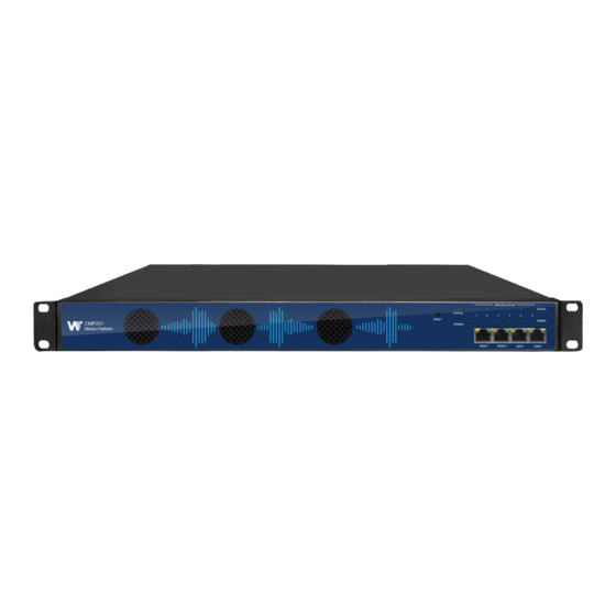
CMP201D User Guide 1 Chassis Overview 1.1 Front Panel CMP201D is a new generation of compact media platform which focuses on cost-effective commercial TV market and traditional DTV market. With powerful embedded Gigabit switch, optional commercial/broadcast level encoder modules and... -
Page 7: Back Panel
CMP201D User Guide 1.2 Back Panel CMP201D 6 hot-swappable modules Dual Power Supply III. Ground... -
Page 8: Installation
2 Installation 2.1 Rack Installation The CMP201D is designed to be mounted in a standard 19” rack. It takes 1RU of rack space. To install it into a rack, please use the following steps: Determine the desired position in the rack for the CMP201D. Make sure that the air intake on the top of the unit and the exhausts on the back of the unit will not be blocked. - Page 9 CMP201D User Guide When you take the equipment from a cold condition into a much warmer and humid c ondition, the equipment should be acclimated to the warm and humidity condition for at least 30 minutes. Powering up a non-acclimated unit may lead to shortcut or other damage to ele ctronic components.
-
Page 10: Module Overview
CMP201D User Guide 3 Module Overview 3.1 CMP201D Baseboard CMP201D Basic Function Baseboard 120 inputs & 120 outputs IP channel 3.2 Receiver Modules Module Description 4-channel DVBC receiving and descrambling CR2-DVBC-00 module with 1 RF female connector and 2 CI slots 4-channel DVB-S/S2 receiving and descrambling ... - Page 11 CMP201D User Guide 2-channel HDMI HD encoder, supports H. 264/MPEG-2 HD/SD, MPEG1L2, AAC (optional), AC3 (optional), supports CC subtitles CE2-HDMI-02 2-channel HDMI or component HD encoder, CE2-HDMI-02C supports H.264 / MPEG-2 HD/SD, MPEG1L2, AAC (optional), AC3 (optional), support CC subtitle and...
-
Page 12: Modulator Modules
CMP201D User Guide 3.4 Modulator Modules Module Description supports modulating 16 non-adjacent or channels with 1 RF female port for modulating output and 1 CM2-QAMA-R00 RJ45 network port is reserved for future use. CM2-QAMA-R01 / R01A supports modulating 4/8 adjacent channels with 1 ... - Page 13 CMP201D User Guide 3.5 Function Modules Module Description supports EAS triggerring by analogue EAS input CP2-EAS-00 and digital EAS input scrambling & descrambling module with 2 CI slots. It supports almost all kinds of CAM card descrambling and the number of descrambled CP2-CAM-00 services is defined by the CAM card.
-
Page 14: Web Gui
Set the IP address of the laptop/computer in the same network segment with the CMP201D Baseboard. CMP201D will occupy up to 7 IP addresses if it’s fully loaded as each module has its own IP address including the baseboard. -
Page 15: Login To The Web Gui
CMP201D User Guide CMP201D has an embedded gigabit switch inside the chassis. You can use it as a switch with other devices together. The four network ports are respectively used for managing and streaming. From left to right, port 1 and port 2 are used for management, port 3 and port 4 are used for data transmission.A good method of checking IP output is to play the IP streams using VLC player... -
Page 16: System Setting
CMP201D User Guide Device host operating status, running status of fans and other status display options Menu Bar and time display We use only IE, Firefox and Chrome for testing procedures. If you use other browsers, like Microsoft Edge, you may encounter incomplete UI layouts, and configure setting in these browsers may lead to errors. - Page 17 CMP201D User Guide System Setting> Network In Network page you can assign a static IP address to CMP201D’s baseboard. Click the Apply button on the right side to make the change take effect. Note to avoid IP conflict when you set the baseboard IP address. The occupied IP section will be displayed in this page on the top blue area.
- Page 18 CMP201D User Guide System Setting>System In System page you can do an upgrade, import or export configuration, import or export license (only for baseboard), reboot the whole unit, restore it to factory setting (only for baseboard), export log and clear log (only for baseboard).
-
Page 19: Ip Input
CMP201D User Guide 4.4 IP Input Click the IP Input on the top line to go into IP input page where you can see Status, Basic Setting and Service Configuration. IP Input >Status In this page, you can check each channel Total Bit Rate, Effect Bit Rate, TS Analysis and Service List. - Page 20 CMP201D User Guide Click Reset Counter button to clear continuity count errors and restart counting. Fill in the search bar with the key words of PID / Bit rate / bandwidth / table type / service name in the search bar to get the info you want.
- Page 21 CMP201D User Guide If you want to configure a batch of channels, please click “Batch Setting”. To set the IP input parameters in batch, you can check the boxes before parameters you need then choose/modify the values. Click Apply to make the setting take effect.
- Page 22 CMP201D User Guide IP Input >Service Configuration To stream an input source, you can configure the destination in this page. Multiplex or Bypass stream: Click the setting icon ( ), check the output module, and then you can set the output channel of this stream. After you select bypass mode, this output channel will be occupied only by this stream and when you set other stream output channels, this channel will not be available in this time.
-
Page 23: Ip Output
CMP201D User Guide After setting output destination, click Apply to make it take effect. The destination channel will be displayed in the channel/service line. And you can also click Clear Config to clear all of the configuration. There is a channel scan button ( ) on top. - Page 24 CMP201D User Guide IP Output >Settings Setting IP output channels is also similar to Setting IP input. Multicast output setting: You should fill the fit multicast IP addresses as output in the Destination IP Address box. Please avoid IP conflict among baseboard, encoder modules...
- Page 25 CMP201D User Guide Unicast output setting: You should fill the unicast receiving end’s IP addresses in the Destination IP Address box. Destination MAC: Normally you do not need to enable the Destination MAC switch. Only in some specific case where the unicast stream cannot be received due to unknown reasons, you can enable Destination MAC and fill in the correct receiver MAC in instead of using unicast IP addresses.
-
Page 26: Admin
CMP201D User Guide TS setting: Click TS line (the blue area) to configure Original Network ID, TS ID and each Service ID, Service Name, and Service Provider. NIT setting: Please refer to CM-QAM-00 module. 4.6 Admin Click Admin and you can choose to set the password or to log out. -
Page 27: Module Configuration
CMP201D User Guide 5 Module Configuration 5.1 Receiver Modules 5.1.1CR2-DVBC-00 CR2-DVBC-00 is a 4-channel DVBC/DTMB receiving and descrambling module with 1 RF female connector and 2 CI slots. It can receive 4 RF channels signal simultaneously and support 2 CAM cards descrambling. - Page 28 CMP201D User Guide Click the icon to check service information of all the inputs. You can check program details by clicking the program item.
- Page 29 CMP201D User Guide CR2-DVBC-00 >CI For the encrypted services received on CR2-DVBC-00 module receiver, CI slot is needed to decrypt and re-broadcast the services. The CR2-DVBC-00 has 2 CAM slots and can decrypt services depending on the capability of the CAM module and Smart Card. You can select the CAM Max Bit Rate from 48Mbps to 108Mbps in pull-down list depending on the total effective bitrate of services you want to decrypt at.
- Page 30 CMP201D User Guide Service Configuration page is where you can manage the received services and output them to their designated interface. The configuration of all modules in CMP201 is mostly the same. First, you need to scan the port on each LOCKED TS. Each port might be scanned automatically or needed to be scanned manually when its source is changed.
-
Page 31: Cr2-Dvbs2Ci-00
CMP201D User Guide On System page you can choose the modulation type as DVBC or DTMB Mode. Besides you can also perform Import/Export License, Reboot the module, Restore the unit to factory defaults and Log Export&Clear. 5.1.2 CR2-DVBS2CI-00 CR2-DVBS2CI-00 is a 4-channel DVB-S/S2 receiving and descrambling module with 2 RF... -
Page 32: Cr2-Dvbs2Fta-00/00A
CMP201D User Guide Service configuration is similar to CR2-DVBC-00. Status, CI Status and System operation refer to CR2-DVBC -00 module section. CR2-DVBS2CI-00 >Basic Setting Channel 1.1 and 1.2 share power with each other via LNB-1. Channel 2.1 and 2.2 share power via LNB-2. -
Page 33: Cr2-Dvbs2Fta-01
CMP201D User Guide CR2-DVBS2FTA-00A is the combination of 2 CR2-DVBS2FTA-00 modules. It is an 8-channel DVBS/S2 receiving module with 8 RF connectors, occupying 2 slots on the CMP201D chassis. 5.1.4 CR2-DVBS2FTA-01 CR2-DVBS2FTA-01 is a 4-channel DVB-S/S2/S2XFTA receiving module with 4 RF connectors, and 4 LNBs that are independently powered. - Page 34 CMP201D User Guide Click TS Analysis of each channel, you can see TS bit rate analysis. Click Reset Counter to reset the Continuity Count Error counter. In Search bar, you can input key words or numbers, such as PIDs, Type or service, for a quickly search.
- Page 35 CMP201D User Guide The absolute value of the difference between the Satellite Frequency and the LNB Frequency must be in the range [950, 2150]. Click the Apply button on the right side to make the changes made take effect. CR2-DVS2FTA-01 > Biss Here you can create Biss ID, including Mode, Key and Injected ID.
- Page 36 CMP201D User Guide Click Apply or Clear Config button on the right side to make the changes made take effect or clear all configuration. Scanning Time(ms): 1000~5000. Please try to increase this value if service name is not present, ...
- Page 37 CMP201D User Guide IP Output > Status> This page shows detailed status of each channel. The TS Analysis and Service List here have the same function to those on the Status page. See the image below for reference. IP Output > Settings > On this page, there are three tabs where you can modify the multicast IP, ports and parameters of IP Output.
- Page 38 CMP201D User Guide If you want to use IP output channels in the receiver module and baseboard IP output channel at the same time, you should avoid multicast IP addresses conflicts. If there are two identical IP addresses enabled concurrently, both the multicast transport streams will be affected.
- Page 39 CMP201D User Guide TS setting: Click TS line (the blue area) to configure Original Network ID, TS ID and each Service ID, Service Name, and Service Provider, etc. NIT setting: Click the icon to modiify NIT Network and NIT Stream.
- Page 40 CMP201D User Guide Log Manage> This page shows the logs of the module. If there are issues encountered on this module, exporting the logs will help R&D team to analyze and fix them. Turn on Enable Real-time Log switch, see the real time log messages and the security level of each message below.
-
Page 41: Cr2-8Vsb-00
CMP201D User Guide 5.1.5 CR2-8VSB-00 CR2-8VSB-00 is a 4-channel 8VSB receiving module with 4 RF connectors. 8VSB receiver is mainly adopted on ATSC standard. CR2-8VSB-00 >Status CR2-8VSB-R01/R01A >Basic Setting 4 -channels receiving is supported with 4 connectors. All the CHs at specific frequency points are displayed when you select the fixed Channel Standard. -
Page 42: Cr2-Dvbt2-00
CMP201D User Guide Channel standard Off-Air CH2-57MHz, CH3-63MHz, CH4-69MHz~ CH67-791MHz, CH68-797MHz, CH69-803MHz CH2-57MHz, CH3-63MHz, CH4-69MHz~ CH133-849MHz,CH134-855MHz, CH135-861MHz CH2-57MHz, CH3-63MHz, CH4-69MHz~ CH133-849MHz,CH134-855MHz, CH135-861MHz CH2-55.75MHz, CH3-61.75MHz, CH4-67.75MHz~ CH133-847.75MHz,CH134-853.75MHz, CH135-859.75MHz Status, Service Configuration and System is similar to CR2-DVBC-00. 5.1.5 CR2-DVBT2-00 CR2-DVBT2-00 is a 4-channel DVB-T/T2 receiving and descrambling module with 1 RF connectors and 2 CI slots. -
Page 43: Encoder Modules
CMP201D User Guide Name Range Frequency (KHz) 47000~862000 Bandwidth (Mbps) 6 / 7 / 8 M Click the Apply button on the right side to make the change take effect. Status, CI, Service Configuration and System please refer to CR2-DVBC-00. - Page 44 CMP201D User Guide CE2-HDMI-00/R01 >Status CE2-HDMI-00/R01 >Basic Setting Click Advanced Setting to see all parameters you can modify and check what specific parameters you want to set and see. Click the Apply button on the right side to make the change take effect.
- Page 45 CMP201D User Guide Setting range: Video Encode Range Video Encode Range Settings Settings Video Type H264 , MPEG2 GOP Close Disable, Enable Video Bitrate (Kbps) 600~20000 PCR2 PID 32~8190 Video Mode CBR, VBR PMT PID 32~8190 Video Max Bitrate (K...
- Page 46 CMP201D User Guide 4x3_CutOff GOP Size 6~63 Audio Encode Settings Range Audio Encode Settings Range Encoding Type Audio Sampling Bitrate (KHz) MPEG1_Layer2 MPEG2_AAC MPEG4_AAC Audio Mode Dual Channel Audio PID 32~8190 Mono Stereo Encoding Bitrate(Kbps) 128~384 (AC3) Volume 64~384(MPEG1_Layer2) 32~384(MPEG2_AAC/ MPEG4_AAC) CE2-HDMI-R01 >Basic Setting...
- Page 47 CMP201D User Guide GOP Size PMT PID 1~99 32~8190 Video Resolution Auto , 1920×1080_60i , Program Name Length is 1~16 1920×1080_50i , 1920×1080_30p , 1920×1080_25p , 1080×720_60p 1080×720_50p , 720×480_60i , 720×576_50i Profile HIGH Provider Name Length is 1~16 MAIN...
- Page 48 CMP201D User Guide For the Output, both models have direct IP output and multiplexing, but only CE2-HDMI-R01 has RTMP output settings. This feature is specifically for single program encoding and IP output directly. Outputting in this way will not occupied baseboard multicast bandwidth.
- Page 49 CMP201D User Guide To use Multiplexing mode on service level 1. Click on the pencil icon . There will always be a BaseBoard selection for the IP output and other Output options depending on the modules inserted. 2. Select the correct Output and Channel you want to output the Service to.
- Page 50 CMP201D User Guide LOGO setting: you can upload several pictures at the same time, and pick one to show on the screen. The feild of the selected picture will turn green. LOGO Parameter LOGO Parameter Range Range Position X...
- Page 51 CMP201D User Guide Subtitle Parameter Range LOGO Parameter Range Position Bottom/Top/Middle Position Offset -200~200 Horizontal Pixel 10~1920 Scrolling Speed 1~20 Front Color White/Black/Blue/Green/ Front Size 0~100 Red/Yellow Display Interval 0~100 QR Code setting: QR Code picture picking method is same as LOGO setting.
-
Page 52: Ce2-Hdmi-02
CMP201D User Guide LOGO Parameter Range LOGO Parameter Range Position X Position Y 0~1920 (Dual) 0~1080 (Dual) Size width Size Height 0~1920 (Dual) 0~1080 (Dual) CE2-HDMI-00/R01 > System Please refer to CR2-DVBC module. 5.2.2 CE2-HDMI-02 CE2-HDMI-02 is a 2-channel HDMI encoder which supports H.264 HD/SD or MPEG-2 HD/SD encoding with 2-channel RCA for CC input. - Page 53 CMP201D User Guide CE2-HDMI-02 >Status CE2-HDMI-02 >Basic Setting Click Basic Parameters then click Advanced Setting to see Video Parameters & Audio Parameters & Service Parameters that you can modify and check what specific parameters you want to see and set. Click the Apply button on the right side to make the change take effect.
- Page 54 CMP201D User Guide Setting Range: Video Encode Range Video Encode Range Settings Settings Video Type H264 , MPEG2 GOP Size 18~48 Video Bitrate (Kbps) 2000~18000 PCR2 PID 32~8190 Video Mode PMT PID 32~8190 Video Max Bitrate 18000 Service Name Length is 1~16...
- Page 55 CMP201D User Guide Audio Bitrate(Kbps) Audio PID 128~384 (AC3) 32~8190 64~384(MPEG1_Layer2/ MPEG2_AAC/ MPEG4_AAC/ AC3 Passthrough) 32~384(AAC_HE_V2) Click Advance Parameters to set Encoding Parameters & Stream Output Parameters & MPEG-2 Output Parameters & MPEG4/MPEG4_AVC Output Parameters &Other Parameters for CH1.1/CH2.1 separately.
- Page 56 CMP201D User Guide Enable Destination MAC: Generally, you do not need to enable this option. This is reserved for exceptional cases where the unicast stream cannot be received with unicast IP addresses. You can enable destination MAC and streaming out by setting Destination MAC.
- Page 57 CMP201D User Guide 5.2.3 CE2-HDMI-02C CE2-HDMI-02C is a 2-channel HDMI or component HD encoder. It supports H.264 / MPEG-2 HD/SD, MPEG1L2, AAC (optional), AC3 (optional) audio, CC subtitle and analog audio input. CE2-HDMI-02C>Status CE2-HDMI-02C>Basic Setting Click Basic Parameters then click All Configurable Parameters to see Video Parameters &...
- Page 58 CMP201D User Guide Setting Range: Video Encode Range Name Range Settings Input TS Source HDMI, Component Video Type H264 , MPEG2 GOP Size 18~48 Video Bitrate (Kbps) 2000~18000 PCR2 PID 32~8190 Video Mode PMT PID 32~8190 Video Max Bitrate 18000...
- Page 59 CMP201D User Guide AC3_Passthrough 32~384(AAC_HE_V2) Audio AAC Format MPEG1_Layer2 ADTS MPEG2_AAC LATM MPEG4_AAC AAC_HE_V2 Audio PID 32~8190 Volume Click Advance Parameters Encoding Parameters & Stream Output Parameters & MPEG-2 to set Output Parameters & MPEG4/MPEG4_AVC Output Parameters &Other Parameters for CH1.1/CH2.1 separately.
- Page 60 CMP201D User Guide This feature is specifically for single program encoding and IP output directly. Outputting in this way will not occupy baseboard multicast bandwidth. If you want to use IP output channels in the encoder module and baseboard TSoIP module at same time, you should avoid a multicast IP address conflict.
-
Page 61: Ce2-Sdi-00
CMP201D User Guide it is triggered by external IP or analogue signal, the services(s) will be switched to the AV or ASI service from EAS module. Service: There are 2 programs corresponding to 2 HDMI/Component ports Status: Paved/Unpaved ... - Page 62 CMP201D User Guide CE2-SDI-00>Status Status page for CE2-SDI-00 shows the following parameters: Signal Status, Input Video Resolution, Output Video Resolution, Video Bitrate, Audio Bitrate, Audio2 Bitrate, Total Bitrate, Effective Bitrate, TS anaylsis and Program Name. The following parameters will display values once a good SDI source is connected.
- Page 63 CMP201D User Guide Setting Range: Video Encode Range Video Encode Range Settings Settings Input Source Type CVBS, SDI GOP Size 18~48 Video Type H264 , MPEG2 PCR2 PID 32~8190 Video Bit Rate (Kbp PMT PID 2000~18000 32~8190 Video Mode Program Name...
- Page 64 CMP201D User Guide Click Advance Parameters to set Encoding Parameters & Stream Output Parameters & MPEG-2 Output Parameters & MPEG4/MPEG4_AVC Output Parameters & Other Parameters for CH1.1/CH2.1 separately. CE2-SDI-00>Output This feature is specifically for single program encoding and IP output directly. Outputting in this way will not occupied baseboard multicast bandwidth.
-
Page 65: Ce2-Cvbs-00/R01/R01A
CMP201D User Guide The parameters of EAS Source Multicast Address & Command Port & Data Port should be consistent with CP2-EAS-00 module. Then the EAS module will be detected automatically by CE2-SDI-00 module so that the service(s) could be paved by EAS input(ASI or AV signal). When it is triggered by external IP or analogue signal, the services(s) will be switched to the AV or ASI service from EAS module. - Page 66 CMP201D User Guide CE2-CVBS-00/R01(6/8 CH) CE2-CVBS-R01A(16 CH) Configuration is similar to CE2-HDMI module. Please refer to that module section. CE2-CVBS-00 >Settings Click Advanced Setting to see all parameters you can modify and check what specific parameters you want to set and see. Click the Apply button on the right side to make the change take effect.
- Page 67 CMP201D User Guide Setting range: Video Encode Range Video Encode Range Settings Settings Video Type Service Name H264 , MPEG2 Length is 1~16 Video Bitrate (Kbps) Service Provider 600~20000 Length is 1~16 Name Video Mode Brightness CBR, VBR 0~255 Video Max Bitrate...
- Page 68 CMP201D User Guide Encoding Type Audio Sampling MPEG1_Layer2 Bitrate(KHz) Audio Mode (AC3) Audio PID Dual Channel/Mono/ 32~8190 Stereo Encoding Bitrate(Kbps) Volume Setting 64~384 0.00~8.00 CE2-CVBS-R01 /R01A>Settings CE2-CVBS-R01 module has 8 channels with 2 DB15 connectors and CE2-CVBS-R01A module has 16 channels with 4 DB15 connectors. The configuration of them are similar to CE2-CVBS-00, there are a few differences on parameter setting range.
-
Page 69: Ce2-Hdmi-05/05A
CMP201D User Guide Audio Encoder Details Range Audio Encoder Details Range Encoding Type Audio Sampling Bit MPEG1_Layer2/AAC/AC3 rate(KHz) Audio Mode (AC3) Audio PID Stereo 32~8190 Encoding Bitrate(Kbps) 32~192 Volume (dB) -20~20 Delay (ms) -2000~2000 CE2-CVBS-00/R01/R01A > Output/ Insertion Output and Insertion please refer to CE2-HDMI-R01 module. - Page 70 CMP201D User Guide CE2-HDMI-05A >Status CE2-HDMI-05A >Basic Setting This page allows you to modify the Video, Audio and Service Parameters. Click Advanced Setting to see all parameters you can modify and check what specific parameters you want to set and see.
- Page 71 CMP201D User Guide Name Range Name Range Video Type H.264 , H.265 Video PID 32~8190 Video Bitrate (Kbps) PCR2 PID 600~12000 32~8190 GOP Size 1~60 PMT PID 32~8190 Video Resolution Program Name Auto , Length is 1~31 Manual(Horizontal Pixels: 160~1920, Vertical Pixels:...
- Page 72 CMP201D User Guide This feature is specifically for single program encoding and IP output directly. Outputting in this way will not occupy baseboard multicast bandwidth. If you want to use IP output channel in the encoder module and baseboard IP Output module at same time, you should avoid the multicast IP address conflict.
- Page 73 CMP201D User Guide LOGO setting: you can upload several pictures at the same time, and pick one to show on the screen The field of the selected picture will turn green. LOGO Parameter Range LOGO Parameter Range...
- Page 74 CMP201D User Guide Position X Position Y 0~1920 (Dual) 0~1080 (Dual) Size width Size Height 2~1920 (Dual) 2~1080 (Dual) OSD setting: Subtitle Parameter Range LOGO Parameter Range Position Bottom/Top/Middle Position Offset -200~200 Horizontal Pixel 10~1920 Scrolling Speed 1~20 Front Color...
- Page 75 CMP201D User Guide QR Code Parameter Range QR Code Parameter Range Position X 0~1920 (Dual) Position Y 0~1080 (Dual) Size width 0~1920 (Dual) Size Height 0~1080 (Dual) CE2-HDMI-05A >Output Output configuration please refer to CR2-DVBC module. CE2-HDMI-05A > System...
-
Page 76: Ce2-Hdmi-06
CMP201D User Guide On System page you can Import/Export License, Reboot module, Reset to Dafaults and Manage Logs. 5.2.7 CE2-HDMI-06 CE2-HDMI-06 is a 4-channel HDMI encoder (broadcast level). It supports H.264/H.265 HD/SD encoding(up to 1080p60), B frame, de-interlacing. Audio encoding of MPEG1-L2, AAC (optional) and AC3 (optional). - Page 77 CMP201D User Guide This page allows you to modify the Video, Audio and Service Parameters. Click Advanced Setting to see all parameters you can modify and check what specific parameters you want to see and set. Click the Apply button on the right side to make the change take effect.
- Page 78 CMP201D User Guide 96~192 (AC3) Volume(dB) Audio PID -20~20 32~8190 Shelter Parameters Range Shelter Parameters Range Shelter Enable/Disable 0~1920 (Dual) 0~1080 (Dual) Width 2~1920 (Dual) Height 2~1080 (Dual) Color White/Black/Blue/Green/Red CE2-HDMI-06 >Output This feature is specifically for single program encoding and IP output directly. Outputting this way will not occupy baseboard multicast bandwidth.
- Page 79 CMP201D User Guide To use Multiplexing mode at service level: 1. Click on (pencil) icon. There will always be a BaseBoard selection for the IP output and other Output options depending on the module inserted. 2. Select the correct Output and Channel you want to output the service to.
- Page 80 CMP201D User Guide LOGO Parameter Range LOGO Parameter Range Position X 0~1920 (Dual) Position Y 0~1080 (Dual) Size width 2~1920 (Dual) Size Height 2~1080 (Dual) OSD setting: ...
- Page 81 CMP201D User Guide Subtitle Parameter Range LOGO Parameter Range Horizontal Pixel 10~1920 Scrolling Speed 1~20 Front Color White/Black/Blue/Green/ Front Size 0~100 Red/Yellow QR Code setting: QR Code picture picking method is same as LOGO setting. ...
- Page 82 CMP201D User Guide QR Code Parameter Range QR Code Parameter Range Position X 0~1920 (Dual) Position Y 0~1080 (Dual) Size width 0~1920 (Dual) Size Height 0~1080 (Dual) CE2-HDMI-06 > System...
-
Page 83: Modulation Output Modules
CMP201D User Guide On the System page you can Import/Export License, Reboot module, Reset to Dafaults and Manage Logs. 5.3 Modulation Output modules 5.3.1 CM2-QAMA-R00/R01/R01A CM2-QAMA-R00 CM2-QAMA-R00 module supports modulating 16 non-adjacent or channels with 1 RF female port for modulating output and 1 RJ45 network port is reserved for future use. - Page 84 CMP201D User Guide Click the Apply button on the right side to make the change take effect. Name Range Name Range Bandwidth 6M, 7M, 8M RF level 0~63 (dBμV) 60~123 (dBmV) Symbol Rate (KBaud) 4400~6956 Frequency (KHz) 48000~858000 PSI/SI Interval (ms)
- Page 85 CMP201D User Guide Click +Descriptor and add the Cable Descriptor in. Then fill in the correct frequency and symbol rate and choose the correct constellation of the TS (frequency). Then click OK. (this operation should be set on Modulator module only).
- Page 86 CMP201D User Guide CM2-QAMA-R01>Basic Setting Click the Apply button on the right side to make the change take effect. Name Range Name Range Symbol Rate (KBaud) 3780~5217 PSI/SI Interval (ms) 50~10000 RF level Frequency (KHz) 48000~862000 25~45dBmV/85~105dBμV QAM Mode QAM16/32/64/128/256 CM2-QAMA- R01/R01A>Output...
- Page 87 CMP201D User Guide LCN setting: You need to add NIT streams of all frequencies in the base TS (frequency), which is used for your STB to automatically search and identify all the TS (frequencies) LCN information. Check or reset Original Network ID and TS ID of each TS (frequency). Each TS should have ...
-
Page 88: Cm2-8Vsb-R01/R01A
CMP201D User Guide Repeat the operations to add next TS (frequency) until NIT streams of all the frequencies have been included. Finally click Apply to let all configuration take effect. Then searching programs in your STB, you will get all programs in the order of LCN you set. -
Page 89: Cm2-Qamb-R00/R01/R01A
CMP201D User Guide Channel Standard OFF-AIR Frequency (KHz) CH2-57MHz CH69-802MHz CM2-8VSB-R01/R01A >Output TS setting: Please refer to IP output service configuration. To use this board, you need to change the Standard to ATSC in Advance Settings-System Settings. Don’t forget to click APPLY when you finish configuration. - Page 90 CMP201D User Guide Module configuration is similar to IP Setting. CM2-QAMB-00 >Basic Setting Click the Apply button on the right side to make the change take effect. Name Range Name Range Bandwidth (MHz) Channel Standard STD/IRC/HRC Symbol Rate (KBaud) 5056.941 (QAM 64) RF level 75~105 (dBμV)
- Page 91 CMP201D User Guide CM2-QAMB-R01/R01A CM2-QAMB-R01 / R01A module supports up to 4/8 adjacent frequencies modulating with 1 RF female connector for output. Module configuration is similar to IP Setting. CM2-QAMB-R01/R01A>Basic Setting Click the Apply button on the right side to make the change take effect.
- Page 92 CMP201D User Guide TS setting: Please refer to IP output service configuration. LCN setting: You need to add NIT streams of all frequencies to the base TS (frequency), which is for your STB to automatically search and identify all the TS (frequencies) LCN information.
-
Page 93: Cm2-Ofdm-R01/R01A
CMP201D User Guide Repeat the operations to add next TS (frequency) until NIT streams of all the frequencies have been included. Finally click Apply button to let all configuration take effect. Then searching programs in your STB, you will get all programs in the order of LCN which you set. - Page 94 CMP201D User Guide CM2-OFDM-R01A>Output TS setting: Please refer to IP output configuration. LCN setting: You need to add NIT stream of all frequencies in the base TS (frequency) which is used for your STB auto search and identifies all the TS (frequencies) LCN information.
-
Page 95: 5Cm2-Isdbt-R01/R01A
CMP201D User Guide Repeat the operations to add next TS (frequency) until NIT streams of all the frequencies have been included. Finally click Apply button to let all configuration take effect. Then searching programs in your STB, you will get all programs in the order of LCN which you set. - Page 96 CMP201D User Guide GI Mode 1/4, 1/8, 1/16, 1/32 RF Level Gain(dB) 45~55 QAM Mode QPSK Convolutional 1/2, 2/3, 3/4, 5/6, 7/8 16QAM Coding 64QAM CM2-ISDBT-R01/R01A>Output TS setting: Please refer to IP output service configuration. LCN setting: You need to add NIT streams of all frequencies to the base TS (frequency) which is ...
-
Page 97: Cm2-Mod-02
CMP201D User Guide Repeat the operations to add next TS (frequency) until NIT streams of all the frequencies have been included. Finally click Apply button to let all configuration take effect. Then searching programs in your STB, you will get all programs in the order of LCN you set. - Page 98 CMP201D User Guide CM2-MOD-02 > Status The Status page contains status information of IP Input, Modulation Output and IP Output. IP Input > CM2-MOD-02 has 1024 IP input channels. Those channels are divided into two RJ45 ports, each port has 512 IP input channels. Click Port 1 tab, users can obtain the 256 channels status information such as input source IP address and port number, total bitrate (Mbps) and effective bitrate (Mbps).
- Page 99 CMP201D User Guide Click the eye icon , users can know all the PIDs such as PAT, CAT, PCR2, Video Audio, PCR2 PID etc in this TS. See the image below for reference. If the input stream has multiple programs, users can click the icon below “Service List” to see all the...
- Page 100 CMP201D User Guide You can also check the details of a service by clicking the Service Name. Modulation Output > CM2-MOD-02 status shows the Modulation output. Just like the IP Input, this shows the total bitrate and effective bitrate of the 32 channels respectively. The TS Analysis and Service List have the same function as in the IP input.
- Page 101 CMP201D User Guide IP Output > CM2-MOD-02 status also shows the IP output. Just like the IP Input, this shows the total bitrate and effective bitrate of the 16 channels respectively. The TS Analysis and Service List have the same function as in the IP input. See image below for reference.
- Page 102 CMP201D User Guide CM2-MOD-02 > Basic Setting CM2-MOD-02 Basic Setting is where users input the parameters for IP Input, Modulation Output and IP Output. IP Input-Parameter Setting> On this page, there are three tabs where you can modify the multicast IP, port and parameter of IP Input.
- Page 103 CMP201D User Guide Batch Setting is where users can input the IP input parameters in batch. See the image below for reference. Modulation Output-Parameter Setting> On this page, you can enable channels as you need and input the Frequency (KHz), QAM Mode, Symbol Rate (KBaud) and RF Level Gain (dBmV) to have an...
- Page 104 CMP201D User Guide Here is the range parameter of the above info. Parameters Range Frequency(KHz) 47000 ~ 999000 QAM Mode QAM16, QAM32, QAM64, QAM128, QAM256 Symbol Rate(KBaud) 3600 and 6952 -10 ~ 0 RF Level Gain (dBmV) (The value must be a number multiple of 0.5)
- Page 105 CMP201D User Guide Batch Setting is where you can input the modulation parameters in batch. See the image below for reference. IP Output-Parameter Setting> On this page, there are three tabs where you can modify the multicast IP, port and parameter of IP Output. There are Port 1, Port 2 and Batch Setting. The output can accept Multicast or Unicast and support MPTS and SPTS.
- Page 106 CMP201D User Guide Batch Setting is where you can input the IP output parameters in batch. See the image below for reference. CM2-MOD-02 > Multiplexing Multiplexing has four tabs: Source, Service Configuration, SI Table Setting and PID Transmission. Here you are can set to output services from IP Input to Modulation Output. Click...
- Page 107 CMP201D User Guide Multiplexing to see 32 modulation output channels. Select a channel you want to configure and you will see Source setting of this channel. Multiplexing-Source> Source is where you select a source for output. You can chose Port 1 or Port 2 for the source.
- Page 108 CMP201D User Guide To Output the TS by Bypass mode, you can simply check the Bypass box of the TS. You can only bypass 1 TS and cannot output other services from different channel sources. Bypass mode allows you to keep the input signal automatically be redirected to Modulation output without re-scanning the input or transferring it to output.
- Page 109 CMP201D User Guide Here you can also edit the Original Network ID and TS ID of the Modulation Output. Here you can also edit NIT and create NIT Network for the OTA upgrade. Still in NIT, you can also create NIT Streams and generate LCN for channel list and Cable Descriptor...
- Page 110 CMP201D User Guide For the LCN Descriptor: input the Service ID and the LCN for the channel line-up of the services. For the Cable Descriptor: input the correct frequency and SymbolRate for the corresponding TS output. Cable descriptor depends on the setup you use. Mostly, Cable descriptor is created for 1 TS only.
- Page 111 CMP201D User Guide Multiplexing-SI Table Setting> This page is to choose whether to insert/generate the SI tables or Copy the SI tables from the input streams. Multiplexing-PID Transmission> This page is to transmit the input PID to Output on the PID required by the system.
- Page 112 CMP201D User Guide Service Scrambling> On this page, you can encrypt a service in the Modulation Output. Select a channel for output and you will see a service list. The module supports up to 6 different CA, select one of them for encryption as you need, then select the CA ID of the service. Click Apply to finish setting.
- Page 113 CMP201D User Guide CM2-MOD-02 > System CM2-MOD-02 System is composed of two sub menus namely Network and License. Network> Here you can modify the IP Address, Subnet Mask and Gateway for each port of the module, except for the address of the module itself. This also shows the MAC Address of each port of the module.
- Page 114 CMP201D User Guide Log Manage> This page shows the logs of the module. If there are issues encountered on this module, exporting the logs will help R&D team to analyze and fix them. Turn on Enable Real-time Log switch to see the real time log messages and the severity level of each message below.
-
Page 115: Function Modules
CP2-EAS-00 module provides the ability to interrupt Encoder playback and switch to an external transport stream. This feature is for the US market and requires the CMP201D chassis to be set for ATSC standard. A common application of Emergency Alert Systems is for Broadcast and Audio Muting. - Page 116 CMP201D User Guide CP2-EAS-00>Basic Setting...
- Page 117 CMP201D User Guide Click the Apply button on the right side to make the change take effect. Name Range Name Range Command Input Setting EAS Signal Input Digital(IP) EAS Program Input Analogue(Dry Contact) Analogue(Relay) Trigger Mode Normally Open Normally Closed...
-
Page 118: Cp2-Cam-00
CMP201D User Guide 5.4.2 CP2-CAM-00 CP2-CAM-00 is a scrambling & descrambling module with 2 CI slots. It supports almost all kinds of CAM card descrambling and the number of descrambled services is defined by the CAM card. supports descrambling services which are multiplexed from different IP/RF channels or modules. - Page 119 CMP201D User Guide CP2-CAM-00 >Status Status shows the total bitrate and effective bitrate of each channel. It also supports TS analysis and service list. Click the icon ( ) below the TS Analysis to see the TS analyzing result of this channel. Click the icon ( ) below the Service List to see the Services of this channel.
- Page 120 CMP201D User Guide CP2-CAM-00 >CI CI page not only shows the CAM card name and CA system ID, but also shows the service PID, service information and scrambling/descrambling status. CAM Max Bitrate is from 48Mbps to 108Mbps, which you can choose in the pull-down list.
- Page 121 CMP201D User Guide Click Reset to reboot the CAM card. Click Apply on the right side to make the change take effect. CP2-CAM-00 >Service Configuration When this module is licensed to scramble, on this page, you can set the output destination of all services.
- Page 122 CMP201D User Guide When this module is licensed to scramble, it has the functions of scrambling and descrambling. Change the CAM Mode through pull-down list. Click Apply to save the change. When this module is licensed to descramble, it only can be served as descrambling.
- Page 123 CMP201D User Guide Click to clear all log messages on the screen. Click to delete all log information. Click to export log information. Click to filter desired log message. ...
-
Page 124: Cp2-Eit-00
CMP201D User Guide 5.4.3 CP2-EIT-00 CP2-EIT-00 is an EIT multiplex module. It supports up to 32 TS inputs and up to 16 TS outputs. It also supports EIT multiplexing enable control at module level, TS level and program level. Multiple EIT multiplexing modules can run simultaneously in a single chassis. - Page 125 CMP201D User Guide Here you can select all modules or click checkbox of the module option which you need to make EIT enabled configuration. EIT function is enabled by default on modulator module and disabled on all IP output channels of baseboard. You can check the detailed information in the Tips tab.
- Page 126 CMP201D User Guide After finish the service configuration, you can go to the EIT module to enable or disable the EIT multiplexing for specific services and check the EIT multiplexing status. EIT function is enabled on modulation module and disabled on IP output of baseboard by default.
- Page 127 CMP201D User Guide On System page you can import/export license, reboot module, restore factory default setting s and manage logs for trouble-shooting. Log Manage> This page shows the logs of the module. If there are issues encountered on this module, exporting the logs will help R&D team to analyze and fix them.
- Page 128 CMP201D User Guide Clicking the filter icon, you can simply select what logs to be included.
-
Page 129: Appendices
CMP201D User Guide 6 Appendices Appendix A – Abbreviations 8VSB Vestigial sideband modulation with 8 discrete amplitude levels 16VSB Vestigial sideband modulation with 16 discrete amplitude levels Advanced Audio Coding AC-3 Also known as Dolby Digital Asynchronous Serial Interface ATSC... - Page 130 CMP201D User Guide Group of Pictures High Definition HDCP High-bandwidth Digital Content Protection HDMI High Definition Multimedia Interface Input/output Kbps 1000 bit per second Logical Channel Number Low-Noise Block Local Oscillator Mbps 1,000,000 bits per second Modulation Error Ratio Management Information Base...
-
Page 131: Appendix B- Warranty
Please contact our sales/regional representatives for any help, product information, and troubleshooting. Returning Products for Service The CMP201D is a delicate piece of equipment and needs to be serviced and repaired by the manufacturer. In order to expedite this process please carefully read the following items. Confirm the required component ...
Need help?
Do you have a question about the CMP201D and is the answer not in the manual?
Questions and answers