Advertisement
Quick Links
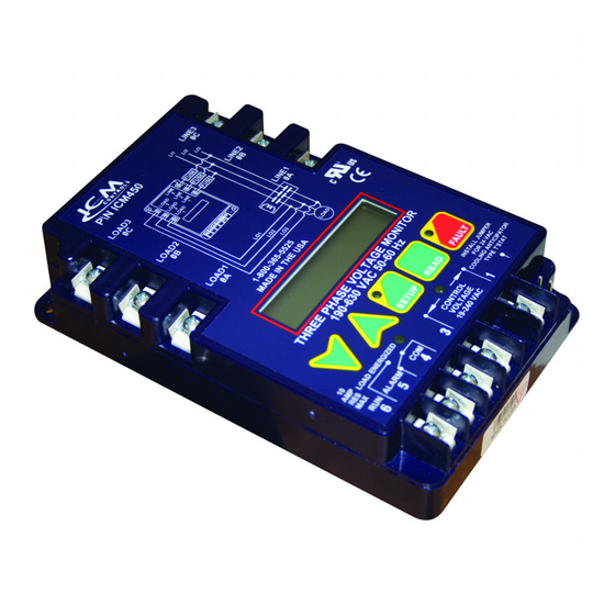
ICM450A &
ICM450A plus+
Programmable 3-Phase
Line Voltage Monitors
Specification
Input:
• Line Voltage: Universal, 190-600 VAC
• Frequency: 50-60 Hz
• Load Side Monitoring: Optional
• Control Voltage: 18-240 VAC
• Frequency: 50-60 Hz
Output:
• Type: Relay, SPDT
• Voltage Range: 277 VAC @ 10A maximum
• Frequency: 50-60 Hz
Control Operating Temperature
• Operating Temperature: -40ºF to +167ºF (-40ºC to +75ºC)
• Storage Temperature: -40ºF to +185ºF (-40ºC to +80ºC)
LCD Operating Temperature : -4ºF to +167ºF (-20ºC to +75ºC)
Mechanical:
• Mounting: Surface mount using (2) #8 screws
• Terminations: 1/4" quick connects
• Weight: 12 ounces (341 grams)
ModBus: RS485 Communication (ICM450A plus+)
Dimensions: 6.5"L x 4.75"W x 1.09"D
Parameters
Line Voltage: Universal 190-600 VAC
Phase Unbalance Protection
• Voltage Unbalance: 2-20% adjustable
Over/Under Voltage Protection
• Under Voltage: 2-25% adjustable
• Over Voltage: 2-25% adjustable
Phase Loss Protection
• Phase Loss Condition: Equals 25% of nominal for any given phase; system will shut
down and a fault will be recorded should this occur
Delay on Break Timer
• Time Delay: 0 to 10 minutes adjustable
Control Voltage: 18-240 VAC
• Control Mode: ON/OFF
Fault Interrogation Delay
• Time Delay: 0 to 15 seconds adjustable
• Provides a delay between fault detection and system shutdown - helps to eliminate
nuisance trips or unnecessary shutdowns
Reset Mode: 0 (auto) or 1-10 retries
Set Date and Time: Provides real time clock for date and time stamp (ICM450A plus+)
Language: Set to English or Spanish language for display
Installation of the ICM450A and ICM450A plus+ shall be performed by trained
technicians only. Adhere to all local and national electric codes.
Disconnect all power to the system before making any connections.
Caution
Installation
1. Using (2) #8 screws, mount the ICM450A and ICM450A plus+ in a cool, dry, easily
accessible location in the control panel.
2. Connect voltage as shown in Figure 1 (below). Leave existing line and load side
connections intact on the contactor.
3. Load side monitoring is optional (unit may be used to monitor line side only). Wire the
contactor and optional control voltage monitoring as in Figures 2 and 3 (below).
Note: Load/line wire must be rated for 3-phase voltage rating, 20 AWG minimum.
4. Upon application of power, the CM450A and ICM450A plus+ will be on line and will
begin to monitor the system.
Figure 1
Incoming 3-phase
voltage from load
or "back" side of
contactor (optional)
• Terminals 4 and 5 are the control signal input terminals
• "Control Mode" is turned ON or OFF in setup
• With "Control Mode" set to "ON," there must be a voltage present on terminals 4 and
5 for the relay output terminals 1 and 2 to close; this voltage can be supplied from a
thermostat, pressure switch, etc.
• When the voltage on these terminals is re-applied,
the unit will not re-energize until the delay on break
(0-10 minutes) time has elapsed
• Use of terminals 4 and 5 is optional; they will be ignored if the "Control Mode" is
set to "OFF"
• Terminals 1 and 2 are "dry," normally open contacts
• Terminals 1 and 2 are closed when power is within specifications
• Terminals 1 and 2 open when there is a fault condition
• Terminals 1 and 2 open when there is a loss of the control signal with "Control Mode" set
to "ON"
Note: Terminals 6, 7 and 8 used for ModBus communication on ICM450A and
ICM450A plus+.
Figure 2
COM NO NC
Contactor
Coil
Contactor Voltage
(18-240 VAC)
Optional Control Voltage
ICM450A and ICM450A plus+ Wiring Diagrams
2-Pole Contactor
Load
L1 L2
3
1
2
3
4
5
6
7
8
Optional Control
Voltage
18-240 VAC
Load 1
Load 2
LOAD
Setting the Parameters
1. Press the SETUP button to enter Setup mode. Setup LED will light.
2. Use the
and
arrows to change user parameters.
3. Scroll through setup by pressing and releasing the SETUP button.
4. When the last parameter has been set, the phase average will be displayed and the
Setup LED will automatically turn OFF.
Button Functions
Press arrows to scroll
Press to
through and select user
enter Setup
parameter settings in
mode and
Setup mode. HOLD
select user
down for fast edit.
parameters.
Incoming 3-phase voltage from
line or "front" side of contactor
The incoming 3-phase voltage
is used to power up the
ICM450A as well (190-600)
Figure 3
COM NO NC
Contactor
Coil
Contactor Voltage
(18-240 VAC)
Optional Control Voltage
3-Pole Contactor
L3
1
2
3
4
5
6
7
8
Optional Control
Voltage
18-240 VAC
Load 1
Load 2
Load 3
Hold for
Press to read
voltage display
faults. Hold for 5
a
b, b
c,
seconds to clear
a
c
faults and reset
(simultaneously).
L1 L2
L3
LOAD
memory.
Advertisement

Related Manuals for ICM Controls ICM450A


Summary of Contents for ICM Controls ICM450A
- Page 1 ICM450A & Installation 1. Using (2) #8 screws, mount the ICM450A and ICM450A plus+ in a cool, dry, easily accessible location in the control panel. ICM450A plus+ 2. Connect voltage as shown in Figure 1 (below). Leave existing line and load side connections intact on the contactor.
- Page 2 ON or OFF Based on wiring the load will energize if no fault conditions exist and control voltage is present at terminals 4 and 5 of the ICM450A Date and Time Provides real time clock for date and time stamp (ICM450A plus+ models)