Scheer MH Series Installation And Maintenance Instructions Manual
Hide thumbs
Also See for MH Series:
- Installation and maintenance manual (42 pages) ,
- User manual (18 pages)

Related Manuals for Scheer MH Series


Summary of Contents for Scheer MH Series
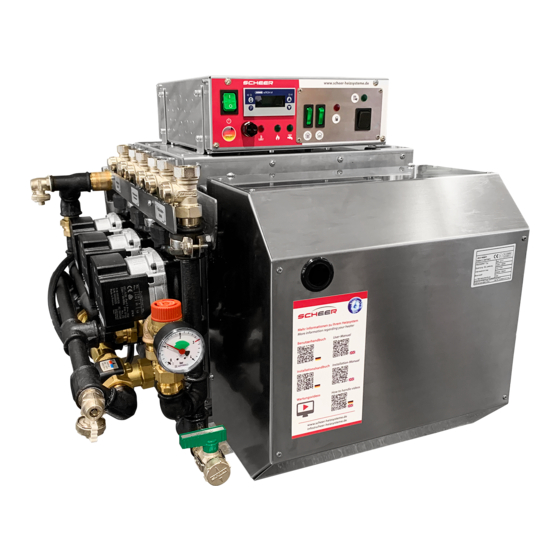
- Page 1 MH series water heater MH 10 micro MH 10/17 MH 15/23 MH 20 micro L MH 30/40 Installation and maintenance instructions...
- Page 2 Fax: + 49 (0) 4839 453 info@scheer-heizsysteme.de www.scheer-heizsysteme.de Note: Always carefully follow SCHEER installation and repair instruction and heed all WARNINGS. SCHEER rejects any liability for defects and damage, which are due to installation or repair by unauthorized and untrained persons.
-
Page 3: Table Of Contents
Warning and safety instructions (explanation) Installation ..........................Initial commissioning ................................................Type plate ......................... Technical data ......................Structure of the MH series Control box A ................................................Heating controller ........................Interference lights ..................... Pipe connection groups (examples) Domestic hot water heating (optional) .................. -
Page 4: Legal Requirements
legal regulations governing installation 1.1. legal regulations governing installation. The heaters of the MH-series are type-tested and approved in accordance with the ECE Directives ECE R122 with the EG permit number: 000517 (ECE R122). Installation is governed above all by the provisions in Annex VII of the ECE Directives. Note: The provisions of these Directives are binding within the territory governed by ECE Directives and should similarly be observed in countries without specific regulations! -
Page 5: Warning And Safety Instructions (Explanation)
Warning and safety instructions (explanation) The following table explains the used colors, words and their meaning used in this manual. classification of the signal word according to ANSI Z 535.4 signal word identification of hazard Notice: [this header is] preferred to address practices not related to personal injury. Used NOTICE for property damage. -
Page 6: Initial Commissioning
If the water heater is to be operated in a separately installed heating system, prior to installation an installation planning report must always be submitted to SCHEER for approval. If this approval is not obtained, all warranty and liability claims will be void. -
Page 7: Technical Data
The MH water heaters are approved for the fuels „diesel“ and „heating oil“ as well as GTL/BTL. Other fuels must be approved by the manufacturer SCHEER before use. The heaters are designed for 230 volts. The connection in the vehicle is to be fed by the vehicle‘s battery via an inverter approved for road traffic within the scope of the ECE regulations. -
Page 8: Control Box A
control box A for MH-Series underfloor heating (optional) Radiators (optional) Tank-Control (if the tank is empty - lights up red) (optional) Item No. control box A 0754481 STL* release Domestic hot water heating button (STB*) (optional) Tank-Control STL indicator Burner demand * Safety temperature limiter Heating controller MH-Serie MH micro Actual value boiler temperature... -
Page 9: Interference Lights
• Push the reset (STL) button in. (followed by a click sound) • The heating system is ready to start again. In case the (STL) is triggered again, let the system be repaired by a SCHEER trained person. NOTICE: warning lamp: burner If the lamp lights, it was triggered by a malfunction of the burner. -
Page 10: Expansion Vessel
expansion tank (optional) hybrid-heating with electric power (optional) Hybrid electric expansion tank heating Item No. The heating system can be equipped with an electrical electric power 2 kW 036385 heater. electric power 3 kW 036386 After activating the switch „electrical heater” the burner operation will be paused. -
Page 11: Dimensions Mh Series
MH10 und MH10/17 MIT ROHRGRUPPE COMBI UND REGELUNGSBOX dimensions MH-series MH 10/17 Stand: 20.11.2020 MH15/23 MIT ROHRGRUPPE COMBI UND REGELUNGSBOX Hybrid MH 15/23 Stand: 20.11.2020 MH30, MH40 und MH30/40 MIT ROHRGRUPPE COMBI UND REGELUNGSBOX MH 30/40... -
Page 12: Water Heater Mh Micro
Wasserheizgerät MH micro VORSICHT: Bei den MH micro-Varianten ist unbedingt zu beachten: 1. The max. flow rate of heated domestic water must be set with the supplied key before commissioning. The opening must then be closed again. 2. the micro variants are intended exclusively for open (unpressurised) systems. An expansion vessel is not required. -
Page 13: Burner Construction Of The Mh Micro
Burner assembly MH micro Mixing device Air pressure switch Ignition transformer Control unit Blower keypad Oil pump motor Oil pump Blower Hybrid electric heating The hot water heating can alternatively be operated with hybrid electric energy. Hybrid electric heating Dimensions of MH micro MH 10 micro front view MH 20 micro site view ca. -
Page 14: Control Box Mh Micro
Push the reset (STL) button in. (followed by a click sound) The heating system is ready to start again. In case the (STL) is triggered again, let the system be repaired by a SCHEER trained person. NOTICE warning LED: burner If the lamp lights, it was triggered by a malfunction of the burner. -
Page 15: Oil Supply / Oil Filter
Oil supply / oil filter for MH - series and MH micro NOTICE: Failure to observe the installation condition can lead to malfunction or damage of equipment. • Automatic bleeders always have to be installed above the level of the oil pump. • At least 50% of the length of the fuel line should be ascendingly mounted. -
Page 16: Combustion Air Supply
The openings must be made splash-proof. Exhaust pipe for MH series and MH-micro The mouth of the exhaust pipe must not point in the direction of travel. -
Page 17: Burner Components
Brennerkomponenten für MH-Serie und MH micro Brennerkomponenten für MH-Serie und MH micro Burner components for MH series and MH micro Oil pump motor Radial fan Item No. Item No. Oil pump motor 0151380 015112 Condenser 010293 MH micro 018510 •... - Page 18 Burner components for MH series and MH micro Flame detector Oil hoses (pair) (This item is omitted for the Micro variants) Item No. Item No. Flame detector 020064 0414180 MH Micro 0414110 The flame monitor evaluates the flame on the basis of its flicker frequency.
-
Page 19: Pipe Connection Group Components
0755130 Mixer Automatic mixer for setting the flow temperatures Item No. Automatic mixer micro (35°C - 60°C) 0304001 Automatic mixer MH series radiator heating circuit (50°C - 75°C) 030398 Automatic mixer MH series floor heating circuit (35°C - 60°C) 030400... -
Page 20: Maintenance
Safety assembly Kettle door cord (This item is omitted for the Micro variants) (This item is omitted for the Micro variants) Item No. Item No. 0770650 Safety group 0770650 Heating water 077066 pressure gauge Door and boiler insulation (This item is omitted for the Micro variants) Item No. -
Page 21: Value And Pump Pressure
Setting the CO value and pump pressure During commissioning and after regular maintenance work, the CO value must be set. Set the CO value according to the information on the burner at a boiler temperature of at least 60 °C. For two-stage burners, both stages must be set. -
Page 22: Check Mixing Cartridge
3. Check for the correct distance of the ignition electrodes. The distance between the two ignition eletrodes must be 5 mm. If the distance is greater or smaller than specified, they have to be replaced with genuine SCHEER ignition electrodes. (Do not bend the used electrodes they could break! Unused electrodes can slightly be bend to the correct distance.) -
Page 23: Circuit Diagram Control Unit
Electrical schematics of controller ignition transformer black green/yellow grey circuit brown board grey feed back control blue PWM-signal brown PS - black oil pump motor circuit board connectors radial fan flame detector solenoid valve blue black level 2 brown oil pre heater radial fan green/yellow green/yellow... -
Page 24: Circuit Diagram Control Box A 2-Stage
Electrical schematics of controller box A 2-steps Please contact info@scheer-heizsysteme.de to obtain the circuit diagram of the device with your configuration. Circuit diagram control box M... -
Page 25: Room Thermostat (Optional)
Room thermostat - WLAN (optional) Raumthermostat Please read these operating instructions for all information on the installation and operation of your thermostat. Ensure that the thermostat is installed and connected by a professionally qualified person and that it complies with all regional regulations. - Page 26 Installation NOTICE Before starting the installation, make sure that the power supply and all other connecting cables are voltage-free! Your thermostat is suitable for installation inside a standard 86 mm junction box or a European 60 mm junction box. Step 1 Keep power off.
- Page 27 Homescreen quick reference lock roomtemperature heating period room tem- perature set tempera- ture ext. sensor heating ac- active AM / PM tive time mode time manual mode mode down clock power operation Press to turn the thermostat on/off. Power on/off: Touch to change between manual mode and program mode.
- Page 28 Default settings for program schedule heating weekday Weekend Weekend periode (Monday-Friday) (Saturday) (Sunday) (1 2 3 4 5) time temperature time temperatur time temperatur period 1 06:00 AM 20°C 06:00 AM 20°C 06:00 AM 20°C period 2 08:00 AM 15°C 08:00 AM 20°C 08:00 AM...
-
Page 29: Service Record
Die Garantie ist nur gültig, wenn das vollständige Protokoll ausgefüllt wird! identification-plate: Senden Sie eine Kopie des ausgefüllten Protokolls an info@scheer-heizsysteme.de oder per Post an: SCHEER Heizsysteme & Produktionstechnik GmbH | Chausseestraße 16 | D-25797 Wöhrden SCHEER Heizsysteme & Produktionstechnik GmbH Chausseestraße 16... -
Page 30: Service Kits
service-kits designation content Item No. Service-Kit MH 10/17 small 073079 Service-Kit MH 15/23 small Appropriate electrodes, oil nozzle, flame tube, oil filter, filter cup seal for the unit 073080 Service-Kit MH 30/40 small 073082 Service-Kit MH 10/17 big 0730790 Appropriate electrodes, oil nozzle, flame tube, oil filter, filter cup seal for the unit, Service-Kit MH 15/23 big 0730800 oil hoses, boiler insulation and cord for the unit... - Page 32 Installation and maintenance instructions MH-Serie water heater SCHEER Heizsysteme & Produktionstechnik GmbH Chausseestr. 16 D-25797 Wöhrden Tel.: + 49 (0) 4839 / 905-0 Fax.: +49 (0) 4839 / 453 info@scheer-heizsysteme.de www.scheer-heizsysteme.de Heizsysteme der Extraklasse...
Need help?
Do you have a question about the MH Series and is the answer not in the manual?
Questions and answers