Table of Contents
Advertisement
Quick Links
Advertisement
Table of Contents

Related Manuals for Belanger Top Winder

Summary of Contents for Belanger Top Winder
- Page 1 TopWinder® Top Winder® 1MANUAL755 Rev01...
- Page 3 Do not make additional copies of this manual or electronically transmit it in any form whatsoever, ® in whole or in part, without the prior written permission of Belanger, Inc. The registered trademarks used in this document are the property of their respective owners. The use of such trademarks is for ®...
- Page 5 Added note: Retract Assembly with Photo-Eye Set 110805/107193 ONLY compatible with Centra Controller (per ECN #1083-CNV) Back Updated the back cover with the new format Cover Belanger, Inc.® * PO BOX 5470 * Northville, MI 48167-5470 * Ph (248) 349-7010 * Fax (248) 380-9681...
-
Page 7: Table Of Contents
Powder Coating Maintenance ................................45 Powder Coating Repair ..................................46 Hub LED Light Replacement ................................48 Torque Plate and Electric Motor Replacement ..........................51 Belanger, Inc.® * 1001 Doheny Ct. * Northville, MI 48167 * Ph (248) 349-7010 * Fax (248) 380-9681 1MANUL755... - Page 8 Air Cushion Regulator Assembly: (Aluminum: 110906 & Silver PC: 110907) ................89 Retract Assembly with Photo-Eye Set: (Aluminum: 110805 / Silver PC: 107193) ..............90 Retract Air Panel: 102913 ................................91 Belanger, Inc. ®* 1001 Doheny Ct. * Northville, MI 48167 * Ph (248) 349-7010 * Fax (248) 380-9681 1MANUL755...
-
Page 9: Belanger Incorporated® Limited Warranty
PURPOSE CONTAINED IN THE UNIFORM COMMERCIAL CODE – SALES ARE EXPRESSLY DISCLAIMED. Copyright ©2021 by Belanger, Inc. All rights reserved. No part of this work may be reproduced or transmitted in any form or by any means, electronic or mechanical, including photocopying and recording, or by any information storage or retrieval system, except as may be expressly permitted by the 1976 Copyright Act. -
Page 10: Operational Warning
During the installation process the installer is responsible for re-tightening ALL lugs, set screws and terminals located in the electrical panels. Components may vibrate loose during shipping. Belanger, Inc. ®* 1001 Doheny Ct. * Northville, MI 48167 * Ph (248) 349-7010 * Fax (248) 380-9681 1MANUL755... -
Page 11: Important Safety Information - Must Read
If you do not understand the procedure, call a Belanger, Inc.® representative at 248-349-7010. It is imperative to your safety and the safety of others to understand the procedures before beginning work. Belanger, Inc.® * 1001 Doheny Ct. * Northville, MI 48167 * Ph (248) 349-7010 * Fax (248) 380-9681 1MANUL755... - Page 12 Doing so will prevent unexpected energization, startup, or release of hazardous energy while maintenance and servicing activities are being performed. Belanger, Inc. ®* 1001 Doheny Ct. * Northville, MI 48167 * Ph (248) 349-7010 * Fax (248) 380-9681 1MANUL755...
-
Page 13: Introduction
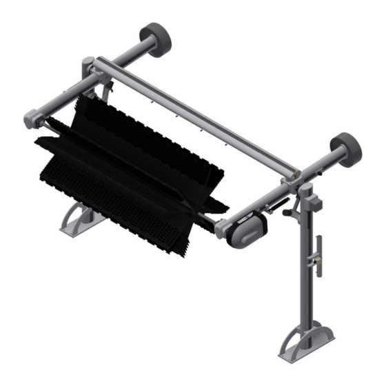
The Belanger, Inc.® TopWinder® is a component in the SpinLite® line of equipment for a tunnel system. The Belanger, Inc.® TopWinder® main function is to wash all the top surfaces of a vehicle. It is designed to operate in only 118-1/2” of tunnel space and is constructed of an aluminum framework which may also be powder coated in silver. -
Page 14: Before You Get Started
Notify your local distributor or Belanger, Inc.® immediately if shipment is determined damaged or incomplete. Belanger, Inc. ®* 1001 Doheny Ct. * Northville, MI 48167 * Ph (248) 349-7010 * Fax (248) 380-9681 1MANUL755... -
Page 15: Specifications
A compressed Air System should be set correctly to support 90 PSI necessary to operate equipment but should never be set to deliver more than 120 PSI air pressure to the Belanger® specified equipment. Belanger, Inc.® * 1001 Doheny Ct. * Northville, MI 48167 * Ph (248) 349-7010 * Fax (248) 380-9681 1MANUL755... -
Page 16: General Dimensions
® TopWinder Specifications General Dimensions 118-1/2” 150-7/8” 150-7/8” 133” When in Retract Position Belanger, Inc. ®* 1001 Doheny Ct. * Northville, MI 48167 * Ph (248) 349-7010 * Fax (248) 380-9681 1MANUL755... -
Page 17: Installation
3) The driver side Arm Assembly will also have two conduit fittings attached and the wires for the Motor/Gearbox and LED will be extending out of the fittings. Belanger, Inc.® * 1001 Doheny Ct. * Northville, MI 48167 * Ph (248) 349-7010 * Fax (248) 380-9681 1MANUL755... -
Page 18: Attaching The Crossbeam
3) The Crossbeam Assembly comes with the Filler Strip installed. Check to make sure the Filler Strips are secure and are the proper length. Belanger, Inc. ®* 1001 Doheny Ct. * Northville, MI 48167 * Ph (248) 349-7010 * Fax (248) 380-9681 1MANUL755... -
Page 19: Attaching The Legs
5/8 x 3-1/4” Shoulder Bolts. Then remove the shock assemblies. See the image below. 5/8 x 3-1/4” Shoulder Bolt Shock Arm Assembly Assembly Belanger, Inc.® * 1001 Doheny Ct. * Northville, MI 48167 * Ph (248) 349-7010 * Fax (248) 380-9681 1MANUL755... - Page 20 Leg Asy. Arm Asy. Arm Asy. Four (4) Bolts: Four (4) Bolts: 7/16-14 x 1” Driver Side Passenger Side 7/16-14 x 1” Belanger, Inc. ®* 1001 Doheny Ct. * Northville, MI 48167 * Ph (248) 349-7010 * Fax (248) 380-9681 1MANUL755...
-
Page 21: Identify Conveyor
Single Guide Rail Conveyor Assemblies (13” & 14-1/2” Wide) 13” 14-1/2” Guide Rail Double Guide Rail Conveyor Assemblies (13” & 14-1/2” Wide) 13” 14-1/2” Belanger, Inc.® * 1001 Doheny Ct. * Northville, MI 48167 * Ph (248) 349-7010 * Fax (248) 380-9681 1MANUL755... -
Page 22: Tunnel Placement
When utilizing Fusion Controller with pickup truck auto retract features, TopWinder® must be located so that ON position of controlling function is at least 40”. Belanger, Inc. ®* 1001 Doheny Ct. * Northville, MI 48167 * Ph (248) 349-7010 * Fax (248) 380-9681 1MANUL755... -
Page 23: Erecting The Frame
Legs on both sides. Lag the passenger side leg to the floor. Note: Verify that both arms make contact with the rubber Posi-Stops. Belanger, Inc.® * 1001 Doheny Ct. * Northville, MI 48167 * Ph (248) 349-7010 * Fax (248) 380-9681 1MANUL755... -
Page 24: Shock Assembly
2) Using the supplied 5/8” Shoulder Bolts, secure the unattached end of each Shock to the Clevis on the Arm Assemblies, as shown below. Secure Shock Assembly onto Arm Belanger, Inc. ®* 1001 Doheny Ct. * Northville, MI 48167 * Ph (248) 349-7010 * Fax (248) 380-9681 1MANUL755... -
Page 25: Auto Retract
After mounting and wiring the Photo-Eyes to the Leg Assemblies you will need to cut the Filler Strips to fit around the Photo-Eyes. Belanger, Inc.® * 1001 Doheny Ct. * Northville, MI 48167 * Ph (248) 349-7010 * Fax (248) 380-9681 1MANUL755... -
Page 26: Photo-Eye Mount Installation
Verify that the Photo-Eye Mount Assemblies are set at the appropriate height. Socket Head Fastener (2) Wedge Plate (2) Note: The Socket Head Fasteners pass through the Clamps and the Wedge Plates. Belanger, Inc. ®* 1001 Doheny Ct. * Northville, MI 48167 * Ph (248) 349-7010 * Fax (248) 380-9681 1MANUL755... -
Page 27: Wiring For The Auto Retract
Black - 338 (DC COM) until the Input is ON and remains ON. Belanger, Inc.® * 1001 Doheny Ct. * Northville, MI 48167 * Ph (248) 349-7010 * Fax (248) 380-9681 1MANUL755... -
Page 28: Photo-Eye Retract Cylinder
Mounting Plate Socket Head Fasteners Air Cushion Regulator Note: The large Socket Head Fastener passes through the Mounting Plate and Wedge Plate. Belanger, Inc. ®* 1001 Doheny Ct. * Northville, MI 48167 * Ph (248) 349-7010 * Fax (248) 380-9681 1MANUL755... -
Page 29: Filler Strip Installation For Leg Assemblies
2) For the Driver Side Leg Assembly trim the Filler Strip to the lengths called out in the image below and secure them in place. 3/4" 1-3/4" 4-5/16" 7-7/16" 27-11/16" 56-15/16" 3-1/2" 36-3/8" 7-7/8" 7-7/8" Driver Side Leg Assembly Belanger, Inc.® * 1001 Doheny Ct. * Northville, MI 48167 * Ph (248) 349-7010 * Fax (248) 380-9681 1MANUL755... - Page 30 4) The Filler Strips will need to be trimmed again if the wiring for the Photo-Eyes or the airlines for the Cylinder or Air Cushion are routed behind the Filler Strips. Belanger, Inc. ®* 1001 Doheny Ct. * Northville, MI 48167 * Ph (248) 349-7010 * Fax (248) 380-9681 1MANUL755...
-
Page 31: Air Panel & Air Cushion Installation
Air Valve Cushion 3/8” Airline to Air Regulator Cushion Regulator Cylinder 3/8” Airline for Cylinder Retract Air Cushion Regulator Retract Regulator Belanger, Inc.® * 1001 Doheny Ct. * Northville, MI 48167 * Ph (248) 349-7010 * Fax (248) 380-9681 1MANUL755... -
Page 32: Counterweight Installation
(penetration), we supply two 5 pound and one 10-pound weights. Bolt 4-3/4” 4-1/2” Length Approximate Weight: 18 - 20# Belanger, Inc. ®* 1001 Doheny Ct. * Northville, MI 48167 * Ph (248) 349-7010 * Fax (248) 380-9681 1MANUL755... - Page 33 The 3 holes will be equally spaced around the cover. See the image in Step 7 (on the next page). 5/8” Overhead View Belanger, Inc.® * 1001 Doheny Ct. * Northville, MI 48167 * Ph (248) 349-7010 * Fax (248) 380-9681 1MANUL755...
- Page 34 11) In a situation where the Counterweights are not needed, place the Rear Cover on the back of the arm and tighten it down with the provided 1/2-13 x 1” bolts and the flat washers. Belanger, Inc. ®* 1001 Doheny Ct. * Northville, MI 48167 * Ph (248) 349-7010 * Fax (248) 380-9681 1MANUL755...
-
Page 35: Installing The Drive Shaft And Hub Assembly
Arm Assembly Drive Shaft & Hub Assembly Key Slot Step 3: Orient Drive Shaft with Key Slot towards the Driver Side. Belanger, Inc.® * 1001 Doheny Ct. * Northville, MI 48167 * Ph (248) 349-7010 * Fax (248) 380-9681 1MANUL755... - Page 36 6) Loosen the set screws slightly on all the Shaft Bearings on both Arm Assemblies. Shaft Bearing Step 6: Slightly loosen the set screws on all Shaft Bearings. Belanger, Inc. ®* 1001 Doheny Ct. * Northville, MI 48167 * Ph (248) 349-7010 * Fax (248) 380-9681 1MANUL755...
- Page 37 9) Lift and slide the Drive Shaft and Hub Assembly into the end of the Arm Assemblies as shown below. Passenger Side Driver Side Step 9: Slide Drive Shaft and Hub Assembly into the end of the Arm Assemblies. Belanger, Inc.® * 1001 Doheny Ct. * Northville, MI 48167 * Ph (248) 349-7010 * Fax (248) 380-9681 1MANUL755...
- Page 38 13) On the driver side make sure the Locking Collar Groove on the Drive Shaft is past the bearing and is completely visible. Drive Shaft Step 13: Locking Collar Groove must be completely visible. Belanger, Inc. ®* 1001 Doheny Ct. * Northville, MI 48167 * Ph (248) 349-7010 * Fax (248) 380-9681 1MANUL755...
- Page 39 16) Make sure the Locking Collar is resting on the top of the Shaft Bearing and then tighten the set screws on all the Shaft Bearings. Belanger, Inc.® * 1001 Doheny Ct. * Northville, MI 48167 * Ph (248) 349-7010 * Fax (248) 380-9681 1MANUL755...
-
Page 40: Loading The Shinemitt™ Onto The Hub Assembly
4) Pull the Wire Harness Wires out of the End Plate holes and slide the End Plate toward the Arm Assembly. 5) Locate the ShineMitt™ there should be a total of 112 pieces. Clip ShineMitt™ 19” 45 Degree Short Lead Belanger, Inc. ®* 1001 Doheny Ct. * Northville, MI 48167 * Ph (248) 349-7010 * Fax (248) 380-9681 1MANUL755... - Page 41 8) Insert the LED Wires into the circular slots on the outer edge of the End Plate, shown below. Step 8: Insert the LED Wires in the circular slots on the End Plate. Belanger, Inc.® * 1001 Doheny Ct. * Northville, MI 48167 * Ph (248) 349-7010 * Fax (248) 380-9681 1MANUL755...
- Page 42 Fully Loaded Top Wheel with ShineMitt™ Step 14: Apply Anti-Seize™ to the fasteners and reattach the Hub Cap to the Hub Assembly. Belanger, Inc. ®* 1001 Doheny Ct. * Northville, MI 48167 * Ph (248) 349-7010 * Fax (248) 380-9681 1MANUL755...
-
Page 43: Connecting The Motor And Slip Ring To The Drive Shaft
Installed on Right 5) Secure the Motor Assembly to the Torque Studs using the Flat Washers and Cotter Pins, as shown above. Belanger, Inc.® * 1001 Doheny Ct. * Northville, MI 48167 * Ph (248) 349-7010 * Fax (248) 380-9681 1MANUL755... - Page 44 Slip Ring Shaft Slip Ring Plug 9) Slide the Slip Ring Shaft over the Slip Ring Plug Wire, shown in image above. Belanger, Inc. ®* 1001 Doheny Ct. * Northville, MI 48167 * Ph (248) 349-7010 * Fax (248) 380-9681 1MANUL755...
- Page 45 13) Secure the Slip Ring to the Torque Mount on the Motor, see images below. Torque Mount Shoulder Bolt: 5/16” X 3/4" Nut: 1/4”-20 Belanger, Inc.® * 1001 Doheny Ct. * Northville, MI 48167 * Ph (248) 349-7010 * Fax (248) 380-9681 1MANUL755...
- Page 46 Conduit supplied and into the bottom of the Motor Cover. Motor Cover 24VDC LED Motor Wires Power Supply Cable Driver Side Arm Conduit Belanger, Inc. ®* 1001 Doheny Ct. * Northville, MI 48167 * Ph (248) 349-7010 * Fax (248) 380-9681 1MANUL755...
- Page 47 18) Wrap the wire connection with electrical tape and tuck inside the Motor Cover. Step 18: Wrap connection with electrical tape. Belanger, Inc.® * 1001 Doheny Ct. * Northville, MI 48167 * Ph (248) 349-7010 * Fax (248) 380-9681 1MANUL755...
-
Page 48: Electric Motor Installation
4) After the Motor has been wired, secure the Upper Cover onto the plastic Motor Cover using the supplied self-tapping screws. Belanger, Inc. ®* 1001 Doheny Ct. * Northville, MI 48167 * Ph (248) 349-7010 * Fax (248) 380-9681 1MANUL755... -
Page 49: Main Water Feed
Doing so will prevent the utilities from being damaged during the pivoting motion of the Top Wheel. 3/4” Main Water Feed Main Lead Motor/Gearbox Main Lead Belanger, Inc.® * 1001 Doheny Ct. * Northville, MI 48167 * Ph (248) 349-7010 * Fax (248) 380-9681 1MANUL755... -
Page 50: Startup
BE AWARE OF THE AREA SURROUNDING A ROTATING PIECE OF EQUIPMENT. OBJECTS MAY BECOME TANGLED WITH EQUIPMENT AND COULD RESULT IN SERIOUS INJURY OR DEATH. Belanger, Inc. ®* 1001 Doheny Ct. * Northville, MI 48167 * Ph (248) 349-7010 * Fax (248) 380-9681 1MANUL755... -
Page 51: Verify Retract Pressure (If Applicable)
7) Verify that the Retract Cylinder (if applicable) is operating properly and that the PSI setting on the regulator is correct. Adjust as necessary. Belanger, Inc.® * 1001 Doheny Ct. * Northville, MI 48167 * Ph (248) 349-7010 * Fax (248) 380-9681 1MANUL755... -
Page 52: Maintenance
Monthly • Wash TopWinder® components down. See Powder Coat Cleaning procedure. • Check ShineMitt™ cleaning material for wear. Replace if necessary. Belanger, Inc. ®* 1001 Doheny Ct. * Northville, MI 48167 * Ph (248) 349-7010 * Fax (248) 380-9681 1MANUL755... -
Page 53: Powder Coating Maintenance
If you have any questions or concerns regarding how to clean powder coat equipment, please call Belanger® Technical Support / Aftermarket Group for additional assistance. Belanger, Inc.® * 1001 Doheny Ct. * Northville, MI 48167 * Ph (248) 349-7010 * Fax (248) 380-9681 1MANUL755... -
Page 54: Powder Coating Repair
Continue rubbing down and applying light coats, until the edges of the damaged paint have disappeared. Applied properly, at this stage all physical signs of repair can be lost. Belanger, Inc. ®* 1001 Doheny Ct. * Northville, MI 48167 * Ph (248) 349-7010 * Fax (248) 380-9681 1MANUL755... - Page 55 The result is that it will peel off. It is always a good practice to mechanically abrade a key by using rubbing down paper, or at least use a non-scratch scrub sponge. A small discrete area should be tested first. Belanger, Inc.® * 1001 Doheny Ct. * Northville, MI 48167 * Ph (248) 349-7010 * Fax (248) 380-9681 1MANUL755...
-
Page 56: Hub Led Light Replacement
5) Locate the Hub LED light that needs to be replaced. Remove the LED from the Hub Channel. 6) Install the new Hub LED light assembly into the channel, shown below. LED Assembly Hub Channel Belanger, Inc. ®* 1001 Doheny Ct. * Northville, MI 48167 * Ph (248) 349-7010 * Fax (248) 380-9681 1MANUL755... - Page 57 10) Wrap the new LED light connection with electrical tape to protect it from the car wash elements. Belanger, Inc.® * 1001 Doheny Ct. * Northville, MI 48167 * Ph (248) 349-7010 * Fax (248) 380-9681 1MANUL755...
- Page 58 14) Apply Anti-Seize™ to the Hub Cap Fasteners and reassemble the Hub Cap back onto the Hub Assembly. Step 14: Apply Anti-Seize™ to the fasteners and reattach the Hub Cap to the Hub Assembly. Belanger, Inc. ®* 1001 Doheny Ct. * Northville, MI 48167 * Ph (248) 349-7010 * Fax (248) 380-9681 1MANUL755...
-
Page 59: Torque Plate And Electric Motor Replacement
5) Confirm that the wiring has been tagged for terminal location if not previously identified upon installation. Remove the nuts to release wiring from the Terminal Block. See the image below. Belanger, Inc.® * 1001 Doheny Ct. * Northville, MI 48167 * Ph (248) 349-7010 * Fax (248) 380-9681 1MANUL755... - Page 60 8) Remove the Retainer Disk fasteners from the top of the Slip Ring. Step 8: Remove the fasteners from the Retainer Disk. Belanger, Inc. ®* 1001 Doheny Ct. * Northville, MI 48167 * Ph (248) 349-7010 * Fax (248) 380-9681 1MANUL755...
- Page 61 Slip Ring off of the Slip Ring Shaft. Step 11: Unthread the Slip Ring Shaft from the Drive Shaft. Belanger, Inc.® * 1001 Doheny Ct. * Northville, MI 48167 * Ph (248) 349-7010 * Fax (248) 380-9681 1MANUL755...
- Page 62 You will need a work surface such as a table or a bench available to allow for disassembly of the Gearbox Torque Plate. Belanger, Inc. ®* 1001 Doheny Ct. * Northville, MI 48167 * Ph (248) 349-7010 * Fax (248) 380-9681 1MANUL755...
- Page 63 Torque Plate. See the images below. Torque Plate & Mounting Ring Flat Head Socket M8 X 40 Black Oxide Belanger, Inc.® * 1001 Doheny Ct. * Northville, MI 48167 * Ph (248) 349-7010 * Fax (248) 380-9681 1MANUL755...
- Page 64 8) To ensure the fasteners will set appropriately, allow this assembly to cure at least 24 hours in a warm (70 degree) environment. Note: Loctite takes at least this length of time to cure properly. Belanger, Inc. ®* 1001 Doheny Ct. * Northville, MI 48167 * Ph (248) 349-7010 * Fax (248) 380-9681 1MANUL755...
- Page 65 4) Apply Anti-Seize™ to the threads on the Drive Shaft. Thread the Jam Nut onto the end of the Drive Shaft. Step 4: Apply Anti-Seize™ then thread the Jam Nut onto the Drive Shaft. Belanger, Inc.® * 1001 Doheny Ct. * Northville, MI 48167 * Ph (248) 349-7010 * Fax (248) 380-9681 1MANUL755...
- Page 66 Step 8b: Slide the Slip Ring onto the Slip Ring Shaft. Step 8a: Thread the Slip Ring Shaft onto the Drive Shaft. Belanger, Inc. ®* 1001 Doheny Ct. * Northville, MI 48167 * Ph (248) 349-7010 * Fax (248) 380-9681 1MANUL755...
- Page 67 11) Secure the Wire Retainer Disk to the top of the Slip Ring Shaft using the two 8-32 X 1/2” screws. Step 11: Attach the Retainer Disk to the Slip Ring Shaft. Belanger, Inc.® * 1001 Doheny Ct. * Northville, MI 48167 * Ph (248) 349-7010 * Fax (248) 380-9681 1MANUL755...
- Page 68 Wrap connection with electrical tape. 14) Wrap the wire connection with electrical tape and tuck inside the Motor Cover. Belanger, Inc. ®* 1001 Doheny Ct. * Northville, MI 48167 * Ph (248) 349-7010 * Fax (248) 380-9681 1MANUL755...
- Page 69 19) Verify wheel rotation prior to running any test vehicle through the system. 20) Secure the Upper Cover onto the Motor Cover Base. Belanger, Inc.® * 1001 Doheny Ct. * Northville, MI 48167 * Ph (248) 349-7010 * Fax (248) 380-9681 1MANUL755...
-
Page 70: Maintenance (Continued)
LED Lights Slip Ring Cable connects Wire Harness for LED Lights to Wire Harness Receptor Four (4) Plugs connect to LEDs Belanger, Inc. ®* 1001 Doheny Ct. * Northville, MI 48167 * Ph (248) 349-7010 * Fax (248) 380-9681 1MANUL755... -
Page 71: Driver Side Leg Assembly (Aluminum: 110779 & Silver Pc: 110799): Overview
SEE EXPLODED VIEW BELOW ASSEMBLED EXPLODED ITEMS SHOWN IN ZONES 6 AND 7 ARE NOT INCLUDED IN ASSEMBLY 110779 & 110799 Belanger, Inc.® * 1001 Doheny Ct. * Northville, MI 48167 * Ph (248) 349-7010 * Fax (248) 380-9681 1MANUL755... -
Page 72: Driver Side Leg Assembly (Aluminum: 110779 & Silver Pc: 110799) - Zone 1
1FSTNR-HH354 (2) PASS THRU HOLES IN 110774 / 110887 AND ARE SECURED BY THREADS IN 9885 / 9886. 1FSTNR-SB563 Aluminum: 110774 Silver PC: 110887 Belanger, Inc. ®* 1001 Doheny Ct. * Northville, MI 48167 * Ph (248) 349-7010 * Fax (248) 380-9681 1MANUL755... -
Page 73: Driver Side Leg Assembly (Aluminum: 110779 & Silver Pc: 110799) - Zone 4
110797 / 108564 AND 110774 / 110887 THEN ASSEMBLIES THEY ARE SECURED BY THREADS IN THE ARE PART OF THE OTHER SIDE OF 110797 / 108564. ACCESSORY BOX Belanger, Inc.® * 1001 Doheny Ct. * Northville, MI 48167 * Ph (248) 349-7010 * Fax (248) 380-9681 1MANUL755... -
Page 74: Driver Side Leg Assembly (Aluminum: 110779 & Silver Pc: 110799) - Zone 6
Driver Side Leg Assembly (Aluminum: 110779 & Silver PC: 110799) – Zone 7 DRIVER SIDE ONLY 1ELECT-FS176 (2) 1WASHR500 (2) 1ELECT-FS750 (2) 9715 1ELECT-FS232 9715 Aluminum: 110774 Silver PC: 110887 1FSTNR-SH080 (4) Belanger, Inc. ®* 1001 Doheny Ct. * Northville, MI 48167 * Ph (248) 349-7010 * Fax (248) 380-9681 1MANUL755... -
Page 75: Passenger Side Leg Assembly (Aluminum: 110801 & Silver Pc: 110914): Overview
SEE EXPLODED VIEW ABOVE IN DRIVER SIDE LEG ASSEMBLY ITEMS SHOWN IN ZONES 6 AND 7 ARE NOT INCLUDED IN ASSEMBLY 110801 /110914 ASSEMBLED EXPLODED Belanger, Inc.® * 1001 Doheny Ct. * Northville, MI 48167 * Ph (248) 349-7010 * Fax (248) 380-9681 1MANUL755... -
Page 76: Passenger Side Leg Assembly (Aluminum: 110801 & Silver Pc: 110914) - Zone 7
Aluminum: 9840 Black PC: 9385 1WASHR-LC291 (2) 1FSTNR-HH354 (2) PASS THRU HOLES IN 110796/108693 AND ARE SECURED BY THREADS IN 9840/9385. Belanger, Inc. ®* 1001 Doheny Ct. * Northville, MI 48167 * Ph (248) 349-7010 * Fax (248) 380-9681 1MANUL755... -
Page 77: Passenger Side Leg Assembly (Aluminum: 110801 & Silver Pc: 110914) - Zone 6
LENGTHS NEEDED ARE SHOWN ON THE LEFT. Full Length (70’) Filler Strip Silver 1PLSTC-EX062 48-3/4” 7-7/8” Aluminum: 110797 7-7/8” Silver PC: 108564 Belanger, Inc.® * 1001 Doheny Ct. * Northville, MI 48167 * Ph (248) 349-7010 * Fax (248) 380-9681 1MANUL755... -
Page 78: Driver Side Arm Assembly (Aluminum: 110941 & Silver Pc: 110955): Overview
PART NUMBER FOR FULL (120”) FILLER STRIPS AND LENGTHS TO CUT STRIPS ARE SHOWN IN DRIVER SIDE ARM ASSEMBLY – ZONE 4. Belanger, Inc. ®* 1001 Doheny Ct. * Northville, MI 48167 * Ph (248) 349-7010 * Fax (248) 380-9681 1MANUL755... -
Page 79: Driver Side Arm Assembly (Aluminum: 110941 & Silver Pc: 110955) - Zone 1
1WASHR-LC581 (4) 1WASHR-LC291 1FSTNR-HH684 (2) 1FSTNR-HH288 1FSTNR-HH630 (2) PASS THRU HOLES IN 9941/9952 AND 110942/110956 THEN ARE SECURED BY THREADS IN 9942/9953. Belanger, Inc.® * 1001 Doheny Ct. * Northville, MI 48167 * Ph (248) 349-7010 * Fax (248) 380-9681 1MANUL755... -
Page 80: Driver Side Arm Assembly (Aluminum: 110941 & Silver Pc: 110955) - Zone 2
INCLUDED IN THE ARM ASSEMBLIES. SEE ZONE 4 Aluminum: 110793 Black PC: 108671 1FSTNR-SH882 (6) Aluminum: 110942 SEE ZONE 4 Silver PC: 110956 Belanger, Inc. ®* 1001 Doheny Ct. * Northville, MI 48167 * Ph (248) 349-7010 * Fax (248) 380-9681 1MANUL755... -
Page 81: Driver Side Arm Assembly (Aluminum: 110941 & Silver Pc: 110955) - Zone 4
Driver Side Arm Assembly (Aluminum: 110941 & Silver PC: 110955) – Zone 4 Full Length (70’) Filler Strip Aluminum: 110941 Silver 1PLSTC-EX062 Silver PC: 110955 35-5/8” 28” 11-11/16” 3-3/4” 14-1/8” 8-1/8” 15-1/4” Belanger, Inc.® * 1001 Doheny Ct. * Northville, MI 48167 * Ph (248) 349-7010 * Fax (248) 380-9681 1MANUL755... -
Page 82: Passenger Side Arm Assembly (Aluminum: 110948 & Silver Pc: 110957)
Aluminum: 9944 Aluminum: 1BERNG848 Black PC: 9954 Silver PC: 1BERNG849 7926 (2) 1WASHR-LC581 (4) 1FSTNR-HH684 (4) Aluminum: 9942 Silver PC: 9953 Belanger, Inc. ®* 1001 Doheny Ct. * Northville, MI 48167 * Ph (248) 349-7010 * Fax (248) 380-9681 1MANUL755... -
Page 83: Passenger Side Arm Assembly (Aluminum: 110948 & Silver Pc: 110957) - Zone 2
Black PC: 108671 NO FILLER STRIPS ARE INCLUDED IN THE ARM ASSEMBLIES. Aluminum: 110942 SEE ZONE 4 Silver PC: 110956 1FSTNR-SH882 (6) Belanger, Inc.® * 1001 Doheny Ct. * Northville, MI 48167 * Ph (248) 349-7010 * Fax (248) 380-9681 1MANUL755... -
Page 84: Passenger Side Arm Assembly (Aluminum: 110948 & Silver Pc: 110957) - Zone 4
Passenger Side Arm Assembly (Aluminum: 110948 & Silver PC: 110957) – Zone 4 Aluminum: 110948 Silver PC: 110957 35-5/8” 20-1/8” 28” 14” 2-1/16” 24-7/16” Full Length (70’) Filler Strip 1PLSTC-EX062 Silver Belanger, Inc. ®* 1001 Doheny Ct. * Northville, MI 48167 * Ph (248) 349-7010 * Fax (248) 380-9681 1MANUL755... -
Page 85: Crossbeam Assembly: Overview
7926 (2) 1FSTNR-SH177 (2) 1FTTNG-BH286 Aluminum: 9831 1VALVE-WA231 PC Silver: 9303 1ELBOW-BR381 Aluminum: 9932 PC Silver: 9949 1ELBOW-BR381 1FTTNG-BH286 1VALVE-WA231 7926 Belanger, Inc.® * 1001 Doheny Ct. * Northville, MI 48167 * Ph (248) 349-7010 * Fax (248) 380-9681 1MANUL755... -
Page 86: Crossbeam Assembly: Filler Strips
® TopWinder Maintenance Exploded Parts Crossbeam Assembly: Filler Strips 128-1/4” 119-1/2” Full Length (70’) Filler Strip Silver 1PLSTC-EX062 Belanger, Inc. ®* 1001 Doheny Ct. * Northville, MI 48167 * Ph (248) 349-7010 * Fax (248) 380-9681 1MANUL755... -
Page 87: Counterweight Components
1PLSTC-CR470 (2) (includes both pieces) 6834 6833 1WASHR-LC456 (6) 6833 6833 1WASHR-FL706 (6) 6833 6833 8282 8282 8283 8283 1CLIP-PL250 (6) Belanger, Inc.® * 1001 Doheny Ct. * Northville, MI 48167 * Ph (248) 349-7010 * Fax (248) 380-9681 1MANUL755... -
Page 88: Hub & Shaft Assembly Overview: 111359
6144 (4) 9945 1FSTNR-BH505 (4) 10341 1WASHR-LC291 (2) 9724 1FSTNR-HH288 (2) 9723 1FSTNR-PH108 (2) Cable: 111363 10172 See image on page 84 Belanger, Inc. ®* 1001 Doheny Ct. * Northville, MI 48167 * Ph (248) 349-7010 * Fax (248) 380-9681 1MANUL755... -
Page 89: Hub & Shaft Assembly 111359 - Zone 2
1NUT-RG402 (2) 1NUT-LC214 Middle Spider Assembly: 111358 1FSTNR-HH198 (2) 1WASHR-FL415 (2) 1WASHR-LC270 (2) 111356 (2) 1NUT-RG402 (2) End Spider Assemblies: 111357 (2) Belanger, Inc.® * 1001 Doheny Ct. * Northville, MI 48167 * Ph (248) 349-7010 * Fax (248) 380-9681 1MANUL755... -
Page 90: Hub & Shaft Assembly 111359 - Zone 3
Maintenance Exploded Parts Hub & Shaft Assembly 111359 – Zone 3 10342 1FSTNR-HH288 (2) 1WASHR-LC291 (2) 6144 (4) 1FSTNR-BH505 (4) 10341 Belanger, Inc. ®* 1001 Doheny Ct. * Northville, MI 48167 * Ph (248) 349-7010 * Fax (248) 380-9681 1MANUL755... -
Page 91: Motor Drive Assembly (60 Hz): Overview
Motor Drive Assembly (60 Hz): Motor Gearbox 110935 (STDV) or 110967 (575V) 108661 1ELECT-FS855 (4) 7912 1FSTNR-FH075 (8) 1HP STDV: 112273 1HP 575V: 112274 9721 Belanger, Inc.® * 1001 Doheny Ct. * Northville, MI 48167 * Ph (248) 349-7010 * Fax (248) 380-9681 1MANUL755... -
Page 92: Motor Drive Assembly (60 Hz): Motor Gearbox Cover 110720
Assembly 111359 See Part Numbers 111362 Below and Installed on See Exploded View Left on Following Page 1WASHR-FL747 (2) 1RENTR129 (2) Belanger, Inc. ®* 1001 Doheny Ct. * Northville, MI 48167 * Ph (248) 349-7010 * Fax (248) 380-9681 1MANUL755... -
Page 93: Motor Drive Assembly (60 Hz): Slip Ring 111362
Motor Drive Assembly (60 Hz): Conduit & Power Cables 110886: 24VDC LED Power Supply Cable 1ELECT-FS230 Length: 5FT 1ELECT-FS231 1ELECT-CB874 Motor Power Supply Cable Belanger, Inc.® * 1001 Doheny Ct. * Northville, MI 48167 * Ph (248) 349-7010 * Fax (248) 380-9681 1MANUL755... -
Page 94: Slip Ring To Wire Harness Cable: 111363
Slip Ring for LED Lights 110718: Wire Harness Slip Ring Cable connects Four (4) Plugs connect to Wire Harness Receptor to LEDs 110945 Belanger, Inc. ®* 1001 Doheny Ct. * Northville, MI 48167 * Ph (248) 349-7010 * Fax (248) 380-9681 1MANUL755... -
Page 95: Shinemitt™ Fill Pattern
Height: 84-1/16” 14 Rows of ShineMitt™ Fill 111060 with a quantity of 8 per Row (19” - 45 DEG Short Lead) Belanger, Inc.® * 1001 Doheny Ct. * Northville, MI 48167 * Ph (248) 349-7010 * Fax (248) 380-9681 1MANUL755... - Page 96 Maintenance Replacement Parts ShineMitt™ 19-inch 45 Degree Short Lead: 111060 (Qty. 112) 10010 10011 1PLSTC-CL010 (2) 9985 (21) 2.7” (Short Lead) Belanger, Inc. ®* 1001 Doheny Ct. * Northville, MI 48167 * Ph (248) 349-7010 * Fax (248) 380-9681 1MANUL755...
-
Page 97: Air Cushion Regulator Assembly: (Aluminum: 110906 & Silver Pc: 110907)
1FSTNR-SH177 (2) Aluminum: 9898 Black PC: 9899 1RGLTR750 1ELBOW-PL535 (2) 1REDUC-ST111 1GUAGE500 1AIRLN635 (2) 3/8” Natural Plastic Airline Length: 110 FT Belanger, Inc.® * 1001 Doheny Ct. * Northville, MI 48167 * Ph (248) 349-7010 * Fax (248) 380-9681 1MANUL755... -
Page 98: Retract Assembly With Photo-Eye Set: (Aluminum: 110805 / Silver Pc: 107193)
When replacing a Photo-Eye be sure to position the clear LED indicators toward the closest end to make verification of operation easier. Belanger, Inc. ®* 1001 Doheny Ct. * Northville, MI 48167 * Ph (248) 349-7010 * Fax (248) 380-9681 1MANUL755... -
Page 99: Retract Air Panel: 102913
2501 (2) 1VALVE-EL370 (2) 1WASHR-LC115 (4) 1TEE-PL706 1FSTNR-SH059 (4) 3699 2529 1MADAP-BR600 1AIRLN275 1MADAP-BR600 1ELBOW-PL666 1AIRLN165 1VALVE-PN405 (2) 1ELBOW-PL535 (2) 1GAUGE500 1RGLTR175 Belanger, Inc.® * 1001 Doheny Ct. * Northville, MI 48167 * Ph (248) 349-7010 * Fax (248) 380-9681 1MANUL755...
Need help?
Do you have a question about the Top Winder and is the answer not in the manual?
Questions and answers