
Related Manuals for Belanger FLIPPING

Summary of Contents for Belanger FLIPPING
- Page 1 FLIPPING™ ARCH Belanger, Inc®. P.O. Box 5470 Northville, MI 48167-5470 Customer Service Phone (248) 349-7010 Fax (248) 380-9681 www.Belangerinc.com 1MANUL027 REV 00...
- Page 2 Do not make additional copies of this manual or electronically transmit it in any form ® whatsoever, in whole or in part, without the prior written permission of Belanger, Inc. The registered trademarks used in this document are the property of their respective owners. The use of such trademarks is ®...
-
Page 3: Table Of Contents
Leg Manifold Mounting Overall ......................32 Air Panel ............................33 Top Manifold and Nozzles ........................ 34 Leg Manifold and Nozzles ........................ 34 Optional Rain Bar Assembly ......................35 Belanger®, Inc. *PO BOX 5470 *Northville, MI 48167-5470 * Ph (248) 349-7010 * Fax (248) 380-9681 1MANUL027... -
Page 4: Belanger Incorporated® Limited Warranty
PURPOSE CONTAINED IN THE UNIFORM COMMERCIAL CODE – SALES ARE EXPRESSLY DISCLAIMED. Copyright ©2013 by Belanger, Inc. All rights reserved. No part of this work may be reproduced or transmitted in any form or by any means, electronic or mechanical, including photocopying and recording, or by any information storage or retrieval system, except as may be expressly permitted by the 1976 Copyright Act. -
Page 5: Operational Warning
Belanger, Inc.®, does not endorse or condone the use of chemicals that are potentially dangerous to human health, the environment or property. Belanger® recognizes that it is the right and sole decision of the end user operators of our equipment as to the type and dilution ratio of the chemicals used in their facilities. We strongly recommend that the end user does not select products containing any of the chemicals listed above as an ingredient in the wash solutions. -
Page 6: Introduction
If you do not understand the procedure, call a Belanger, Inc.® representative at 248-349-7010. It is imperative to your safety and the safety of others to understand the procedures before beginning work. Belanger, Inc.® *PO BOX 5470 *Northville, MI 48167-5470 * Ph (248) 349-7010 * Fax (248) 380-9681 1MANUL027... -
Page 7: Important Safety Information - Must Read
Doing so will prevent unexpected energization, startup, or release of hazardous energy while maintenance and servicing activities are being performed. Belanger®, Inc. *PO BOX 5470 *Northville, MI 48167-5470 * Ph (248) 349-7010 * Fax (248) 380-9681 1MANUL027... - Page 8 THAT MAY BE A TRIP HAZARD. It is imperative to your safety and the safety of others to always follow safe work procedures. Belanger, Inc.® *PO BOX 5470 *Northville, MI 48167-5470 * Ph (248) 349-7010 * Fax (248) 380-9681 1MANUL027...
-
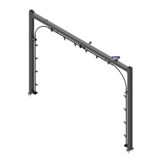
Page 9: Overview
The retract feature of the Flipping™ Arch sets the home position for the manifolds at the center of the arch and still allows 30° of rotation toward the exit of the tunnel. Depending on the delivery system and nozzle configuration purchased, the Arch can have either a single or dual feed utility connection. -
Page 10: Before You Get Started
Notify your local distributor or Belanger, Inc.® immediately if shipment is determined damaged or incomplete. Belanger, Inc.® *PO BOX 5470 *Northville, MI 48167-5470 * Ph (248) 349-7010 * Fax (248) 380-9681 1MANUL027... -
Page 11: Available Nozzle Options
Nozzles are selected separately based on your pump station option. This ensures maximum performance of your Flipping™ Arch. The Flooder nozzle kit is not listed below and should NOT be used with the Flipping™ Arch due to flow requirements. -
Page 12: Specifications
CAUTION A compressed Air System should be set correctly to support 90 PSI necessary to operate equipment, but should never be set to deliver more than 120 PSI air pressure to the Belanger® specified equipment. Belanger, Inc.® *PO BOX 5470 *Northville, MI 48167-5470 * Ph (248) 349-7010 * Fax (248) 380-9681... -
Page 13: Dimensions
Not To Scale Not to Scale Not to Scale 93-1/2” 107-1/4” Vehicle Clearance Component Height 129-9/16” Vehicle Clearance 8” Tunnel Space 152-3/16” Component Width Belanger®, Inc. *PO BOX 5470 *Northville, MI 48167-5470 * Ph (248) 349-7010 * Fax (248) 380-9681 1MANUL027... -
Page 14: Installation
Place the Cylinder Retraction Bumper on the shaft and reinstall the Cylinder Bearing and Jam Nut. Cylinder Retraction Cylinder Bumper Bearing Jam Nut Cylinder Shaft BEFORE AFTER Belanger, Inc.® *PO BOX 5470 *Northville, MI 48167-5470 * Ph (248) 349-7010 * Fax (248) 380-9681 1MANUL027... - Page 15 Leg Assembly (2) View of Head and Leg Assemblies from ABOVE. You will be facing the EXIT side of the Arch Direction Of Travel Belanger®, Inc. *PO BOX 5470 *Northville, MI 48167-5470 * Ph (248) 349-7010 * Fax (248) 380-9681 1MANUL027...
- Page 16 Installation Arch Assembly 3. Stand the Arch up so that the Flipping Cylinder Assembly is facing the Exit of the tunnel. See the image below. Position the Arch so that the distance between the back of the Driver side Leg and the inside edge of the conveyor guiderail is 49-3/8”.
- Page 17 (2) 3/4" Hose Barbs with with a Check Valve and 3/4" Hose Barb Check Valves (1) 1/4" Poly-Flow Tube Connection with a Check Valve Belanger®, Inc. *PO BOX 5470 *Northville, MI 48167-5470 * Ph (248) 349-7010 * Fax (248) 380-9681 1MANUL027...
- Page 18 Nozzle Port (4) Nozzle Port (4) Note: VERIFY THAT THE 1/2" HYDRAULIC HOSE ASSEMBLIES ARE NOT TWISTED. Tighten both 1/2" Hydraulic Hose Assemblies completely. Belanger, Inc.® *PO BOX 5470 *Northville, MI 48167-5470 * Ph (248) 349-7010 * Fax (248) 380-9681 1MANUL027...
-
Page 19: Nozzle Kits
Apply Liquid Teflon™ to the Threads at Installation Check Body (4) in Each Leg Check Cap Leg Check Body Orientation – Check Cap Facing Toward the Ground Belanger®, Inc. *PO BOX 5470 *Northville, MI 48167-5470 * Ph (248) 349-7010 * Fax (248) 380-9681 1MANUL027... - Page 20 You may need more than one type of nozzle. 4. Electrically connect any optional equipment to the car wash controller unit (if applicable). Belanger, Inc.® *PO BOX 5470 *Northville, MI 48167-5470 * Ph (248) 349-7010 * Fax (248) 380-9681 1MANUL027...
-
Page 21: Optional Rain Bar Installation
Attach the Mounting Channel Wedments and the Half Clamps to the Head Assembly as shown in the image below. 1/2" Lock Washers (8) 1/2" Flat Washer Half Clamp Mounting Channel Weldments (2) Head Assembly Belanger®, Inc. *PO BOX 5470 *Northville, MI 48167-5470 * Ph (248) 349-7010 * Fax (248) 380-9681 1MANUL027... - Page 22 5. Run a Field Supplied 3/4" water hose from the Barb Hose Fitting of the Rain Bar to the main water supply. 6. Flush out the Rain Bar Assembly to remove any debris. Belanger, Inc.® *PO BOX 5470 *Northville, MI 48167-5470 * Ph (248) 349-7010 * Fax (248) 380-9681 1MANUL027...
-
Page 23: Utility Connections
Cylinder. See the images above. Note: Each port on the Cylinder has flow controls to adjust the cylinder actuation speed. See the image above. Belanger®, Inc. *PO BOX 5470 *Northville, MI 48167-5470 * Ph (248) 349-7010 * Fax (248) 380-9681 1MANUL027... - Page 24 Valve and (1) 1/4" Poly Flow Tube Connection with Check Valve for Main Water Connection 3/4” NPT 3/4” NPT Main Feed Block Direction Of Travel Belanger, Inc.® *PO BOX 5470 *Northville, MI 48167-5470 * Ph (248) 349-7010 * Fax (248) 380-9681 1MANUL027...
-
Page 25: Initial Start Up
FLIPPING™ ARCH Installation Initial Start Up 1) Run water through the Flipping™ Arch and verify that there are no leaks in any of the fittings or connections. 2) Actuate the 4-way valve on the air panel. 3) Verify that the Head Assembly Spray Manifold ROTATES correctly. - Page 26 Leg Manifold Assembly (2) 5) Run a test wash on a vehicle. 6) Program the Flipping™ Arch so that it activates just before the front bumper of the vehicle comes in contact with the spray application. 7) Program the air panel so that the 4-way valve activates when the spray application is at the side rear view mirrors.
-
Page 27: Maintenance
Disassemble and clean solenoid valve Kink in hose Remove any kinks from hose Inadequate water pressure Open water valve to fullest Belanger®, Inc. *PO BOX 5470 *Northville, MI 48167-5470 * Ph (248) 349-7010 * Fax (248) 380-9681 1MANUL027... -
Page 28: Replacement Parts
See the Exploded View Head Beam Weldment See the Exploded View Main Feed Block Assembly Upper Manifold Mounting See the Exploded View 1FSTNR-HH346 (2) 1WASHR-LC291(2) 9575 Belanger, Inc.® *PO BOX 5470 *Northville, MI 48167-5470 * Ph (248) 349-7010 * Fax (248) 380-9681 1MANUL027... -
Page 29: Head Beam Weldment (110549)
(4) Per Corner 100704 (2) Hose Assembly (2) FASTENER SETS ONE FOR EACH CORNER ARE NEEDED FOR EACH FLIPPING™ ARCH Leg Assembly Ref Belanger®, Inc. *PO BOX 5470 *Northville, MI 48167-5470 * Ph (248) 349-7010 * Fax (248) 380-9681 1MANUL027... -
Page 30: Upper Manifold Mounting And Upper Lens
1WASHR-LC291 (2) 2744 (2) 9575 1CLAMP478 (2) Main Feed Block 1HOSE650 1MCONC-BR751 (3) 1HOSE-HY025 115027 Optional High Pressure Feed Kit May Replace 115022 Belanger, Inc.® *PO BOX 5470 *Northville, MI 48167-5470 * Ph (248) 349-7010 * Fax (248) 380-9681 1MANUL027... -
Page 31: Upper Manifold Mounting Overall
Center of Manifold 110550 1REDUC-SS220 (1) on Each End 1MCONC-SS030 1FSTNR-SB150 (1) on Each End (3) on Each End 1COLLR250 (1) on Each End Belanger®, Inc. *PO BOX 5470 *Northville, MI 48167-5470 * Ph (248) 349-7010 * Fax (248) 380-9681 1MANUL027... -
Page 32: Upper Manifold Mounting Zone 2 - Step 1
SEE ZONE 2 – STEP 2 BELOW 110550 Upper Manifold Mounting Zone 2 – Step 2 1BERNG040 9445 9455 1VALVE-PN180 (2) 1NUT-JM084 1CYLND204 Belanger, Inc.® *PO BOX 5470 *Northville, MI 48167-5470 * Ph (248) 349-7010 * Fax (248) 380-9681 1MANUL027... -
Page 33: Flipping™ Arch Side Leg Assembly Components Overview
9541 110548 Leg Weldment See the Exploded Views on the Right 1FSTNR-ST500 (4) per Leg Side Manifold Mounting See the Exploded View 9550 Belanger®, Inc. *PO BOX 5470 *Northville, MI 48167-5470 * Ph (248) 349-7010 * Fax (248) 380-9681 1MANUL027... -
Page 34: Leg Manifold Mounting Overall
Leg Weldment Ref Leg Manifold Mounting – Zone 2 110501 1FSTNR-HH315 (2) 1WASHR-LC291(2) 1FSTNR-ST500 (4) on Each Leg 9578 (2) 9539 Leg Weldment Ref 1PLUG-SS575 Belanger, Inc.® *PO BOX 5470 *Northville, MI 48167-5470 * Ph (248) 349-7010 * Fax (248) 380-9681 1MANUL027... -
Page 35: Air Panel
3699 1AIRLN220 1RGLTR175 1ELBOW-PL666 1GAUGE500 1RGLTR175 1VALVE-EL710 2529 1FSTNR-SH177 (4) 1WASHR-LC115 (4) 1FSTNR-HH081 (2) 120 VAC 1WASHR-LC125 (2) 1MADAP-BR600 TO MAIN AIR CONNECTION Belanger®, Inc. *PO BOX 5470 *Northville, MI 48167-5470 * Ph (248) 349-7010 * Fax (248) 380-9681 1MANUL027... -
Page 36: Top Manifold And Nozzles
(4) per Leg Assembly 1NOZZL972 (4) per Leg Assembly See Available Nozzle Options in the Introduction Section of this Manual Quantity = 4 Belanger, Inc.® *PO BOX 5470 *Northville, MI 48167-5470 * Ph (248) 349-7010 * Fax (248) 380-9681 1MANUL027... -
Page 37: Optional Rain Bar Assembly
9561 (2) Rain-100: 100 Hole Manifold Rain-200: 200 Hole Manifold Rain-300: 300 Hole Manifold 6849 (2) 1NUT-LC214 (4) 1PLUG-SS575 Assembled Flipping™ Arch Ref Belanger®, Inc. *PO BOX 5470 *Northville, MI 48167-5470 * Ph (248) 349-7010 * Fax (248) 380-9681 1MANUL027... - Page 40 Belanger, Inc.® * P.O. Box 5470 * Northville, MI 48167-5470 Customer Service Phone (248) 349-7010 * Fax (248) 380-9681 Flipping™ ARCH 1MANUL027...
Need help?
Do you have a question about the FLIPPING and is the answer not in the manual?
Questions and answers