Table of Contents
Advertisement
Manual No LI-4159-CML Rev A
INSTRUCTION MANUAL
CA-1550 – CML
BATTERY CHARGER / ANALYZER
PLEASE NOTE: This Manual applies to Power Products Serial Numbers Q900 and higher,
and all Power Products by Lamar serial numbers.
Lamar Technologies LLC
th
14900 40
Ave NE
Marysville, WA 98271
Cage Code: 3RCD2
Ph: (360) 651-8869 • Fax: (360) 651-6677
E-mail: admin@lamartech.com
Advertisement
Table of Contents

Related Manuals for LAMAR CA-1550–CML


Summary of Contents for LAMAR CA-1550–CML
- Page 1 INSTRUCTION MANUAL CA-1550 – CML BATTERY CHARGER / ANALYZER PLEASE NOTE: This Manual applies to Power Products Serial Numbers Q900 and higher, and all Power Products by Lamar serial numbers. Lamar Technologies LLC 14900 40 Ave NE Marysville, WA 98271 Cage Code: 3RCD2 Ph: (360) 651-8869 •...
-
Page 3: Table Of Contents
TABLE OF CONTENTS SYSTEM OVERVIEW ..............1 1.1 SYSTEM OVERVIEW..............1 1.2 DISPLAYS AND CONTROLS............2 INSTALLATION................ .3 2.1 LINE VOLTAGE ................3 2.2 TERMINALS .................4 2.3 SPACE REQUIREMENTS............4 OPERATING GUIDE - CHARGING .........5 3.1 CHARGE CHARACTERISTICS ... -
Page 4: System Overview
1. SYSTEM OVERVIEW 1 SYSTEM OVERVIEW 1.1 SYSTEM OVERVIEW The CA-1550 Charger/Analyzer is a self-contained unit for charging and discharge capacity testing of rechargeable batteries. It has been designed to accurately test, charge and guarantee the emergency capacity of sealed or vented lead-acid or nickel-cadmium batteries. -
Page 5: Displays And Controls
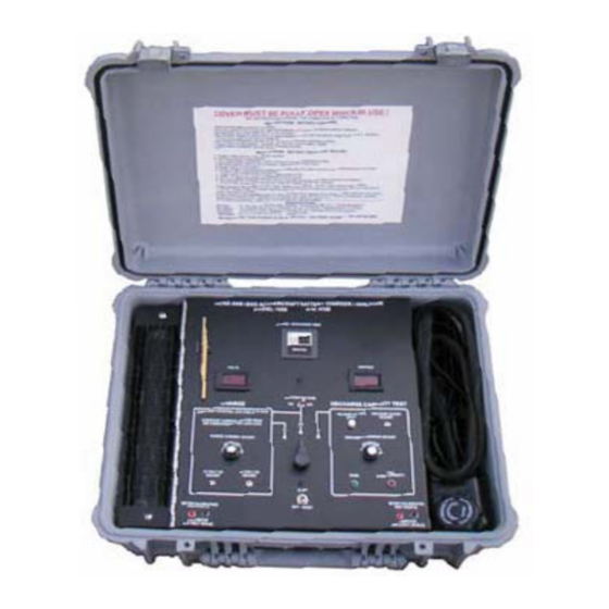
SYSTEM OVERVIEW Adjustment Tool Timer Voltmeter Ammeter Battery Voltage selector Voltage cutoff adjuster Voltage Cutoff View Discharge Current Adjust Charge/Discharge selector Pass/Fail Indicators Charge Current Adjust Mains On/Off/Reset Meter Calibration Test points 12 volt CP Adjust 24 Volt CP Adjust Figure 1-1. -
Page 6: Installation
2. INSTALLATION 2 INSTALLATION 2.1 LINE VOLTAGE The CA-1550-CML can operate on either 115 or 230 volts AC. The desired line voltage can be changed by opening the unit and modifying the voltage-set jumper(s). The unit is factory-preset at 115 volts AC. WARNING: Ensure that the unit is turned off and that no battery is connected before attempting to open the cover. -
Page 7: Terminals
2. INSTALLATION Connect the unit to a wall outlet with a 15-20 ampere capacity. Sharing of the line with other equipment may result in erratic operation if other equipment draws high pulse or surge currents. NOTE: The CA-1550 will maintain its operational integrity with line fluctuation up to ±... -
Page 8: Operating Guide - Charging
3. OPERATING GUIDE - CHARGING 3 OPERATING GUIDE - CHARGING 3.1 CHARGE CHARACTERISTICS The constant current charge characteristics of a lead-acid cell with respect to cell voltage, ampere-hours input, specific gravity and rate of gassing at constant current can be seen in Figure 3-1. Figure 3-1. -
Page 9: Charging Methods
3. OPERATING GUIDE - CHARGING acid batteries should never be charged in a constant-current mode with a current greater than C /10 (C equals the rated ampere-hour capacity of the battery). During constant current charging at a rate in excess of C /10, oxygen is produced at an excessive rate. -
Page 10: Preparation For Charging
3. OPERATING GUIDE - CHARGING The constant-current charge method can however be used for reconditioning SLABs. The current must be set low and the timer set to 12-18 hours. The battery should be periodically monitored for overheat during reconditioning. When the battery begins to accept charge current, it can be switched to constant-potential charging set to 14.5 (12 volt battery) or 28.6 volts (24 volt battery). - Page 11 3. OPERATING GUIDE - CHARGING A. SWITCH OFF MAINS POWER Turn off the AC on-off/reset power switch. B. TURN DOWN CHARGE CURRENT Repeatedly turn the Ampere Adjust knob fully counter-clockwise to set charge current to zero. Page 8 CA-1550 CHARGER / ANALYZER - OPERATING MANUAL LI-4159-CML Rev A...
-
Page 12: Charge Time
3. OPERATING GUIDE - CHARGING 3.4 CHARGE TIME 3.4.1 TIMER UNIT SETTING The CA-1550 has a built in timer, allowing charge time settings from 0.1- 999.9 minutes. 3.4.2 CHARGE TIME SETTING The charge time will be set based on the state of charge of the battery and at which rate the battery is being charged. - Page 13 3. OPERATING GUIDE - CHARGING E. MODIFY CONSTANT POTENTIAL If charging in constant-potential mode (CP), the constant charging voltage can be modified. This has to be done before connecting the battery. 1. Turn on the AC on-off/reset power switch. 2. Turn the Constant Potential Adjust Trimpot until the desired voltage is obtained.
- Page 14 3. OPERATING GUIDE - CHARGING H. SET CHARGE CURRENT 1. CONSTANT-CURRENT CHARGING Turn the Ampere Adjust knob until the desired charge current has been reached. The charge current is displayed on the ammeter as the current is being adjusted. CONSTANT-POTENTIAL CHARGING Turn the Ampere Adjust knob to max (fully clockwise) or to the desired current limit.
- Page 15 3. OPERATING GUIDE - CHARGING K. SWITCH AC POWER OFF Switch the AC on/off switch off before removing the battery. NOTE: If in emergency it is required to stop charging, switch the unit to off. When charging is restarted the timer is reset to zero. It may be necessary to adjust the parameters (current and time) before resuming charge.
-
Page 16: Operating Guide - Discharging
4. OPERATING GUIDE - DISCHARGING 4 OPERATING GUIDE - DISCHARGING 4.1 DISCHARGE CHARACTERISTICS The lead-acid and the nickel-cadmium cells are generally assigned nominal open circuit voltages of 2.10 volts and 1.35 volts respectively. Actual open circuit voltage at 75°F/ 25°C for a fully charged battery cell depends on state-of-charge and time after charge. - Page 17 4. OPERATING GUIDE - DISCHARGING 40 amperes. From Figure 4-1, it is observed that at the end of 1 hour of discharge time, the battery voltage has reduced only to about 22 volts. Because the minimum required cutoff voltage is 18 volts at the 1-hour discharge rate, the battery exceeds the minimum requirements.
-
Page 18: Discharge Capacity Testing
4. OPERATING GUIDE - DISCHARGING Figure 4-2. Typical discharge curves for SLABs at different rates The discharge of a lead-acid battery beyond the point of which exhaustion of the cell is approached can be harmful, as the battery will form a sulfate deposit on its plates. This is particularly true if the battery is not soon recharged. -
Page 19: Preparation For Testing
4. OPERATING GUIDE - DISCHARGING 4.2.1 Constant-Current Discharge Method The most accurate and repeatable method of measuring capacity is to discharge the battery at a constant-current rate. This is also the method used by the CA1550. The load resistance in this method is continuously and automatically varied to maintain a constant discharge current as the battery's voltage decreases. - Page 20 4. OPERATING GUIDE - DISCHARGING The battery must be fully charged before testing starts, except for special tests. WARNING: Always turn off the AC power switch before connecting or disconnecting a battery. NOTE: The test, unless otherwise specified in the manufacturer's CMM/OMM, shall be conducted at room ambient temperature of 70°F to 85°F (21°C to 29°C).
-
Page 21: Discharge Time
4. OPERATING GUIDE - DISCHARGING 4.4 DISCHARGE TIME 4.4.1 TIMER UNIT SETTING The CA-1550 has a built in timer, allowing discharge time settings from 1 to 999 minutes. 4.4.2 DISCHARGE TIME SETTING The discharge time is usually set to 60 minutes, after which a pass/reject signal is given based on whether the battery reached the cutoff voltage or not. - Page 22 4. OPERATING GUIDE - DISCHARGING 4.5.1 LEAD-ACID BATTERIES Always refer to your battery manufacturer's maintenance manual for the most accurate information. For a 24 volt sealed lead-acid battery the cutoff voltage is usually set at 18 or 20 volts when discharged one hour at a current equal to the 80% of the battery’s C 1-rate.
- Page 23 4. OPERATING GUIDE - DISCHARGING Table 4- 3. Discharge test setting for nickel-cadmium batteries 4.5.3 SETTING CUTOFF VOLTAGE ON THE CA-1550 Before setting the cutoff voltage, the unit must be turned on. F. SWITCH ON MAINS POWER Turn on the AC on-off/reset power switch. An audible alarm sounds, and the Accept lamp illuminates.
-
Page 24: Setting Discharge Current
4. OPERATING GUIDE - DISCHARGING G. VIEW AND SET CUTOFF VOLTAGE a. Press and hold the Voltage Cutoff View button. The set cutoff voltage is shown on the voltmeter display. b. Use a 1/16 inch (2 mm) slot blade precision type screw driver set the Voltage Cutoff Adjust to the desired level. -
Page 25: Test Completion And Analysis
4. OPERATING GUIDE - DISCHARGING 4.7 TEST COMPLETION AND ANALYSIS The CA-1550 automatically completes the test with the set parameters. However, it may be required to measure the individual cell voltages for nickel-cadmium batteries during the test (see section 4.7.2). WAIT FOR DISCHARGE TEST TO AUTOMATICALLY COMPLETE During the test the battery voltage, discharge current, and elapsed... - Page 26 4. OPERATING GUIDE - DISCHARGING 4.7.2 NICKEL-CADMIUM BATTERY Check each cell with a digital voltmeter near the end of the test. A. If no cells have dropped below 1.0 volts at the end of the specified time the battery has successfully completed the capacity test. B.
-
Page 27: Calibration And Maintenance
5. CALIBRATION AND MAINTENANCE 5 CALIBRATION AND MAINTENANCE 5.1 OVERVIEW OF CALIBRATION The CA-1550 has been calibrated before shipment from the manufacturer. A certificate of calibration has been issued and is enclosed in the back of this manual. To ensure error-free operation over time the unit should be re-calibrated every 12 months depending on usage and changes in surrounding environment. - Page 28 5. CALIBRATION AND MAINTENANCE for the calibration can be seen in Figure 5-1. The calibration steps are outlined below. Figure 5-1. Circuit diagram for voltmeter calibration A. SWITCH OFF MAINS POWER Turn off the AC on-off/reset power switch. B. SET LOW CHARGE CURRENT Repeatedly turn the Ampere Adjust knob fully counter-clockwise to set zero.
- Page 29 5. CALIBRATION AND MAINTENANCE C. SET TIMER Set the timer by pushing the up/down buttons to a time that will allow calibration to be completed before the time runs out (for example 60 minutes). D. SET CONSTANT-POTENTIAL CHARGE MODE Turn the Mode Select knob to Constant potential, CP.
- Page 30 5. CALIBRATION AND MAINTENANCE G. COMPARE VOLT READINGS Compare the CA-1550 digital voltmeter reading with the external calibrated voltmeter. a. If readings differ less than ± 0.2 volts, the voltmeter is accurately calibrated. Turn AC power off. b. If readings differ more than ± 0.2 volts, continue with steps I through K.
-
Page 31: Ammeter Calibration
5. CALIBRATION AND MAINTENANCE 5.3 AMMETER CALIBRATION To calibrate the CA-1550 ammeter, an external calibrated digital voltmeter, set to the millivolt range, is required as well as a discharged battery. The millivoltmeter will read the millivolts dropped across the CA-1550 internal shunt when a charge current is applied. - Page 32 5. CALIBRATION AND MAINTENANCE B. TURN DOWN CHARGE CURRENT Turn the 3-turn Ampere Adjust knob fully counter-clockwise to set charge current to zero. C. SET TIMER Set the timer by pushing the up/down buttons to a time that will allow calibration to be completed before the time runs out (for example 60 minutes).
- Page 33 5. CALIBRATION AND MAINTENANCE F. SWITCH ON MAINS POWER Turn on the AC on-off/reset power switch. The voltmeter reads battery terminal voltage, the ammeter reads zero. The timer reads 0000 and its red LED is off. The Charge Mode Lamp indicator is illuminated.
-
Page 34: Shunt Verification
5. CALIBRATION AND MAINTENANCE b. If readings differ more than ± 0.2 millivolts (amperes), continue with steps K through J. OPEN THE CA-1550 If voltmeter differs more than ± 0.2 millivolts (amperes), open the front panel of the CA-1550 by removing the two screws on the right side of the panel. WARNING: Calibration needs to be performed with the unit’s cover removed as well as both mains power and battery connected. -
Page 35: Discharge Current Operating Range
5. CALIBRATION AND MAINTENANCE EXTERNAL CALIBRATED MILLIVOLTMETER Figure 5-3. Circuit diagram for shunt verification 5.5 DISCHARGE CURRENT OPERATING RANGE The CA-1550’s factory preset max discharge rate of amperes can be increased past 50 amperes. If necessary to increase the discharge rate please contact the factory. 5.6 MAINTENANCE Standard electrical equipment maintenance and cleaning procedures should be followed. - Page 36 5. CALIBRATION AND MAINTENANCE The DC cable contains 4 leads. Two are heavy-gauge DC current leads for the battery discharge current. Two are light-gauge leads for sensing the battery voltage. Each current carrying lead has its sensing lead attached at the battery quick disconnect.
-
Page 37: Trouble-Shooting
6. TROUBLE-SHOOTING 6 TROUBLE-SHOOTING Problem Possible Cause Corrective Action A. Unit will not turn on The AC power is not connected Check AC line with voltmeter to unit Either AC line fuse is blown. Ensure correct AC line voltage May be due to incorrect AC line setting. - Page 38 6. TROUBLE-SHOOTING Problem Possible Cause Corrective Action Discharge current Reversed polarity of battery Ensure that polarity is respected immediately surges to a connection on battery connection. If high value and blows DC connector has been removed discharge fuses even ensure that DC leads are not though the current adjust reversed.
-
Page 39: Specifications
7. SPECIFICATIONS 7 SPECIFICATIONS 115 volts 10%, 50/60Hz, 14 amperes or AC Line Input: 230 volts 10%, 50/60 Hz, 7 amperes (selectable inside unit) 0 - 50 amperes adjustable current DC Discharge Current: Capacity 2% from discharge initiation to cut-off Accuracy Constant Current Capacity... -
Page 40: Warranty
(OEM), or original end user. If any product shall prove to be defective during the warranty period, LAMAR will repair or replace such part. -
Page 41: Certification Of Calibration
SERIAL NO: __________________ DATE OF MANUFACTURE:__________ VERIFIED BY: ________________ DATE OF VERIFICATION:___________ Lamar Technologies LLC certifies that the above listed CA-1550-CML Battery Charger /Discharger meets or exceeds all published specifications. Accuracies of calibration of instruments used are traceable to the National Institute of Standards and Technology. - Page 44 Designer and Manufacturer of Aircraft Lead-Acid and Nickel-Cadmium Battery Support Equipment Since 1980. Lamar Technologies LLC 14900 40 Ave NE Marysville, WA 98271 Cage Code: 3RCD2 Ph: (360) 651-8869 • Fax: (360) 651-6677 E-mail: admin@lamartech.com...
Need help?
Do you have a question about the CA-1550–CML and is the answer not in the manual?
Questions and answers