Table of Contents
Advertisement
Quick Links
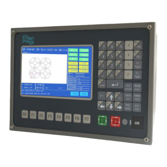
Model SH-2100AH-QG
(V5.0-1.0)
CNC
Cutting Machine
User's Manual
Contents
Functional Overview
Main Menu
AUTO
MAN
EDIT
Command System
SETUP
LIBMINIT
DIAGNOSE
I/O Interface
Appendix
1. Pin definitions of height controller
2. SH-2012AH-QG Software
Upgrading Instructions
3. Installation Dimensional Diagrams
4. Troubleshooting
5. Wiring Instructions of Extended
Manual Control Box
Advertisement
Table of Contents

Related Manuals for CNC SH-2100AH-QG

Summary of Contents for CNC SH-2100AH-QG
- Page 1 Contents Functional Overview Main Menu AUTO Model SH-2100AH-QG EDIT (V5.0-1.0) Command System SETUP Cutting Machine LIBMINIT DIAGNOSE I/O Interface Appendix User's Manual 1. Pin definitions of height controller 2. SH-2012AH-QG Software Upgrading Instructions 3. Installation Dimensional Diagrams 4. Troubleshooting 5. Wiring Instructions of Extended...
- Page 2 All rights reserved Forbidden to distribute or duplicate any file for the purpose of commercial, communication or others without particular authorization. Compensation will be incurred if any clause is violated. All rights belong to Beijing Starfire Control Technology Co., Ltd. Disclaimer We have made a consistency inspection to the contents of the printed file against the product described.
- Page 3 5. Make sure the CNC is correctly wired and securely grounded. 6. Never try to hot plug/unplug any cable on the rear panel of the CNC, for the damage incurred thereby is beyond our quality warranty. 7. No cable from the output port of the rear panel should be shorted with any power cable; otherwise, the CNC might be burned.
-
Page 4: Table Of Contents
Chapter I. Functional Overview ................................... 1 1.1. System Functions ................................... 1 1.2Technical specifications ................................... 1 1.3Starfire also supplies the following auxiliary products for compact CNC cutting machine............... 2 Chapter II. Main Menu ....................................3 2.1. Menu Features ....................................3 2.2. - Page 5 Appendix I: The Wiring Diagram and Pin Definitions for Model SH-HC30 Height Controller Manufactured by Starfire ....42 Appendix II: Instructions for Software Upgrading Operation of SH-2012AH ..................44 Appendix III: Installation Dimensional Drawing ............................. 45 Appendix IV: Troubleshooting ................................... 46 Appendix V: Wiring Instructions for Extended External Manual Control Box ..................49 Model SH-2100AH-QG Cutting Machine(C002)...
-
Page 6: Chapter I. Functional Overview
Chapter I. Functional Overview 1.1. System Functions Model SH-2012AH-QG CNC System for Cuttingis designed to work with torch/plasma, high-pressure water jet and laser cutting machines and extensively used in metal working, advertisement fabrication and stone machining businesses. High reliability as well as good resistance to plasma disturbance, lightning and surge. -
Page 7: Starfire Also Supplies The Following Auxiliary Products For Compact Cnc Cutting Machine
1.3Starfire also supplies the following auxiliary products for compact CNC cutting machine. Model SH-2012AH-QG Cutting Machine(C002)... -
Page 8: Chapter Ii. Main Menu
Chapter II. Main Menu 2.1. Menu Features The design of hierarchy-based functional windows is adopted for system operating display. If a function is invoked in the main menu window, the corresponding subwindow menu will pop up. Press [F1] to [ F7] to select the corresponding function according to window prompt. -
Page 9: Chapter Iii. Automatic Function(Auto)
Chapter III. Automatic Function(AUTO) In the main menu, press [F1] to enter the automatic function window, as shown in the figure below. Piercing Hole No. Kerf Active speed multiplying Program name factor Heavy-current control output Pattern Function keys Display Space Input/output Coordinates indication... -
Page 10: Description Of Automatic Mode Window
3.1. Description of Automatic Mode Window 3.1.1 SPEED In automatic mode, at the top left corner of the screen, it shows F× (multiplying factor of automatic machining speed)= set machining speed. In manual mode, at the top left corner of the screen, it shows F× (multiplying factor of manual speed)=manual speed. SPEED indicates the actual speed while the active speed multiplying factor is adjustable with [F↑] and [F↓]. -
Page 11: Function Selection In Auto Mode
Plasma machining case: execute M07 command. Note: This is a very important feature. It will be used repeatedly in pause, return and extend piercing operations. When preheat is done, pressing [PIERCE] key will start up piercing operation directly. [SWOFF]: To shut off all the heavy-current output. [S↑]: Push it down to rise the cutting torch and release to stop the torch. - Page 12 This key is used to reminder input of kerf compensating width; if no necessary to compensate(usually in blanking), simply enter 0. 3.2.6[F6] ASSI This key is used to enter the next lower level of menu, as shown in Fig. 3.2 below. Fig.
-
Page 13: Startup Of Speed Mode(Multiplying Factor) And Automatic Mode
3.2.9 [F5] SCALE The system will reminder user to input scale if this key is pressed. When the machining program is executed, the work size will magnify or minify as per this scale. This feature is very useful in cutting graphic character. 3.2.10 [F2] WENTAI The system will prompt to run WENTAI-based machining program if this key is pressed. - Page 14 4) [Emergency Stop] key: It is an external key with signal received from the input port(refer to "External Input Ports" for details). If emergency stop is validated, all the movement will stop and no output will go on. It is used for emergency case.
-
Page 15: Original Path Return
It is recommended to preheat the system(for flame cutting) and then press [START] key to select appropriate operation. 3.5. Original Path Return When it is necessary to return the cutting torch along the original path due to failure to cut through in machining operation, handle it in the following ways: 3.5.1Return along original path Press [PAUSE] key to suspend the running system. -
Page 16: Breakpoint Restoration Process
3.6. Breakpoint Restoration Process 3.6.1.Breakpoint restoration In case of manual pause or power outage in machining operation, the system will automatically save the current position of cutting torch as a breakpoint, which will be kept permanently in the system, whether power the system off or not. -
Page 17: Move Hole For Thick Plate
Fig. 3.5 SECTION function menu Move the cursor with [↑] or [↓] key and make one choice from two machining options. According to your option, the system will prompt to input the serial number of the option(program line number or the serial number of piercing point). - Page 18 Fig. 3.7 Option dialog box prompted by the system after reach piercing point if edge piercing method is selected 3.8.1HOLE To pierce at the original position, which is often used for boring. 3.8.2MOVE HOLE 1) Operator may press [↑], [↓], [←] and/or [→] key to move the cutting torch to the edge of steel plate; in the mean time, the speed multiplying factor is adjusted to 5% automatically.
-
Page 19: Chapter Iv. Man(Manual Mode)
Chapter IV. MAN(Manual Mode) In main menu, press [F2] to enter MAN (manual) window, as shown in figure below: Active speed Program name Piercing No. Kerf Heavy-current control output multiplying factor Pattern Display Function keys Space Input/output indication Workmode indicating Coordinates zone Machining... - Page 20 manual mode as follows: [↑], [↓], [←], [→] directional control keys and [G] Continue Key 4.1.1 Generally, if any of the four direction keys is pressed and held, appropriate axial movement will carry on until the key is released. However, if [G] Continue key is pressed and highlighted before any direction key is pressed, the cutting torch will keep moving even if the key is released.
-
Page 21: Chapter V. Edit Mode
Chapter V. EDIT Mode In the system main menu, press [F3] to enter EDIT menu as shown in the figure below: PROG S/N PROG editing area Esc key Fig. 5.1 EDIT menu window 5.1. Description of EDIT Menu Main menu of EDIT 5.1.1【F1】NEW To establish a new program, i.e., clear the editing area of machining program and start to edit a new machining program. - Page 22 5.1.5. 【F5】DELL To delete a full program line in editing area and improve editing efficiency. 5.1.6. 【F6】TRAN To transmit programs. This system supports to transmit programs with USB disk. Press [F6] key to enter the lower level of menu, as shown below. : Fig.
-
Page 23: Chapter Vi. Command System
Chapter VI. Command System 6.1. Description of Programing Symbols In CNC cutting operation, each step is taken according to a program. Each machining program is composed of several command segments, each command segment is composed of several function words and each function word is required to be a letter followed by parameter value. -
Page 24: G: Basic Preparatory Commands
6.3. G: Basic Preparatory Commands 1) G92: Reference Point Setting Command When developing a program, it is required to place the coordinate value(absolute coordinate) of machining origin point(reference point) at the very beginning. Format: G92 Xn Yn If G92 is not followed with X/Y coordinate values, then the current X/Y coordinate will be taken as reference point. Generally, when the origin point of machine is used as reference point for positioning purpose, G92 will not be followed with X/Z values. - Page 25 G00 Quick Move 4) This command can move the cutting torch quickly to a designated position. In the event of two axial movements, the cutting torch will move along a straight line from the origin point to the end point at the speed of the maximum speed limit multiplied by multiplying factor.
- Page 26 例(G02): G92 X0 Y0 O’ G00 X40 Y50 G02 X160 V0 I60 J20 +100 +160 Current Torch Position 例(G03): Expected Torch Position G92 X0 Y0 Notes: G00 X40 Y50 I and J are the increased values of circle center relative to the origin point in X-axis and Y-axis respectively(distance betwen the circle center and the origin point).
- Page 27 5 levels. G22 and the nearest G80 form a loop. (L to designate number of cycles) Format: G22 Ln_ Loop (End mark of loop) Example: N000 G92 X100 Y100 N001 G00 X60 Y80 N002 G22 L5 - Level 1 loop starts. N003 G00 V50 U-25 N004 G22 L5 - Level 2 loop starts.
-
Page 28: M Auxiliary Commands
6.4. M Auxiliary Commands Program suspension command. The program execution will be suspended at this command until [START] key is pressed. Program end command. The program will be pended at this command. The same as M02. M10/M11 Acetylene(GAS) valve switch commands, M10 to open and M11 to close the valve. M12/M13 Cutting oxygen valve switch commands, M12 to open and M13 to close the valve. - Page 29 2.Turn off the height controller(M39). 3.Lift the cutting torch(M70). The operation sequence of M08 in plasma cutting operation is as follows: 1. Turn off the arc voltage switch. 2. Turn off the height controller(M39). 3. Lift the cutting torch(M70). M50: Piercing action 1....
-
Page 30: Chapter Vii. Setup(Parameter Setting)
All the output ports will be turned off if the command of M80 is executed. Chapter VII. SETUP(Parameter Setting) In the system main menu, press [F4] to enter parameter setting window as shown below: ESC key Fig. 7.1 SETUP main menu SETUP main menu 7.1. -
Page 31: Setup(Parameter Setting)
Notes: When selecting the above parameters, it is required to save the change separately by pressing [F8] key for validation. If the password of "1928" is entered in the main window of SETUP, the saving menu of [F8] will turn to factory setting. - Page 32 Parameters display zone Parameter setting range SETUP main menu ESC key Fig. 7.2 Speed parameters setting 8) Circular corner transitional radius ---- Refer to circular corner transitional option. 7.2.2. System parameters In the SETUP submenu, press [F2] key to enter system parameters setting window, as shown in Fig. 7.3. Parameters display zone Parameter...
-
Page 33: Flame Cutting Parameters
the measured value into the following formula: Numerator X Actual Travel Distance Denominator X Theoretical Travel Distance Simplify the above formula to a fraction in lowest terms. E.,g., assume the electronic gear ratio is 8:1 and the theoretical travel distance is 2000mm and the actual travel distance is 2651 8 X 2651 2651 Mechanical origin ---- A special point on the machine set with proximity switch. -
Page 34: Plasma Parameters Setting
auxiliary commands. Lifting delay of piercing torch——The time delay when M72 command is executed, in second. Refer to 6.4 for M auxiliary commands. Lowering delay of piercing torch——The time delay when M73 command is executed, in second. Refer to 6.4 for M auxiliary commands. -
Page 35: Control Parameters Setting
Parameters Parameter display zone setting range Remarks SETUP main zone menu ESC key Fig.7.5 Plasma Parameters Setting 7.5. Control Parameters Setting In the SETUP submenu, press [F5] key to enter control parameters setting window, as shown in Fig. 7.6 Parameters display Parameter setting zone... -
Page 36: Control Parameters Setting Of Height Controller
axis) shares a common edge with X axis or with Y axis for the machine requiring double-edge drive. Take 0 to have Z axis and X axis share a common edge; take 1 to have Z axis and Y axis share a common edge. Metric/English system option ——Take 0 for metric system, which will have length parameters, speed parameters and values as well as coordinates expressed in metric unit(mm), though it supports machining program in English system(G20). -
Page 37: Chapter Viii. Libminit(Library Of Patterns)
Chapter VIII. LIBMINIT(Library of Patterns) 8.1. LIBMINIT Setting In addition to customized pattern module, the feature allows user to input the intended dimensions and get the expected workpiece. When entering parameter, the control system will conduct general check to the physical dimensions and prompt warning message if any error is detected. -
Page 38: Arrangement And Layout Of Pattern Element
8.3. Arrangement and Layout of Pattern Element After pattern element is selected as per the above-mentioned procedure, the system will prompt at the upper right corner to input parameters for the pattern, as show in Fig. 8.2 【F1】Workpiece: To machine into workpiece that is solid internally. 【F2】Hole: To machine into hole that is solid externally. -
Page 39: User Defined Module
【F8】Submit: After parameters are set, press this key to generate machining program. 8.4. User Defined Module User is allowed to customize module with the following method . Firstly, it is required to edit a standard program for the self-defined module and name it as TK17S.NC, which should have the following structure: G92 X0 Y0 // User-defined module, Note: The original program should not have more than 59 lines. -
Page 40: Chapter Iv. Diagnose
Chapter IV. Diagnose In the system main menu, press [F5] to enter DIAGNIZE main window, as shown in the figure below: Output port Output state Input port Input state In Plasma Operation In Flame Operation Check Input/output Ports The system diagnosis will show the hardware resources available. In DIAGNOSE window, it is allowed to check the state of input/output port. -
Page 41: Chapter X. Connections Of Input/Output Ports
10.1. System Input Principle Generally, mechanical switch is used for travel limit/start/pause. To shield the system from interference, normally-closed contact is usually used for mechanical switch, which is connected with the way described below. Load Internal CNC System COM(+24V) Intermed iate relay 24VGND... -
Page 42: Definitions Of Input/Output Ports
10.3 Definitions of Input/Output Ports Signal 25-pin Description definition port(socket) X/Y+ limits, two positive axial travel limits connected in series, high priority. Please jump the >W+ signal to 24V ground if not use. X/Y-limits, two negative axial travel limits connected in series, high priority. Please W-<... -
Page 43: Definitions Of 15-Pin Ports For Motor
10.4 Definitions of 15-pin Ports for Motor 1.Differential Signal 2.Common Anode Connection XDIR XDIR+ XDIR- XCP+ XCP- YDIR YDIR+ YDIR- YCP+ YCP- X/YDIR X/YDIR+ 辅助 X/YDIR- X/YCP X/YCP+ 辅助 OPTO X/YCP- 5V common 10.5 Typical Wiring for Flame Cutting Operation(DB15) Cutting oxygen solenoid valve Gas/preheating oxygen solenoid valve DC24V... -
Page 44: Typical Wiring For Plasma Arc Cutting Operation
10.6 Typical Wiring for Plasma Arc Cutting Operation Input/output(DB25) X+ limit Y+ limit Input end Output end X- limit Y- limit External start key External backspace key To height controller/successful plasma arc ignition signal Emergency stop(NC contact) External pause key(NC contact) Initial location of torch Auto/manual switch for output M38 height controller in plasma mode(corner signal) -
Page 45: Pin Definitions
10.7 Compatible Connection for Flame/plasma Operations When the system is required to connect both plasma and flame cutting torches, make the connections for plasma mode and flame mode respectively as described above and then provide a flame/plasma selective switch K1 with the connection method as shown in the diagram below. - Page 46 2.Pin Definitions of XS8 for System Communication/Manual Control (DB15) Definitions Description Remarks 24V power supply RS232 transmission RS232 receive Ground for 24V power supply Input Port 9 for External Control Box X+ Input Port 10 for External Control Box X- Input Port 11 for External Control Box Y+ Input Port 12 for External Control Box Y- Input Port 13 for piercing key of External...
-
Page 47: Appendix I: The Wiring Diagram And Pin Definitions For Model Sh-Hc30 Height Controller Manufactured By Starfire
1. Hybrid Wiring Diagram Compatible with Both Arc Voltage Type and Capacitance Type 9-pin connector of divider board 15-pin connector for 25-pin connector for height controller CNC system Pin Definitions List of 9 Pin Connector for Divider Board Attribute Description Power supply Ground of 24V power supply for height controller... - Page 48 3. Wiring Diagram of Arc-voltage-type Height Controller 9-pin connector of divider board 调高控制器 15 芯接头 25-pin connector for CNC 15-pin connector for system height controller 4.Wiring Diagram of Capacitance-type Height Controller 15-pin connector for 25-pin connector for height controller CNC system Model SH-2012AH-QG Cutting Machine(C002)...
-
Page 49: Appendix Ii: Instructions For Software Upgrading Operation Of Sh-2012Ah
Appendix II: Instructions for Software Upgrading Operation of SH-2012AH Functions: The system software is allowed to upgrade through an USB disk. The specific operation procedure is as follows: 1.File upgrading Copy the upgrading file titled STARTCNC.EXE to an USB disk. 2.Operation procedure Push and hold the button between the red button 0 and the USB port. -
Page 50: Appendix Iii: Installation Dimensional Drawing
Appendix III: Installation Dimensional Drawing Model SH-2012AH-QG Cutting Machine(C002)... -
Page 51: Appendix Iv: Troubleshooting
CNC software at fault The system still runs but a The travel motor is lock Check if the machine is frozen and le the cutting torch stops ab vel enough. - Page 52 If no external limit switch Modify it to normal range. is connected, check the s ystem if the current coordi nate values are too high a nd out of the travel limit set by software. Check if the travel limit set by soft ware is too small.
- Page 53 The power supply unit for plasma, CNC system and the enclosure of machine must shar e a ground wire that is 2mm thick at least in diameter and well connected to the ground.
-
Page 54: Appendix V: Wiring Instructions For Extended External Manual Control Box
Appendix V: Wiring Instructions for Extended External Manual Control Box The system is allowed to connect a handheld (or wireless) external control box through 8 input ports. The wiring instructions are as follows: (DB25) Input/output XS12 Start key Pause key Emergency stop key Backspace key X-axis positive movement...
Need help?
Do you have a question about the SH-2100AH-QG and is the answer not in the manual?
Questions and answers