Advertisement
Quick Links
SERENITY CEDAR PERGOLA KIT
FREESTANDING
ASSEMBLY MANUAL
| 1
P a g e
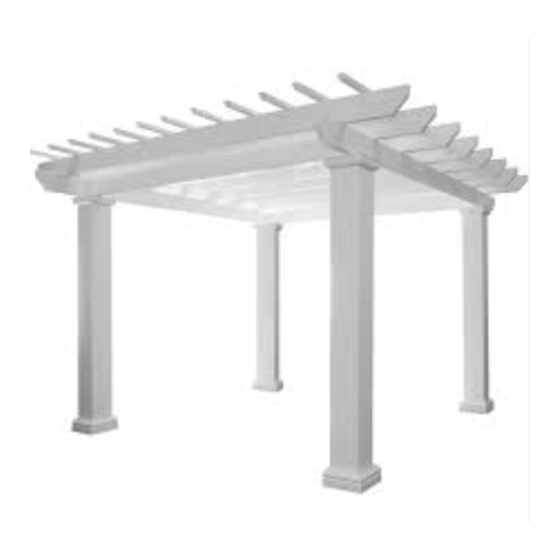
WOOD 4 BEAM PERGOLA INSTRUCTIONS
Shown – 10'x14' Serenity Cedar Pergola Kit
Thank you for purchasing the 4 Beam Wood Pergola. Depending on the size of the
pergola, installation can usually be completed in a day. These instructions apply to both
cedar and treated pine models.
Consider a few details before starting assembly:
1. The base for the pergola must be solid and level. If installing on a concrete slab or
on concrete footers, it should be level where the posts will rest. If not, it may be
Advertisement

Related Manuals for Pergola kits USA SERENITY

Summary of Contents for Pergola kits USA SERENITY
- Page 1 P a g e WOOD 4 BEAM PERGOLA INSTRUCTIONS Shown – 10’x14’ Serenity Cedar Pergola Kit Thank you for purchasing the 4 Beam Wood Pergola. Depending on the size of the pergola, installation can usually be completed in a day. These instructions apply to both cedar and treated pine models.
- Page 2 Thank you for purchasing the 4 Beam Wood Pergola. Depending on the size of the pergola, installation can usually be completed in a day. These instructions apply to both cedar and treated pine models. There are a few things you should consider before installation: 1.) Do not store the Pergola components in direct contact with ground concrete, or other moisture wicking surface as this may warp the components.
-
Page 3: Section One - Posts
them so that they are positioned in the used to ma them so that they are positioned in the used to m approximate location of where the pergola the 2x4 boa approximate location of where the perg the 2x4 b will be. - Page 4 dimensions MUST be the same. Adjust the tem pergola to a wood deck, use a 4” lag bolt (not included) instead of a wedge bol until the diagonal measurements are identical. 5. Once the template is “square”, mark the pos locations using the INSIDE corners of the frame on a concrete slab with a pencil.
- Page 5 Setting the Posts Post Bases 7.) Attach all the posts to the bracket using (5) 8.) Now you are ready to install the Post Bases. Get a ladder and slide the base over the top 2-1/2” screws per bracket. of the post (see picture above). There are (6) screws per base, it does not really matter which way they are turned, although we recommend keeping the screws turned in the same...
- Page 6 Install Headers Install the Top Plate 9.) Now you are ready to install the headers. 10.) The top plate is a piece of 2’ x 8’ wood that is precut to fit on top of the beams. Rest all 4 It does not matter which side you start on.
- Page 7 Anchor remaining Posts to Concrete NOTE: On larger pergolas, your top plates will be spliced, just match the letters together and 13.) Sliding the base up towards the top you continue with the step. can fasten it to the post with a screw to keep it from falling down.
-
Page 8: Section Two - Main Runners
ON 3 – MAIN RUNNERS n runners are 2x6’s that have decorative cuts on both ends (unless a They have markings on the top for the top runners. SECTION TWO – MAIN RUNNERS out spacing: Generally both the main and top runners are spaced 16” on The main runners are 2’x6’s that have decorative cuts on both ends (unless a special order). - Page 9 nners are set about ¼” from the edge of the runners. Do ners. Do this for the Most importantly, the top runners de. Never change the placement of the er to the end of the top plate. Set the first runner. Next, unners.
- Page 10 4. Double Check Spacing: Double check spacing by using two of the top er the l of the runners are in place and attached runners. Set each on the main runners and make sure that the notches in th ngs are top runners slide down over the main runners.
-
Page 11: Finishing Touches
from one side of the pergola to the next in order to make sure that any bows in un Additional Screw: Once all of the runners are in place and attached runners are worked out. Attach the top 2x4 runners onto the main runners usin screws from the top through the pre drilled holes.
Need help?
Do you have a question about the SERENITY and is the answer not in the manual?
Questions and answers