Table of Contents
Advertisement
Quick Links
Advertisement
Table of Contents

Related Manuals for Automation Technology MCS 1280 Series


Summary of Contents for Automation Technology MCS 1280 Series
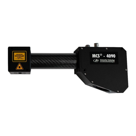
- Page 1 MCS Manual Rev. 1.4 User Manual for: MCS cx1280 MCS cx2040 MCS cx4090...
-
Page 3: Table Of Contents
Table of Contents TABLE OF CONTENTS ......................1 GENERAL NOTES ......................... 4 Copyright ............................... 4 Disclaimer ..............................4 Trademarks ..............................4 Symbols and Notes ............................5 Maintenance Instructions ..........................6 Cleaning ................................6 LASER SAFETY ........................7 Laser Safety Classification ........................... 7 Laser Categories ............................ - Page 4 Sensor Algorithms ............................29 Image Mode (IMG) ............................29 Maximum Intensity Profile Mode (MAX) ....................... 30 Threshold Mode (TRSH) ..........................31 Center Of Gravity Mode (COG)........................32 FIR Peak Mode (FIR PEAK) ..........................33 FIR Filter Function ............................34 Subpixel Limitations ..........................35 High Dynamic Range 3D Feature (HDR-3D) ....................
- Page 5 Cables for Power, I/O and Laser Control ....................... 71 Wire Assignment of M12 17 pin Pigtail Cable ..................... 72 Cables for GigE Interface ..........................73 Orientation of Angled Adapter Cable ......................75 GenICam Features ............................76 Device Control ..............................76 Image Format Control .............................
-
Page 6: General Notes
Neither is any liability assumed for damages resulting from the use of the information contained herein. No license is granted under any patents or patent right of AT - Automation Technology GmbH. Trademarks All nationally and internationally recognized trademarks and trade names are hereby acknowledged. -
Page 7: Symbols And Notes
Symbols and Notes The following general safety rules must be taken into account during installation, operation and maintenance. Failure to do so may cause damage to the operator, the sensor or the environment. Warning • Do not use the sensor in adverse environmental conditions, such as in rooms with a high concentration of flammable gases, vapors or dust. -
Page 8: Maintenance Instructions
Maintenance Instructions Cleaning The sensor is maintenance-free. This chapter is limited to cleaning the sensor. Use only the following items: • Water • Residue-free, weak detergent solution • Soft cloth • Lens cleaner liquid or 96% ethyl alcohol • Lens cleaning cloths Clean the sensor with the wetted, non-dripping cloth. -
Page 9: Laser Safety
Laser Safety Automation Technology´s compact sensor series have an integrated laser (Laser = Light Amplification by the Stimulated Emission of Radiation) module, which has to incorporate additional safety features, depending on the applicable laser class. Laser Safety Classification The International Electrotechnical Commission (IEC) and the U.S. Center for Devices & Radiological Health (CDRH) enforce strict safety requirements for lasers and laser products. -
Page 10: Class 2M
Class 2M Class II/2M lasers are visible low power lasers limited to 1 mW continuous wave or more due to the eye blink reflex for emission duration less than 0.25 seconds. Considered eye-safe with caution but may present a greater hazard if viewed using collecting optics. -
Page 11: Class 3B
Class 3B Class IIIb/3B lasers are medium power laser sources above 5mW up to 500 mW. Considered dangerous to your retina if exposed. Normally class IIIb/3B lasers will not produce a hazardous diffuse reflection. Viewing into the reflection should not exceed exposure duration more than 10 seconds Class IIIb/3B laser products must bear warning and certification labels. -
Page 12: Laser Responsibilities
Laser Responsibilities Requirement Class 2M Class 3R Class 3B System Interlock Not required Not required Required Warning Signs Not required Required Required Emission Indicator Not required Not required Required Laser Safety Officer Not required Required Required Key Control Not required Not required Required –... -
Page 13: Mcs Overview
MCS Overview Introduction The MCS series is a revolutionary product family of intelligent high speed laser triangulation sensors. It is optimised for 3D profile measurement by means of laser triangulation technique. The 3D profile extraction is performed in the sensor by using high performance Field Programmable Gate Array processors. -
Page 14: Mcs 1280, 2040 And 4090 General Specifications
MCS 1280, 2040 and 4090 General Specifications Sensor Controls Synchronization Modes Free Running, Triggered, Software Triggered Exposure Modes Programmable, Pulse Controlled Shutter Modes Global Shutter 2 electrical isolated inputs, +5V to +24V DC Digital Input VIL, logic “0” Voltage < 1.5V VIH, logic “1”... - Page 15 GigE Vision with GenICam Communication Protocol Mechanical Interface Power Connector 17 pin, M12 connector 8 pin, A-coded M12 connector Ethernet Connector Mechanical Stress Specification Vibration (sinusoidal each axis) 2g, 20 to 500Hz IEC 60068-2-6 Vibration (random each axis) 5g, 5 to 1000Hz IEC 60068-2-64 Shock (each axis) IEC 60068-2-27...
-
Page 16: Mcs Sensor Specifications
MCS Sensor Specifications Sensor Specifications Parameters CMOS Sensor Type Global Shutter Shutter Type 4096 x 3072 1280x1024 2048 x 1088 Resolution (Row x Column) in Pixel 10 Bit 12 Bit Sensor ADC Resolution 90dB with HDR Sensor Dynamic Range 10 W 10 W Max. -
Page 17: Sensors Spectral Response
Sensors Spectral Response SPECTRAL RESPONSE cx1280 cx2040 cx4090 1000 WAVELENGTH [nm] MCS Manual Rev. 1.4... -
Page 18: Temperature Range (Operation/Storage)
Temperature Range (Operation/Storage) Housing temperature during operation: 0°C to +50°C (+32°F to +122°F) FPGA temperature (Mainboard) during operation: 0°C to +60°C (+32°F to +140°F) Humidity during operation: 20 % to 80 %, relative, non-condensing Storage temperature: -20°C to +80°C (-4°F to +176°F) Storage humidity: 20 % to 80 %, relative, non-condensing The temperature affects the lifetime of the MCS device. -
Page 19: Definition Working Distance And Field Of View (Fov)
Definition Working Distance and Field of View (FOV) Definition Coordinate System MCS Manual Rev. 1.4... -
Page 20: Mechanical Drawings
Mechanical Drawings Housing Types MCS Manual Rev. 1.4... - Page 21 Dimensions Housing Type 1 and 2 All dimensions in mm MCS Manual Rev. 1.4...
- Page 22 A (Spacer) 15,5 30,5 45,5 60,6 80,5 All dimensions in mm MCS Manual Rev. 1.4...
- Page 23 Housing Type 3 All dimensions in mm MCS Manual Rev. 1.4...
- Page 24 Recommended mounting position 1. Alternatively, position 2 or position 3 can be used separately for mounting. WARNING: Mounting on multiple positions is not recommended and may affect the calibration accuracy! All dimensions in mm MCS Manual Rev. 1.4...
- Page 25 Housing Type 4 and 5 All dimensions in mm Height and window position of sensor module varies depending on the triangulation angle. MCS Manual Rev. 1.4...
- Page 26 A (Spacer) 107,5 12,4 122,5 27,4 137,5 42,4 152,5 57,4 172,5 77,4 All dimensions in mm MCS Manual Rev. 1.4...
- Page 27 Housing Type 6 All dimensions in mm Height and window position of sensor module varies depending on the triangulation angle. MCS Manual Rev. 1.4...
- Page 28 Recommended mounting position 1. Alternatively, position 2 or position 3 can be used separately for mounting. WARNING: Mounting on multiple positions is not recommended and may affect the calibration accuracy! All dimensions in mm MCS Manual Rev. 1.4...
-
Page 29: Laser Mtbf (Mean Time Between Failures)
Laser MTBF (Mean Time Between Failures) The laser MTBF describes the expected time between failures of a laser during operation. The described MTBF values are for an environment temperature of 25°C. Higher temperatures will reduce the laser lifetime. Part Number # Description MTBF @25°C (h) 50000... -
Page 30: Operational Reference
Operational Reference Measuring Principle The sensor acquires height profiles and height images based on the laser triangulation principle. According to this method a laser line is projected on the object from one direction. The imager sensor views the object from another angle defining the triangulation geometry. The resulting sensor image is evaluated by the embedded processor and converted into a single height profile. -
Page 31: Sensor Algorithms
Sensor Algorithms The compact sensor can be operated both - in a variety of 3D profile modes and in image mode. The current operation mode can be chosen by setting the parameter Camera Controls→ ModeAndAlgorithmControls→CameraMode. The frame rate can be increased in all camera modes by reducing the AOI size. In the image mode the frame rate is limited by the output rate of the camera interface (GigE). -
Page 32: Maximum Intensity Profile Mode (Max)
Maximum Intensity Profile Mode (MAX) In this mode the position of the maximum intensity of laser beam profile is calculated. The result includes the position value of the maximum (P ) as well as the maximum intensity value (I AO I_TRSH The calculation of position value is performed with simple pixel accuracy, i.e. -
Page 33: Threshold Mode (Trsh)
Threshold Mode (TRSH) In this mode the position of left (P ) and right (P ) edge of the laser beam profile are detected for a given threshold value of intensity AOI_TRSH. AO I_TRSH TRSH The position value of the laser line is approximated: P = (P ) / 2. -
Page 34: Center Of Gravity Mode (Cog)
Center Of Gravity Mode (COG) In this mode the center of gravity of laser beam profile is calculated. For this purpose, the following parameters are computed: Position value of the left edge of laser beam profile for a given intensity threshold value P Sum of intensity value I = ∑... -
Page 35: Fir Peak Mode (Fir Peak)
FIR Peak Mode (FIR PEAK) In this mode the first derivative of the intensity Gauss curve of laser beam profile is calculated. 1023 1023 First Derivative Intensity of Intensity AOI_TRSH AOI_TRSH Zero-Crossing AoiHeight AoiHeight Sensor row # Sensor row # The position of zero-crossing of first derivative is detected and output with subpixel accuracy (up to 6 subpixel). -
Page 36: Fir Filter Function
FIR Filter Function The FIR filter is a signal processing function aiming to increase the precision of laser line detection in the sensor image. It consists of a digital Finite Impulse Response filter (FIR) and can be operated in a smoothing or differentiating mode. FIR in smoothing mode (in combination with MAX, TRSH and COG algorithms): Raw Gauss Curve Smoothed Gauss Curve... -
Page 37: Subpixel Limitations
Subpixel Limitations The range values of the 3D sensors are limited to 16bit which result to possible values between 0 and 65535. Setting the subpixel value to 6 correspond to a factor of 2^6 = 64. If the laser line appears at a sensor row higher than #1023 (with 6 subpixel) will result in a bit overflow. -
Page 38: High Dynamic Range 3D Feature (Hdr-3D)
High Dynamic Range 3D Feature (HDR-3D) One of the most powerful features of AT´s camera is the HDR-3D (High Dynamic Range) functionality, which allows scanning materials and surfaces with inhomogeneous reflection properties. Using HDR-3D the dynamic range of image intensity is extended up to 90dB, thus avoiding intensity saturation. - Page 39 Single Slope Mode (Default Mode) Intensity Saturation 100% Exposure Time Weld Seam Dual Slope Mode (1 Knee Point) Intensity Knee Point 1 Saturation 100% Saturation Threshold 1 Exposure Exposure Limit 1 Time Weld Seam Triple Slope Mode (2 Knee Points) Intensity Knee Point 2 Knee Point 1...
- Page 40 Comparison of Slope Modes Application of MultipleSlope function on the image of a laser line projected on a surface with non-homogeneous reflectivity (weld seam). SingleSlope DualSlope TripleSlope 1100 1100 1100 1000 1000 1000 Sensor row # Sensor row # Sensor row # More details regarding the operation of the MultipleSlope function can be found in a separate application note.
-
Page 41: Multi-Frame Readout Mode (Ndr)
Multi-Frame Readout Mode (NDR) With the Non-Destructive Readout (NDR) mode it is possible to readout up to 4 images at different exposure times. It allows the combination of profile data from different integration levels and it ensures accurate profile data even for difficult surfaces with strong changes in reflectance. The following timing diagram shows the function of NDR with 2 frames, when subsequent sensor images are acquired. -
Page 42: Data Output Format
Data Output Format The image and 3D data output is performed by selecting the data channel DC0-DC2 (node Camera Controls→DataOutput). Depending on the algorithm the data can be acquired by enabling the corresponding output Data Channel (DC). Every DC is saved in a new image row. The bit depth of output data depends on the selected algorithm. - Page 43 FIRMode Camera Mode detected in smoothed sensor Gauss width (PosR-PosL) image detected in smoothed sensor image False Sum of intensity values of Position of center of gravity of Position of rising edge of Gauss CenterOfGravity Gauss I Gauss with 1/(2 ) pixel resolution, (PosL) where N=number of subpixel bits...
-
Page 44: Output Frame Structure
Output Frame Structure Depending on configuration, the sensor writes data to the output frame according to following scheme: 1) NDR mode disabled (NDRMode=”Off”) for(profile_idx=1; profile_idx <=ProfilesPerFrame; profile_idx ++) for(AOI_idx=1; AOI_idx<=NumAOIs; AOI_idx++) if(EnableDC0==true) write_data_of_DC0(AOI_idx); if(EnableDC1==true) write_data_of_DC1(AOI_idx); if(EnableDC2==true) write_data_of_DC2(AOI_idx); 2) NDR mode enabled (NDRMode=”On”) for (profile_idx=1;... - Page 45 Index Definition Index # Range Description Profile_idx 1-17475 Index of Profile AOI_idx Index of sensor AOI NDR_idx Index of NDR frame Examples of Output Frame Structure 1) Configuration with single AOI, single DC, disabled NDR mode and output of 6 profiles resulting to a frame height of 6 rows: ProfilesPerFrame NumAOIs...
- Page 46 2) Configuration with two AOIs, two DCs, disabled NDR mode and output of 5 profiles resulting to frame height of 20 rows: ProfilesPerFrame NumAOIs EnableDC0 = true EnableDC1 = false EnableDC2 = true NDRMode = ”Off” Row # Description Profile # Data of DC0 readout from AOI1 Data of DC2 readout from AOI1 Data of DC0 readout from AOI2...
- Page 47 3) Configuration with single AOI, single DC, NDR mode with two NDR frames and output of 3 profiles resulting to a frame height of 6 rows: ProfilesPerFrame NumAOIs EnableDC0 = false EnableDC1 = false EnableDC2 = true NDRMode = ”On” NumberOfNDRFrames = 2 Row # Description...
-
Page 48: Advanced Aoi Functions
Advanced AOI Functions Automation Technology´s cameras feature an area CMOS sensor, whose frame rate depends on the number of pixels to readout. By defining a sensor Area of Interest (AOI) the frame rate and hence the profile speed will be significantly increased due to the smaller number of pixels to readout. -
Page 49: Trigger Options
Trigger Options Description of Profile Trigger Modes Profile Trigger Mode (PTM) Free-run (PTM0) Camera input 1 (PTM1) Camera input 2 (PTM2) Encoder/Resolver Interface (PTM3) ENC_A ENC_B Example: Trigger after number of steps = 4 Profile Profile Profile Acquisition 1 Acquisition 2 Acquisition 3 MCS Manual Rev. -
Page 50: Trigger Control - Rs422 Resolver
Trigger Control – RS422 Resolver The TriggerCoord node always counts all the raw trigger signals arriving at the camera -> rising AND falling edge! The TriggerDivider is used internally by the camera. The camera doesn’t change its behavior if the TriggerDivider is set to another value. A TriggerDivider of 10 for example will use every tenth incoming trigger for one profile measurement. - Page 51 (1): Off (Value= 0) (2): On (Value= 1) TriggerCoordinateCountAlways IBoolean Guru TRUE: Count trigger coordinate always, FALSE: Count trigger coordinate during image acquisition only UseAlternateResolverInputs IBoolean Guru Use IN1/IN2 instead of A/B as inputs UseAlternateResolverInputsInverted IBoolean Guru Use inverted IN1/IN2 MCS Manual Rev.
-
Page 52: Description Of Modes For Triggering The Sequencer/Frame And Profile Acquisition
Description of Modes for Triggering the Sequencer/Frame and Profile Acquisition Profile Trigger Sequencer/Frame Trigger Mode Mode (PTM) Free-run PTM0 (free-run) PTM1 (IN1) PTM2 (IN2) Start/stop over camera input 1/2 PTM0 (free-run) Continuous frame acquisition is started with the rising edge of camera input 1 (IN1) and stopped with rising edge of PTM3 (RS422) camera input 2 (IN2). - Page 53 Profile Trigger Sequencer/Frame Trigger Mode Mode (PTM) Gate over camera input 1 PTM0 (free-run) Continuous frame acquisition is performed as long as the camera input 1 is on high state. PTM2 (IN2) Gate Function start trigger of sequencer PTM3 (RS422) stop trigger of sequencer Start/stop with instant transmission over camera input PTM0 (free-run)
-
Page 54: Chunk Data Mode
Chunk Data Mode General Description The sensor features a Chunk Data mode for providing additional information to the acquired image data. The implementation of XML nodes is performed according to SFNC 1.4: • Category ChunkDataControl • ChunkModeActive • ChunkModeSelector (OneChunkPerFrame, OneChunkPerProfile) The ChunkData generated by the camera have the following format: •... -
Page 55: Payload Layout In Chunk Data Mode
The tag of ChunkData has big endian byte order. The data of ChunkData has little endian byte order. An endian converter for ChunkData is not supported. Payload Layout in Chunk Data Mode Chunk Image Data GV_ChunkDescriptorData for Image Data N x GV_ChunkAcqInfo GV_ChunkDescriptorData for ChunkAcqInfo GV_ChunkImageInfo... -
Page 56: Xml Descriptors And Id's
XML Descriptors and Id’s ChunkImageInfo <Port Name="FrameInfoPort"> <ChunkID>11119999</ChunkID> </Port> ChunkAcqInfo <Port Name="CameraChunkPort"> <ChunkID>66669999</ChunkID> </Port> ChunkImage <Port Name="ImageInfoPort"> <ChunkID>A5A5A5A5</ChunkID> </Port> MCS Manual Rev. 1.4... -
Page 57: Chunk Data Structure
Chunk Data Structure #pragma pack(push) #pragma pack(1) #define CHUNKACQINFO_TRIGGERSTATUS_BIT_TRIGGER_OVERRUN 0x01 #define CHUNKACQINFO_TRIGGERSTATUS_BIT_RESOLVER_CNT_UP 0x02 #define CHUNKACQINFO_TRIGGERSTATUS_BIT_IN0 0x10 #define CHUNKACQINFO_TRIGGERSTATUS_BIT_IN1 0x20 #define CHUNKACQINFO_TRIGGERSTATUS_BIT_OUT0 0x40 #define CHUNKACQINFO_TRIGGERSTATUS_BIT_OUT1 0x80 typedef struct _GV_ChunkAcqInfo unsigned int timeStamp64L; // 0..3 unsigned int timeStamp64H; // 4..7 unsigned int frameCnt;... -
Page 58: Gige-Vision Events
GigE-Vision Events The sensor supports a number of events that can be monitored by a software application by means of a callback function. Events provide real time notification on various stages of the acquisition sequence and data transfer. Event Name Event ID , (Hex) Description AcquisitionStart... -
Page 59: Web Interface
Web Interface The service web interface gives access to basic device and runtime information aside from the common GenICam interface. It can be accessed with an ordinary web browser, by typing the cameras IP address into the browsers URL field, e.g.: http://169.254.64.2. A login window appears, as the following figure shows. - Page 60 MCS Manual Rev. 1.4...
-
Page 61: Cs-Io-Panel (Breakout Board)
CS-IO-Panel (Breakout Board) The CS-IO-Panel (#202 201 402) provides a user friendly way to connect the power, I/O and laser supply of the compact sensor. The camera power supply includes a reverse voltage protection and features a 2A (two ampere) micro-fuse. Fuse Specification Current Dimension... -
Page 62: Clamp Configuration
Clamp Configuration Description Signal Name Clamp No. Sensor shield SHIELD J2/1 Sensor supply ground GND_EXT ( - ) J2/2 Sensor supply ground GND_EXT ( - ) J2/3 Sensor supply voltage (+10 to +24V DC) VCC_EXT ( + ) J2/4 Sensor supply voltage (+10 to +24V DC) VCC_EXT ( + ) J2/5 Differential encoder/resolver index track Z-... -
Page 63: Mechanical Dimension
Mechanical Dimension All dimensions in mm Mount for DIN rail assembly MCS Manual Rev. 1.4... -
Page 64: Compact Sensor Series I/O Schematics
Compact Sensor Series I/O Schematics I/O and Encoder with Differential TTL-Mode for RS422 (Standard) MCS Manual Rev. 1.4... -
Page 65: I/O And Encoder With Differential Htl-Mode For Rs422 (Option)
I/O and Encoder with Differential HTL-Mode for RS422 (Option) MCS Manual Rev. 1.4... -
Page 66: I/O And Encoder With Single Ended Htl Or Ttl Mode For Rs422 (Option)
I/O and Encoder with Single Ended HTL or TTL Mode for RS422 (Option) MCS Manual Rev. 1.4... -
Page 67: Part Number For I/O And Encoder Option
Part Number for I/O and Encoder Option Part Number # Product Option 202 187 001 C5 Camera / CS HTL Encoder Option 202 187 002 C5 Camera / CS Single-Ended TTL Encoder Option 202 187 003 C5 Camera / CS Single-Ended HTL Encoder Option Encoder / Resolver Input Specification Option Specification... -
Page 68: Master/Slave Connection
Master/Slave Connection The following schematic shows the required wiring to operate two compact sensors or one dual head sensor in a Master/Slave mode. For this purpose the OUT2 of the master sensor is exemplary connected to the trigger input IN1 of the slave sensor. The Master/Slave mode can be realized with both inputs (IN1/IN2) and outputs (OUT1/OUT2). - Page 69 One dual head sensor for synchronised exposure trigger Use Registers: Master: Output2 = Out2_IntegrationActive Slave: ProfileTriggerMode = CameraInput1 The rising edge of Master OUT2 generate a slave profile trigger MCS Manual Rev. 1.4...
-
Page 70: Cs-Gige Interface
CS-GigE Interface GigE Interface M12 GigE Female Connector Pin Assignment GigE Signal Pin No. Name BI_DC- BI_DD+ BI_DD- BI_DA- BI_DB+ BI_DA+ BI_DC+ BI_DB- Shield Shield MCS Manual Rev. 1.4... -
Page 71: I/O & Power Interface
I/O & Power Interface M12 I/O Male Connector Pin Assignment Description Signal Name Pin No. Encoder/Resolver index track Z- ENC_Z- Laser supply voltage (+10 to +24V DC) LASER_Supply Encoder/Resolver index track Z+ ENC_Z+ Encoder/Resolver Track B+ ENC_B+ Laser/Sensor supply GND Pin1 GND_EXT Encoder/Resolver Track B - ENC_B-... -
Page 72: Description Of Leds
Description of LEDs Description Green On= Power On and camera start up completed 1 (PWR) Off = Power Off or camera start up failed After Power On: 2 (USR) Off = no network cable connected Green On = network connected After Network connected: Green On = CCP status connected Off = CCP status disconnected... -
Page 73: Cables
Cables Cables for Power, I/O and Laser Control Part Number # Description M12 17 pin cable for power, I/O and laser control, custom length and connector 202 202 300 configuration (straight/angled), shielded, high flex M12 17 pin cable for power, I/O and laser control, straight M12 female connector (IP67) to 202 202 301 straight M12 male connector (IP67), shielded, length 0.5m, high flex M12 17 pin cable for power, I/O and laser control, straight M12 female connector (IP67) to... -
Page 74: Wire Assignment Of M12 17 Pin Pigtail Cable
Wire Assignment of M12 17 pin Pigtail Cable Description Pin/Wire No. Wire Colour Signal Name Encoder/Resolver index track Z- Brown ENC_Z- Laser supply voltage (+10 to +24V DC) Blue LASER_Supply Encoder/Resolver index track Z+ White ENC_Z+ Encoder/Resolver Track B+ Green ENC_B+ Laser/Sensor supply GND Pin1 Pink... -
Page 75: Cables For Gige Interface
Cables for GigE Interface Part Number # Description 202 201 200 M12 GigE cable with custom length and connector configuration (straight/angled) M12 GigE cable, straight M12 male connector (IP67) on camera plug to RJ45 (IP20), length 202 201 201 0.5m, standard M12 GigE cable, straight M12 male connector (IP67) on camera plug to RJ45 (IP20), length 202 201 202 3m, standard... - Page 76 RJ45 Male Plug Male Plug GigE Signal Pin No. Pin No. Name RJ45 BI_DC- BI_DD+ BI_DD- BI_DA- BI_DB+ BI_DA+ BI_DC+ BI_DB- Shield Shield Shield MCS Manual Rev. 1.4...
-
Page 77: Orientation Of Angled Adapter Cable
Orientation of Angled Adapter Cable Depending on the angled adapter cable the option “TYPE #1” or “TYPE #2” will change the outlet direction of the angled cables. Part Number # Description 202 201 501 Power & I/O “TYPE #1” 202 201 502 GigE “TYPE #1”... -
Page 78: Genicam Features
GenICam Features A complete list of all GenICam features for all types of sensor models can be found in separate notes. Device Control Description of the camera and its sensor Image Format Control Features controlling the size and type of the transmitted image Acquisition Control Feature relating to actual frame acquisition Camera Control... -
Page 79: Light Control
Data Output Channels Features relating to data output Commands Commands for camera Light Control Features relating to Light Control Camera IO Features relating to camera input and output Trigger Control Features relating to trigger controls RS422 Resolver Features relating to RS422 resolver AutoStart Features relating to AutoStart Transport Layer Control... -
Page 80: Cxexplorer Overview
Configuration of a compact sensor can be easily done with the cxExplorer, which is a graphical user interface provided by AT - Automation Technology. With the help of the cxExplorer a sensor can be simply adjusted to the required settings. Furthermore, the cxExplorer gives the opportunity to display various information like the 2D image, 3D height image and many more. -
Page 81: Cxexplorer Features
cxExplorer Features As mentioned in the previous chapter Sensor Algorithms every sensor is able to run in 2D image mode or in 3D mode. The configuration of the required mode can be easily done with the cxExplorer via the Image Wizard, 3D Wizard or over the XML Window. -
Page 82: Image Mode
Image Mode The image mode enables the output of the 2D CMOS sensor images of the camera. That can be helpful i.e. to set and optimize the laser power, the Area Of Interest (AOI) or the exposure time. (2D greyscale image) MCS Manual Rev. -
Page 83: 3D Wizard
3D Wizard With the 3D Wizard the camera mode can be easily switched to 3D mode. Set the number of profiles per frame, choose the 3D algorithm, set the integration time and select the number of subpixel. Enable the required Output Channels and select the trigger mode to finish the wizard. MCS Manual Rev. -
Page 84: 3D Mode
3D Mode In the 3D mode a greyscale height image can be acquired and displayed in the Image View using one of the four different algorithms. Furthermore, the intensity image can be also displayed. (3D greyscale height image) MCS Manual Rev. 1.4... -
Page 85: Cxsoftware Development Kit
Development Kit Automation Technology´s Software Development Kit (cxSDK) is free of charge and allows the programmatically access and control of all type of compact sensor and further the usage of the 3D calibration. The cxSDK provides a C-based application-programming interface (API) with language wrappers for C++, C#, Python, Matlab and Octave. -
Page 86: Quickstart A Compact Sensor
Quickstart a Compact Sensor This chapter explains the handling to set up a sensor and the computer to acquire the first images. Set both computer and sensor to the recommended settings in the following. 1. Turn off all possible software which can block sent packages from the sensor to the PC or the other way around like Firewalls or Antivirus software. -
Page 87: Calibrate The Sensor Data
Calibrate the Sensor Data The sensor provides always non-calibrated 16Bit intensity images whereas the data channel 2 sends the grey scale range map (also called height image). Objects closer to the camera have brighter intensities, objects further away have darker intensities. By factory every compact sensor has a stored calibration file to translate pixel values into metrical values. -
Page 88: Cxsdk
Save to Camera Save a calibration file into the camera buffer Load from File Load a calibration file from the PC Save to File Save the calibration file to the PC Update Calibration Updates the calibration to the currently used camera configuration Clear Calibration Remove the current calibration file from cxExplorer... - Page 89 MCS Manual Rev. 1.4...
-
Page 90: Service Information
Service Information Contact AT-Automation Technology GmbH Hermann-Bössow-Str.6-8 D-23843 Bad Oldesloe, Germany Phone: +49 4531/88011-0 Fax: +49 4531/88011-20 Mail: info@AutomationTechnology.de Support To process your support inquiries immediately, we always need the serial number of the camera, the firmware version, the device version, the camera configuration file (*.cfg), a snapshot as Tiff saved with the cxExplorer and a precise problem description. -
Page 91: Warranty Conditions
The warranty period can be extended to maximum 36 months. Return Policy Before returning a sensor for repair (warranty or non-warranty) to AT – Automation Technology GmbH, AT must provide a Return Material Authorization (RMA) number. Please get in contact with AT to receive an RMA number. - Page 92 Document Revision Rev. No. Date Modification 30.10.2020 First Release 17.11.2020 Add CS-IO-Panel, I/O Schematics, Master/Slave Connection, CS-GigE Interface, Cables 08.01.2021 Correct mechanical drawings Add Sensor Spectral Response Add adapter cable orientation 08.02.2021 Minor corrections 08.07.2021 Change description of angled adapter cables Change description of IO-Panel Update service information Update temperature information...
Need help?
Do you have a question about the MCS 1280 Series and is the answer not in the manual?
Questions and answers