Table of Contents
Advertisement
Quick Links
ES
EN
OWNER'S AND INSTALLATION MANUAL
FR
PT
IT
SWIMMING POOL HEAT PUMP
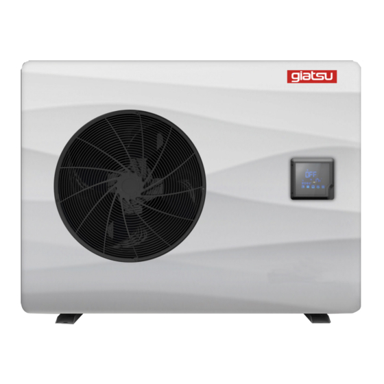
GIA-SWP-O-070LIO | GIA-SWP-O-110LIO
GIA-SWP-O-160LIO | GIA-SWP-O-190LIO
Por favor lea atentamente este manual antes de usar este producto.
Please, read carefully this manual before using the product.
Avant d'utiliser l'équipement, lisez attentivement les instructions.
Por favor leia atentamente este manual antes de usar o equipamento.
Per favore leggere attentamente questo manuale prima di utilizzare questo prodotto.
G r a c i a s | T h a n k y o u | M e r c i | O b r i g a d o | G r a z i e
LION
Advertisement
Table of Contents

Related Manuals for Giatsu LION

Summary of Contents for Giatsu LION
- Page 1 OWNER’S AND INSTALLATION MANUAL SWIMMING POOL HEAT PUMP LION GIA-SWP-O-070LIO | GIA-SWP-O-110LIO GIA-SWP-O-160LIO | GIA-SWP-O-190LIO Por favor lea atentamente este manual antes de usar este producto. Please, read carefully this manual before using the product. Avant d’utiliser l’équipement, lisez attentivement les instructions.
- Page 2 ENGLISH OWNER’S AND INSTALLATION MANUAL POOL HEAT PUMP LION GIA-SWP-O-070LIO | GIA-SWP-O-110LIO GIA-SWP-O-160LIO | GIA-SWP-O-190LIO...
-
Page 3: Table Of Contents
CONTENTS 1. Preface..................... 2. Specifications................Performance Data of Swimming Pool Heat Pump Unit......Performance diagram..............2.3 Dimensions for Swimming Pool Heat Pump Unit......3. Installation and connection............Illustration of installation.............. 11 Swimming Pool Heat Pumps Location.......... 3.3 Installation distance in your pool............. Swimming Pool Heat Pumps Plumbing.......... -
Page 4: Preface
1. PREFACE In order to provide our customers with quality, reliability and versatility, this product has been made to strict production standards. This manual includes all the necessary information about installation, debugging, discharging and maintenance. Please read this manual carefully before you open or maintain the unit. The manufacture of this product will not be held responsible if someone is injured or the unit is damaged, as a result of improper installation, debugging, or unnecessary maintenance. - Page 5 1. PREFACE This appliance can be used by children aged from 8 years and above and persons with reduced physical, sensory or mental capabilities or lack of experience and knowledge if the y have been give n supervision or instructio n concerning use o f the appliance in a safe way and understand the hazards involved.
- Page 6 1. PREFACE Caution & Warning 1. The unit can only be repaired by qualified installer centre personnel or an authorised dealer. for Europe market 2. This appliance is not intended for use by persons (including children) with reduced physical sensory or mental capabilities, or lack of experience and knowledge, unless they have been given supervision or instruction concerning use of the appliance by a person responsible for their safety.
-
Page 7: Specifications
2.SPECIFICATION 2.1 Performance data of Swimming Pool Heat Pump Unit *** REFRIGERANT : R32 GIA-SWP-O-110LIO GIA-SWP-O-070LIO UNIT Rated Heating Capacity(90Hz) 7.24 11.66 Btu/h 24700 39644 *Range 1.82~7.24 1.97~11.66 Btu/h 6210~24700 6698~39644 Rated Heating Power Input (90Hz) 1.28 2.00 *Range 0.15~1.28 0.16~2.00 Rated Running Current Input... - Page 8 2.SPECIFICATION 2.1 Performance data of Swimming Pool Heat Pump Unit *** REFRIGERANT : R32 GIA-SWP-O-160LIO GIA-SWP-O-190LIO UNIT Rated Heating Capacity(90Hz) 16.00 18.70 Btu/h 54400 63580 *Range 3.25~16.00 3.50~18.70 Btu/h 11050~5440 11900~63580 Rated Heating Power Input (90Hz) 2.91 3.65 *Range 0.30~2.91 0.32~3.65 Rated Running Current Input...
-
Page 9: Performance Diagram
2.SPECIFICATION 2.2 Performance diagram Model:GIA-SWP-0-070LIO Κ... - Page 10 2.SPECIFICATION 2.2 Performance diagram Model:GIA-SWP-0-110LIO...
- Page 11 2.SPECIFICATION 2.2 Performance diagram Model:GIA-SWP-0-160LIO Κ...
- Page 12 2.SPECIFICATION 2.2 Performance diagram Model:GIA-SWP-0-190LIO...
-
Page 13: Dimensions For Swimming Pool Heat Pump Unit
2.SPECIFICATION Dimensions for Swimming Pool Heat Pump Unit unit mm Model: GIA-SWP-O-070LIO / GIA-SWP-O-110LIO 1035 1002 Water outlet Water inlet unit mm Model: GIA-SWP-O-160LIO / GIA-SWP-O-190LIO 1165 1115 Water outlet Water inlet... -
Page 14: Installation And Connection
3.INSTALLATION AND CONNECTION 3.1 Installation illustration Valve Chlorinator cell Water outlet Water supply Pool Water inlet Sand filter Water pump (or other type filter) Installation items: The factory only provides the main unit and the water unit; the other items in the illustration are necessary spare parts for the water system ,that provided by users or the installer. -
Page 15: Swimming Pool Heat Pumps Location
3.INSTALLATION AND CONNECTION 3.2 Swimming Pool Heat Pumps Location The unit will perform well in any outdoor location provided that the following three factors are presented: 1. Fresh Air - 2. Electricity - 3. Pool filter piping The unit may be installed virtually anywhere outdoors. For indoor pools please consult the supplier. -
Page 16: Swimming Pool Heat Pumps Plumbing
3.INSTALLATION AND CONNECTION 3.4 Swimming Pool Heat Pumps Plumbing The Swimming Pool Heat Pumps exclusive rated flow titanium heat exchanger requires no special plumbing arrangements except bypass(please set the flow rate according to the nameplate). The water pressure drop is less than 10kPa at max. Flow rate. Since there is no residual heat or flame Temperatures, The unit does not need copper heat sink piping. -
Page 17: Swimming Pool Heat Pumps Electrical Wiring
3.INSTALLATION AND CONNECTION 3.5 Swimming Pool Heat Pumps Electrical Wiring NOTE: Although the unit heat exchanger is electrically isolated from the rest of the unit, it simply prevents the flow of electricity to or from the pool water. Grounding the unit is still required to protect you against short circuits inside the unit. -
Page 18: Use And Operation Instruction
4.Use and Operation Instruction 4.1.Interface display 4.2.Key and icon function instruction 4.2.1 Key function instruction Key symbols Function Designation Under the heating mode or heating mode under the automatic mode, the mute key operation is effective and Mute key used to enter and exit the mute mode with one click. It is used to switch the unit mode, temperature setting, Mode key and parameter setting. - Page 19 4.Use and Operation Instruction 4.2.2.Icon function instruction Function Icon symbol Designation It will display during cooling (there is no limit to startup & Cooling shutdown, and it is optional when the unit is cooling-only symbol unit or heating-and-cooling unit). It will display during heating (there is no limit to startup & Heating shutdown, and it is optional when the unit is heating-only symbol...
-
Page 20: Startup And Shutdown
4.Use and Operation Instruction 4.3. Startup & shutdown Keep long press of " "for 0.5 s to enter ON/OFF interface When there is no operation within 1 minute, it will display with half screen off When there is no operation within 15 minutes, it will display with full screen off Notes:... -
Page 21: Temperature Setting
4.Use and Operation Instruction Short press" " for to switch the mode circularly, after no operation for 2s, the current mode will be saved. Cooling mode Heating mode Automatic mode Operation descriptions: 1). Mode switch operation can only be conducted in the main interface. 2). -
Page 22: Clock Setting
4.Use and Operation Instruction Notes: Under the temperature setting interface, if short press " " , the system will return to the main interface without any changes saved; If there is no operation for 5 s, the system will automatically memorize user's setting, and return to the main interface. 4.6. - Page 23 4.Use and Operation Instruction 4.6.2 Setting and cancellation of timing ON and OFF Keep long press Short press " " of " " for 2s for and " " at the entering timing sametime setting Short press" " or Short press " "...
-
Page 24: Mute Setting
4.Use and Operation Instruction 4.7. Mute setting 4.7.1 One-click mute short press " " Flashing Notes: 1). If one-click mute and timing mute are stared at the same time, short press " " for canceling one-click mute and quitting the timing mute for this time. 2). -
Page 25: Keyboard Lock
4.Use and Operation Instruction Notes: 1). When the mute icon" " is lighten:The timing mute has been set, but it's not under mute status. 2). When the mute icon" " flash:It's under the mute status. 3). When the mute icon" "disappear: The timing mute is not set. -
Page 26: Parameter List And Breakdown Table
4.Use and Operation Instruction 4.10 . Parameter list and breakdown table 4.10.1 Electronic control fault table Can be judged according to the remote controller failure code and troubleshooting Fault Protect/fault Reason Elimination methods display Standby Normal boot Inlet Temp. Sensor Fault The temp. - Page 27 4.Use and Operation Instruction . Motor is in locked-rotor state C ange a new fan motor 2.The wire connection between Fan Motor2 Fault F032 2.Check the wire connection and make sure DC-fan motor module and fan they are in good contact motor is in bad contact Communication Fault Speed control module and main...
- Page 28 4.Use and Operation Instruction 4.10.2 Parameter list Meaning Default Remarks Adjustable Refrigeration target temperature set point 27ºC Heating the target temperature set point Adjustable 27ºC Automatic target temperature set point Adjustable 27ºC...
-
Page 29: Maintenance And Inspection
5. Maintenance and inspection Check the water supply device a nd the release often. You should avoid the condition of no water or air entering into system, as this will influence unit's performance and reliability. You should clear the pool/spa filter regularly to avoid damage to the unit as a result of the dirty of clogged filter. -
Page 30: Appendix
6. Appendix Interface drawing Controller interface diagram and definition OUT1 AC-L AC-N OUT3 OUT2 OUT5 OUT4 PC10 1002 485_B1 485_A1 485_B2 485_A2 Main board of the input and output interface instructions below Number Sign Meaning OUT1 Compressor (output 220-230 VAC) Water pump (output 220-230 VAC) OUT2 4-way valve (output 220-230 VAC) - Page 31 6. Appendix Number Sign Meaning +5V (output) +12V (output) Frequency conversion board communications LED controller communication Electronic expansion valve The port for centralized control Notes: When the unit uses EC fan, PWM-IN port is used for feedback input of EC fan by default, and AI/DI11 port is used as master-slave switch by default;...
- Page 32 6.Appendix Caution & Warning 1. The unit can only be repaired by qualified installer centre personnel or an authorised dealer(for Europe market). 2. This appliance can used by children aged from 8 years and above and persons with reduced physical, sensory or mental capabilities or lack of experience and knowledge if they have been given supervision or instruction concerning use of the appliance in a safe way and understand the hazards involved(for Europe market).
-
Page 33: Cable Especification
6.Appendix 6.2 Cable specification Single phase unit Nameplate Creepage protector Signal line maximum Phase line Earth line current No more 2 1.5mm 1.5mm 30mA less than 0.1 sec than 10A 2 2.5mm 2.5mm 30mA less than 0.1 sec 10~16A 2 4mm 30mA less than 0.1 sec 16 ~25A 2 6mm... - Page 34 Note...
- Page 35 Note...
- Page 36 C/ Industria, 13, Polígono Industrial El Pedregar. 08160 Montmeló. Barcelona (Spain) Tel (0034) 93 390 42 20 - Fax (0034) 93 390 42 05 info@giatsu.com - www.giatsu.com FRANCE PORTUGAL ITALY info.fr@giatsu.com info.pt@giatsu.com info.it@giatsu.com LITHUANIA info@giatsu. lt ADVERTENCIAS PARA LA ELIMINACIÓN CORRECTA DEL PRODUCTO SEGÚN ESTABLECE LA DIRECTIVA EUROPEA 2002/96/EC.
Need help?
Do you have a question about the LION and is the answer not in the manual?
Questions and answers