Table of Contents
Advertisement
Quick Links
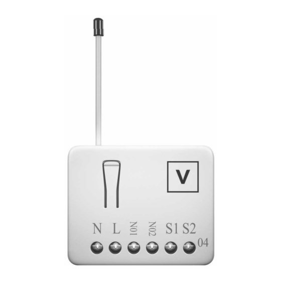
DS-100 double switch
Fig 1. Assembling
This in-wall dual relay switch module is a transceiver which is a Z-Wave Plus
enabled device and is fully compatible with any Z-Wave
TM
Z-Wave Plus
enabled devices displaying the Z-Wave Plus
used with it regardless of the manufacturer, and can also be used in other
TM
TM
enabled network.
TM
logo can also be
1
TM
manufacturer's Z-Wave
enabled networks. Mini size design let the module
can easily hide itself into the wall box and that will be good for the house
decoration.
There are many kind of application by using the module to switch AC power On
and Off, one main application is the light control. The new smart relay calibration
technology can reduce the inrush current caused by the load and let the module
work perfectly with many kind of light like incandescent, fluorescent and LED
light.
This in-wall switch module is able to detect Instant power wattage and overload
current (7.5A with resistive load) of connected light or appliances. When
detecting overload state, the Module will be disabled and its On/Off button will
be lockout of which LED will flash quickly. However, disconnect and re-connect
the Module will reset its overload condition to normal status.
TM
Adding to Z-Wave
Network
In the front casing, there is an on/off button with LED indicator below which is
used to toggle switch on and off or carry out inclusion, exclusion, reset or
association. When first power is applied, its LED flashes on and off alternately
and repeatedly at 0.5 second intervals. It implies that it has not been assigned a
node ID and start auto inclusion.
Auto Inclusion
The function of auto inclusion will be executed as long as the in wall switch does
not have Node ID and just connect the switch to main power.
Note: Auto inclusion timeout is 2 minute during which the node information of
explorer frame will be emitted once every several seconds. Unlike "inclusion"
function as shown in the table below, the execution of auto inclusion is free from
pressing the On/Off button on the Switch.
The table below lists an operation summary of basic Z-Wave functions. Please
refer to the instructions for your Z-Wave
TM
Certificated Primary Controller to
Advertisement
Table of Contents

Related Manuals for Vemmio DS-100

Summary of Contents for Vemmio DS-100
- Page 1 Z-Wave enabled networks. Mini size design let the module DS-100 double switch can easily hide itself into the wall box and that will be good for the house decoration. There are many kind of application by using the module to switch AC power On and Off, one main application is the light control.
-
Page 2: Led Indication
LED Indication controller manufacturer. Normal Whatever we switch On and off of the DS-100 by S1 S2 or On/Off Pressing INCLUDE_BUTTON three button or RF command, the LED will lights up 1 second and then times within 2 seconds will enter off. -
Page 3: Installation
DS-100 connector L, N. Value =0(0x00)] 2. Connect the wall switch to the DS-100 as Fig1 . Report ON:[Command Class Switch Binary, Switch Binary Report, Value 3. To manually turn ON the Switch, press and release the On/Off button. The... - Page 4 2-1-3 overload alarm report command supports 3 association groups which every group has one node support. Group1~Group3 support SWITCH_BINARY_REPORT, When DS-100 detect the overload, it will send Alarm Report to the correspond METER_REPORT_COMMAND_V3 Group。 For group 1, the Switch will report (1) ON/OFF status of Relay1 and Relay2 (2)
- Page 5 Meter Value 1 = 0x00 (W) to the node asked. Meter Value 2 = 0x00 (W) Meter Value 3 = 0x03 (W) Meter Get Command: [Command Class Meter, Meter Get, Scale =0x04(V)] Meter Value 4 = 0xEA (W) Meter(W) = Meter Value 3 *256 + Meter Value 4 = 100.2W Meter Report Command: 2-2-2 Accumulated Power Consumption (KW/h) [Command Class Meter,Meter Report,Rate Type = 0x01,Meter Type =...
- Page 6 Source End Point = 0x03 Since the endpoint is 3 so DS-100 will DS-100 will reply state of Relay1. If endpoint set to 2, DS-100 will reply state of reply ON(0xFF) when either Relay 1 or Relay2. If endpoint set to 3, DS-100 will reply ON (0xFF) when either Relay 1 Relay2 is ON, report OFF (0x00) when or Relay2 is ON, report OFF (0x00) when both Relay 1 and Relay2 are OFF.
- Page 7 2-3-3 METER_SUPPORTED_GET: : : : By using BINARY_SWITCH_SET Command of Multi Channel Command Class This command is to ask the endpoint of DS-100 what kind of meter data can Encapsulation Command, you can switch Relay1 ON/OFF by setting endpoint to...
- Page 8 ( Meter_Reset = 0x05) COMMAND_CLASS_MULTI_CHANNEL 2-3-5 METER_GET: : : : MULTI_CHANNEL_CMD_ENCAP Using meter get command to get the KWH, W, V, I, PF from endpoint of DS-100 Source End Point = 0x03 2-3-5-1 Get KWH from endpoint (Bit Address+Destination End Point = 0x01)
- Page 9 Parameter 1 = 0x10 (Scale = W = 0x02) Meter Type=0x01) (Precision = 2,Scale Bit1Bit0 = 0,Size Parameter 2 = 0x44 DS-100 Instant Power Consumption (W) Report example: = 4) Parameter 3 = 0x00 Accumulated Power Consumption = COMMAND_CLASS_MULTI_CHANNEL 0x000005FD = 15.33 KWh...
- Page 10 Parameter 1 = 0x20 (Scale = V = 0x04) Source End Point = 0x05 (this is the endpoint of command inquirer, here we assume endpoint is 5,if the inquirer doesn’t support multi Channel this DS-100 AC load Voltage report example:...
- Page 11 (Scale = A = 0x05) Source End Point = 0x05 (this is the endpoint of command inquirer, here we assume endpoint is 5,if the DS-100 AC load current (I) example: inquirer doesn’t support multi Channel this COMMAND_CLASS_MULTI_CHANNEL value will be 0) (Bit Address =0;Destination End Point...
- Page 12 6*10min= 1 hour Meter 0x7FFF 3-2 KWH Meter Report Period: Report If the setting is configured for 1hour (set value =6), the DS-100 will report its Period Accumulated Power Consumption (KW/h) every 1 hour to the node of Selected 1:Relay1 correspond Group.
- Page 13 3-3-3 Selected Relay1 and Relay2: : : : Default select is 3 state of relay1 and relay2. if the DS-100 relay change the state because of Both relay1 and relay2 can be controlled and report.
-
Page 14: Troubleshooting
“No RF Control” state. Whenever the AC power return from lost, DS-100 will restore the switch state After being set to “Protection by sequence” state, any intentional pressing of which could be SWITCH OFF 、 LAST SWITCH STATE 、 SWITCH ON. The default On/Off button or S2/S2 should be hold longer than 1 second, or the switch state setting is LAST SWITCH STATE. -
Page 15: Specification
DS-100-2: 908.40MHz; 916.00MHz(USA/Canada) / This equipment generates, uses and can radiate radio frequency energy and, if not DS-100-3: 922.5MHz/ 923.9MHz/ 926.3MHz (Taiwan/JP) installed and used in accordance with the instructions, may cause harmful interference to ** Specifications are subject to change and improvement without notice. - Page 16 • Consult the dealer or an experienced radio/TV technician for help. This device complies with Part 15 of the FCC Rules. Operation is subject to the following two conditions: (1) This device may not cause harmful interference, and (2) This device must accept any interference received, including interference that may cause undesired operation.
Need help?
Do you have a question about the DS-100 and is the answer not in the manual?
Questions and answers