
Subscribe to Our Youtube Channel
Related Manuals for NI NI PXIe-8840

Summary of Contents for NI NI PXIe-8840
- Page 1 PXI Express NI PXIe-8840 User Manual NI PXIe-8840 User Manual October 2013 374236A-01...
- Page 2 Support Worldwide Technical Support and Product Information ni.com Worldwide Offices Visit to access the branch office Web sites, which provide up-to-date ni.com/niglobal contact information, support phone numbers, email addresses, and current events. National Instruments Corporate Headquarters 11500 North Mopac Expressway Austin, Texas 78759-3504 USA Tel: 512 683 0100...
- Page 3 Warranty NI devices are warranted against defects in materials and workmanship for a period of one year from the invoice date, as evidenced by receipts or other documentation. National Instruments will, at its option, repair or replace equipment that proves to be defective during the warranty period.
- Page 4 For patents covering National Instruments products/technology, refer to the appropriate location: Help»Patents in your software, the file on your media, or the National Instruments Patent Notice at patents.txt ni.com/patents Export Compliance Information Refer to the Export Compliance Information at for the National Instruments global ni.com/legal/export-compliance...
- Page 5 Electromagnetic Compatibility Guidelines This product was tested and complies with the regulatory requirements and limits for electromagnetic compatibility (EMC) stated in the product specifications. These requirements and limits provide reasonable protection against harmful interference when the product is operated in the intended operational electromagnetic environment.
-
Page 6: Table Of Contents
NI PXIe-8840 Functional Description................1-3 National Instruments Software ..................1-4 Chapter 2 Installation and Configuration Installing the NI PXIe-8840 ..................... 2-1 How to Remove the Controller from the PXI Express Chassis........ 2-3 BIOS Setup Utility......................2-4 Accessing BIOS Setup Utility .................. 2-4 Main Setup Menu ..................... - Page 7 Front Panel Features ......................3-15 Data Storage........................3-15 Chapter 4 Common Configuration Questions General Questions......................4-1 Boot Options ........................4-1 Cables and Connections....................4-2 Software Driver Installation....................4-3 Upgrade Information......................4-4 PXI Express Configuration ....................4-5 Chapter 5 Troubleshooting viii | ni.com...
- Page 8 NI PXIe-8840 User Manual Appendix A Specifications Appendix B Technical Support and Professional Services © National Instruments | ix...
-
Page 9: About This Manual
This manual contains detailed instructions for installing and configuring the National Instruments PXIe-8840 embedded computer kit. How to Use the Documentation Set Begin by reading the NI PXIe-8840 Installation Guide, a brief quick-start guide that describes how to install and get started with your controller. This manual, the... -
Page 10: Introduction
Introduction Benefits of PXI Express The PXI (PCI eXtensions for Instrumentation) industry standard, an open specification governed by the PXI Systems Alliance (PXISA), has quickly gained adoption and grown in prevalence in test, measurement, and control systems since its release in 1998. One of the key elements driving the rapid adoption of PXI is its use of PCI in the communication backplane. -
Page 11: Ni Pxie-8840
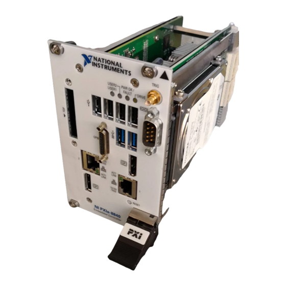
The NI PXIe-8840 PXI Express/CompactPCI Express embedded controller is a high-performance PXI Express/CompactPCI Express-compatible system controller. The NI PXIe-8840 controller integrates standard I/O features in a single unit by using state-of-the-art packaging. Combining an NI PXIe-8840 embedded controller with a PXI Express-compatible chassis, such as the NI PXIe-1082, results in a fully PC-compatible computer in a compact, rugged package. -
Page 12: Ni Pxie-8840 Functional Description
NI PXIe-8840 User Manual NI PXIe-8840 Functional Description The NI PXIe-8840 is a modular PC in a PXI Express 3U-size form factor. Figure 1-1 is a functional block diagram of the NI PXIe-8840. Following the diagram is a description of each logic block shown. -
Page 13: National Instruments Software
The PXIe Connectors connect the NI PXIe-8840 to the PXI Express/CompactPCI Express backplane. National Instruments Software National Instruments has developed several software tools you can use with the NI PXIe-8840. National Instruments hardware and software work together to help you make the most of your ™... - Page 14 API for communicating and controlling USB, Serial, GPIB, PXI, VXI, and various other types of instruments. This API aids in the creation of portable applications and instrument drivers. For information on writing your own PXI instrument driver with NI-VISA, refer to the NI-VISA Help and the file in the NI-VISA directory.
-
Page 15: Installation And Configuration
This section contains general installation instructions for the NI PXIe-8840. Consult your PXI Express chassis user manual for specific instructions and warnings. Plug in your chassis before installing the NI PXIe-8840. The power cord grounds the chassis and protects it from electrical damage while you install the module. - Page 16 Raise the injector/ejector handle until the module firmly seats into the backplane receptacle connectors. The front panel of the NI PXIe-8840 should be even with the front panel of the chassis. Tighten the four bracket-retaining screws on the top and bottom of the front panel to secure the NI PXIe-8840 to the chassis.
-
Page 17: How To Remove The Controller From The Pxi Express Chassis
What if the NI PXIe-8840 does not boot? section of Chapter 5, Troubleshooting. Figure 2-2 shows an NI PXIe-8840 installed in the system controller slot of an NI PXIe-1082 chassis. Figure 2-2. NI PXIe-8840 Controller Installed in a PXI Express Chassis... -
Page 18: Bios Setup Utility
The BIOS setup program includes menus for configuring settings and enabling NI PXIe-8840 controller features. Most users do not need to use the BIOS setup program, as the NI PXIe-8840 controller ships with default settings that work well for most configurations. -
Page 19: Main Setup Menu
The most commonly accessed and modified BIOS settings are in the Main setup menu. The Main setup menu reports the following configuration information: • BIOS Version and Build Date—These values indicate the version of the NI PXIe-8840 controller BIOS and the date on which the BIOS was built. •... -
Page 20: Sata Configuration Submenu
Real Time system. To achieve maximum possible Turbo Boost frequencies, also enable the C-States setting. When the BIOS is configured to boot LabVIEW Real-time, Turbo Boost is disabled 2-6 | ni.com... -
Page 21: Video Configuration Submenu
NI PXIe-8840 User Manual automatically. To manually enable Turbo Boost performance when in LabVIEW Real-Time mode, refer to the LabVIEW RT Configuration Overrides Submenu. • C-States—This setting enables or disables CPU power management. The default value is Enabled. Enabling C-States allows the processor to put idle CPU cores to sleep, allowing active cores to run at higher than base frequencies when Turbo Boost is enabled. -
Page 22: Expresscard Configuration Submenu
USB Devices—This item lists the total number of devices detected in the system, categorized by device type. • Legacy USB Support—This setting specifies whether or not legacy USB support is enabled. Legacy USB support refers to the ability to use a USB. keyboard and mouse during 2-8 | ni.com... -
Page 23: Serial Port Configuration Submenu
NI PXIe-8840 User Manual system boot or in a legacy operating system such as DOS. The default value is Enabled. This option is automatically disabled when booting LabVIEW Real-Time in order to reduce application jitter. • Overcurrent Reporting—This setting allows the BIOS to notify the operating system of any USB ports which source too much current. -
Page 24: Current Hardware Switch Settings
PXI Drive Boot—This setting specifies whether or not boot support is enabled for legacy mass storage devices, such as SCSI drives. When enabled, legacy mass storage controllers with boot support are displayed in the Boot Option Priorities menu. The default value is Enabled. 2-10 | ni.com... -
Page 25: Boot Settings Configuration Submenu
NI PXIe-8840 User Manual • PXE Network Boot—This setting specifies whether or not the PXE network boot agent is enabled. When enabled, the Intel Boot Agent is displayed in the Boot Option Priorities menu, allowing you to boot from a PXE server on the local subnet. Note that the Intel Boot Agent device names are preceded by IBA GE Slot in the Boot Option Priorities menu. -
Page 26: Hard Drive Bbs Priorities Submenu
The Save & Exit setup menu includes all available options for exiting, saving, and loading the BIOS default configuration. As an alternative to this screen, press <F9> to load optimal BIOS default settings and <F10> to save changes and exit setup. 2-12 | ni.com... -
Page 27: Bios Diagnostic Utilities
NI PXIe-8840 User Manual This setup menu includes the following settings: • Save Changes and Reset—Any changes made to BIOS settings are stored in NVRAM. The setup program then exits and reboots the controller. The <F10> key can also be used to select this option. -
Page 28: Memory Diagnostic Utility
Note instructed to turn off the controller and replace the memory. System CMOS The NI PXIe-8840 contains memory backed up by a battery to store BIOS configuration information. Complete the following steps to clear the CMOS contents: Power off the chassis. -
Page 29: Labview Rt Installation
IP settings, and install LabVIEW Real-Time software. Complete the following steps to install the LabVIEW RT software. Boot the NI PXI Express embedded controller into the real-time operating system. Refer to LabVIEW RT Configuration Switches... - Page 30 Click the Add/Remove Software button in the toolbar to launch the LabVIEW Real-Time Software Wizard. Install the LabVIEW Real-Time software and device drivers that you require on the RT target. Refer to the NI Web site at and enter the Info Code for the ni.com/info...
-
Page 31: Labview Rt Configuration Switches
If you are not using LabVIEW RT, these switches should remain in the OFF position. The controller reads these switches only after a system reset. The NI PXIe-8840 controller includes the following LabVIEW RT configuration switches: • Switch 1—Boot LabVIEW RT: Set this switch to ON to boot LabVIEW RT. -
Page 32: Drivers And Software
These files and directories are copied exactly from the manufacturer distribution disks, so the naming conventions vary from peripheral to peripheral. The directory contains the GPIB and PXI Platform NIDRIVERS Services drivers preinstalled on the controller. 2-18 | ni.com... -
Page 33: Pxi Express Features
PXI Express Features PXI Express Trigger Connectivity The SMB connector on the NI PXIe-8840 front panel can connect to or from any PXI Express backplane trigger line. A trigger allocation process is needed to prevent two resources from connecting to the same trigger line, resulting in the trigger being double-driven and possibly damaging the hardware. -
Page 34: Upgrading Ram
PXI Express specification at www.pxisa.org Upgrading RAM You can change the amount of installed RAM on the NI PXIe-8840 by upgrading the SO-DIMM. National Instruments offers the following SO-DIMMs for use with the NI PXIe-8840 controller. -
Page 35: Hard Drive Recovery
Note you want to keep. Installing an OS NI PXIe-8840 controllers may include a preinstalled OS. In some cases, you may want to install a different OS. When doing so, consider the following guidelines. Installing from a USB CD/DVD-ROM The NI PXIe-8840 supports the installation of Windows 7 from a USB CD/DVD-ROM. As an alternative to a USB CD/DVD-ROM drive, you can use an external SCSI CD/DVD-ROM with a PXI-SCSI adapter. -
Page 36: Removing An Expresscard
If you encounter too much resistance, do not force the card. Check the card orientation and try again. The NI PXIe-8840 automatically recognizes the ExpressCard and load the appropriate driver(s). Third-party cards may require that you install additional drivers. Contact your ExpressCard vendor for more information. -
Page 37: I/0 Information
I/0 Information Front Panel Connectors Table 3-1 lists various peripherals and their corresponding NI PXIe-8840 external connectors, bus interfaces, and functions. Table 3-1. NI PXIe-8840 Peripherals Overview Peripheral External Connector Description Video DisplayPort Intel ® HD Graphics controller Serial COM1 (9-pin DSUB) -
Page 38: Front Panel
Chapter 3 I/0 Information Front Panel Figure 3-1 shows the front panel layout and dimensions of the NI PXIe-8840. Dimensions are in inches (millimeters). Figure 3-1. NI PXIe-8840 Front Panel Layout and Dimensions 4.393 in. (111.58 mm) 3.750 in. (95.25 mm) 3.554 in. -
Page 39: Displayport
NI PXIe-8840 User Manual DisplayPort Figure 3-2 shows the location and pinouts for the DisplayPort connector on the NI PXIe-8840. Table 3-2 lists and describes the DisplayPort connector signals. Figure 3-2. DisplayPort Connector Location and Pinout NI PXIe-8840 Embedded Controller Table 3-2. -
Page 40: Com1
Hot Plug Detect Return DP_PWR COM1 Figure 3-3 shows the location and pinouts for the COM1 connector on the NI PXIe-8840. Table 3-3 lists and describes the COM1 connector signal. Figure 3-3. COM1 Connector Location and Pinout COM1 NI PXIe-8840 Embedded Controller 3-4 | ni.com... - Page 41 NI PXIe-8840 User Manual Table 3-3. COM1 Connector Signals Signal Name Signal Description DCD# Data Carrier Detect RXD# Receive Data TXD# Transmit Data DTR# Data Terminal Ready Ground DSR# Data Set Ready RTS# Ready to Send CTS# Clear to Send Ring Indicator Note: The pound symbol (#) indicates an active low signal.
-
Page 42: Ethernet
Chapter 3 I/0 Information Ethernet Figure 3-4 shows the location and pinouts for the Ethernet connector on the NI PXIe-8840. Table 3-4 lists and describes the Ethernet connector signals. Table 3-5 lists and describes the 10/100/1000 LAN connector LED states. - Page 43 NI PXIe-8840 User Manual Table 3-5. 10/100/1000 LAN Connector LED States Color LED State Condition LAN link is not established. On (steady state) LAN link is established. Green On (brighter and The controller is communicating with pulsing) another computer on the LAN.
-
Page 44: Universal Serial Bus
Figure 3-5 shows the location and pinouts for the Universal Serial Bus (USB) connectors on the NI PXIe-8840. Each controller has four USB 2.0 ports and two USB 3.0 ports on the front panel. Table 3-6 lists and describes the USB 2.0 connector signals. Table 3-7 lists and describes the USB 3.0 connector signals. - Page 45 NI PXIe-8840 User Manual Table 3-7. USB 3.0 Connector Signals (Continued) Signal Name Signal Description StdA_SSRX- USB Data Receive- StdA_SSRX+ USB Data Receive+ GND_DRAIN Ground StdA_SSTX- USB Data Transmit- StdA_SSTX+ USB Data Transmit+ © National Instruments | 3-9...
-
Page 46: Trigger
The TRIG connector is the software-controlled trigger connection for routing PXI triggers to or from the backplane trigger bus. Figure 3-6 shows the TRIG connector location on the NI PXIe-8840. Table 3-8 lists and describes the trigger connector signals. Refer to... -
Page 47: Gpib (Ieee 488.2)
NI PXIe-8840 User Manual GPIB (IEEE 488.2) Figure 3-7 shows the location and pinouts for the GPIB connector on the NI PXIe-8840. Table 3-9 lists and describes the GPIB connector signals. National Instruments provides a GPIB mating connector, part number 183285-0R2. - Page 48 SHIELD Chassis ground DIO5# Data Bit 5 DIO6# Data Bit 6 DIO7# Data Bit 7 DIO8# Data Bit 8 REN# Remote Enable 18 to 25 Logic Ground Note: The pound symbol (#) indicates an active low signal. 3-12 | ni.com...
-
Page 49: Expresscard/34 Slot
NI PXIe-8840 User Manual ExpressCard/34 Slot The NI PXIe-8840 controller is equipped with an ExpressCard/34 slot on the front panel, which provides I/O expansion and options for removable storage, Ethernet, and a variety of other I/O. Figure 3-8 shows the location and pinouts for the ExpressCard/34 slot on the NI PXIe-8840. - Page 50 REFCLK+ Reference Clock + Ground PERn0 PE Data Receive - PERp0 PE Data Receive + Ground PETn0 PE Data Transmit - PETp0 PE Data Transmit + Ground Note: The pound symbol (#) indicates an active low signal. 3-14 | ni.com...
-
Page 51: Front Panel Features
The USER2 LED is a bi-color green/yellow LED. You can define the USER2 LED to meet the needs of your LabVIEW application. Data Storage The NI PXIe-8840 has the following data storage features: • 2.5 in. SATA notebook internal hard drive •... -
Page 52: Common Configuration Questions
Chapter 3, Information. After shutting down my NI PXIe-8840 controller, the Ethernet LEDs continue to blink. Is it safe to remove my controller or disconnect power? The NI PXIe-8840 controller Ethernet device remains powered even after shutdown to support the Wake On LAN feature. -
Page 53: Cables And Connections
How do I plug both a PS/2 mouse and PS/2 keyboard into the controller? The NI PXIe-8840 has no PS/2 connector, and you need to use a USB Y-splitter cable as shown in Figure 4-1, or a similar device, to connect both a PS/2 mouse and PS/2 keyboard. National Instruments part number 778713-01 is such a cable and is available through the online catalog ni.com/products... -
Page 54: Software Driver Installation
How do I install or reinstall the GPIB driver? The NI-488.2 driver for your GPIB port is installed by default when your controller is first shipped from the factory. To change the default installed driver, complete the following steps: Download the latest GPIB driver from ni.com/downloads... -
Page 55: Upgrade Information
Common Configuration Questions Upgrade Information How do I upgrade system memory? You can change the amount of installed RAM on the NI PXIe-8840 by upgrading the DDR3L SO-DIMM. To upgrade the RAM, remove the NI PXIe-8840 from the PXI chassis. -
Page 56: Pxi Express Configuration
NI PXIe-8840 User Manual Where do I get the latest software drivers? The latest National Instruments software is available from ni.com/downloads PXI Express Configuration How do I use the SMB trigger on the front panel? For details, refer to the... -
Page 57: Troubleshooting
This chapter answers common troubleshooting questions you may have when using the NI PXIe-8840 embedded computer. What if the NI PXIe-8840 does not boot? Several problems can cause a controller not to boot. Here are some things to look for and possible solutions. - Page 58 Power off the chassis. Remove the controller from the chassis. Press and hold down the push button switch SW1 for 2 to 3 seconds. The SW1 switch location is shown in Figure 5-1. Reinstall the controller in the chassis. 5-2 | ni.com...
- Page 59 NI PXIe-8840 User Manual Figure 5-1. Clearing the CMOS Contents Push-Button Switch S1 © National Instruments | 5-3...
- Page 60 Specifications This appendix lists the electrical, mechanical, and environmental specifications of the NI PXIe-8840 embedded controller. Features NI PXIe-8840 ® ™ Intel Core i5 4400E (2.70 GHz dual core processor) On-die L2 cache 3 MB Single-Channel 1600 MHz 4 GB Standard...
- Page 61 (at 25 °C ambient temperature) Pollution Degree ..........2 Indoor use only. Clean the NI PXIe-8840 with a soft nonmetallic brush. Make sure that the Caution device is completely dry and free from contaminants before returning it to service. Operating Environment Ambient temperature range ......5 to 50 °C...
- Page 62 NI PXIe-8840 User Manual Relative humidity range........10% to 90%, noncondensing (Tested in accordance with IEC-60068-2-56.) The operating temperature must not be exceeded, even when used in a Caution chassis with a higher temperature range. Storage Environment Ambient temperature range ......-40 to 65 °C (Tested in accordance with IEC-60068-2-1 and IEC-60068-2-2.
- Page 63 Certification column. Environmental Management NI is committed to designing and manufacturing products in an environmentally responsible manner. NI recognizes that eliminating certain hazardous substances from our products is beneficial to the environment and to NI customers.
- Page 64 . This page contains the environmental regulations and ni.com/environment directives with which NI complies, as well as other environmental information not included in this document. Waste Electrical and Electronic Equipment (WEEE) At the end of the product life cycle, all products must be sent to EU Customers a WEEE recycling center.
- Page 65 Engineers make sure every question submitted online receives an answer. – Standard Service Program Membership—This program entitles members to direct access to NI Applications Engineers via phone and email for one-to-one technical support, as well as exclusive access to self-paced online training modules at ni.com/ .
Need help?
Do you have a question about the NI PXIe-8840 and is the answer not in the manual?
Questions and answers