
Related Manuals for NI PXIe-8135

Summary of Contents for NI PXIe-8135
- Page 1 PXI Express NI PXIe-8135 User Manual NI PXIe-8135 User Manual August 2013 373716B-01...
- Page 2 Worldwide Technical Support and Product Information ni.com Worldwide Offices Visit ni.com/niglobal to access the branch office Web sites, which provide up-to-date contact information, support phone numbers, email addresses, and current events. National Instruments Corporate Headquarters 11500 North Mopac Expressway Austin, Texas 78759-3504 USA Tel: 512 683 0100...
-
Page 3: Important Information
Warranty NI devices are warranted against defects in materials and workmanship for a period of one year from the invoice date, as evidenced by receipts or other documentation. National Instruments will, at its option, repair or replace equipment that proves to be defective during the warranty period. - Page 4 For patents covering National Instruments products/technology, refer to the appropriate location: Help»Patents in your software, the file on your media, or the National Instruments Patent Notice at patents.txt ni.com/patents Export Compliance Information Refer to the Export Compliance Information at for the National Instruments global ni.com/legal/export-compliance...
- Page 5 The Declaration of Conformity (DoC) contains important EMC compliance information and instructions for the user or installer. To obtain the DoC for this product, visit , search by ni.com/certification model number or product line, and click the appropriate link in the Certification column.
-
Page 6: Table Of Contents
National Instruments Software ..................1-4 Cleaning..........................1-5 Chapter 2 Installation and Configuration Installing the NI PXIe-8135 ..................... 2-1 How to Remove the Controller from the PXI Express Chassis........ 2-3 BIOS Setup Utility......................2-4 Accessing BIOS Setup Utility .................. 2-4 Main Setup Menu ..................... 2-5 Advanced Setup Menu.................... - Page 7 Ethernet ........................3-6 Parallel Port....................... 3-8 Universal Serial Bus ....................3-9 Trigger ........................3-11 GPIB (IEEE 488.2) ....................3-12 ExpressCard/34 Slot (Optional)................3-13 Removable Hard Drive (Optional) ................3-15 Front Panel Features ......................3-17 Data Storage........................3-17 viii | ni.com...
-
Page 8: Chapter 5 Troubleshooting
NI PXIe-8135 User Manual Chapter 4 Common Configuration Questions General Questions......................4-1 Boot Options........................4-1 Cables and Connections....................4-2 Software Driver Installation ..................... 4-3 Upgrade Information ......................4-4 PXI Express Configuration....................4-6 Chapter 5 Troubleshooting Appendix A Specifications Appendix B... -
Page 9: About This Manual
This manual contains detailed instructions for installing and configuring the National Instruments PXIe-8135 embedded computer kit. How to Use the Documentation Set Begin by reading the NI PXIe-8135 Installation Guide, a brief quick-start guide that describes how to install and get started with your controller. This manual, the... -
Page 10: Introduction
Introduction This chapter provides overview information for PXI Express and the NI PXIe-8135 embedded controller. Benefits of PXI Express The PXI (PCI eXtensions for Instrumentation) industry standard, an open specification governed by the PXI Systems Alliance (PXISA), has quickly gained adoption and grown in prevalence in test, measurement, and control systems since its release in 1998. -
Page 11: Ni Pxie-8135
1600 MHz memory controller, all the standard I/O, and an integrated hard drive. The removable hard drive variant has single channel DDR3. Note The NI PXIe-8135 also has an optional ExpressCard/34 expansion slot variant, and an optional front panel-accessible, removable hard drive. Functional Overview This section contains functional descriptions of each major logic block on the NI PXIe-8135 embedded computer. -
Page 12: Ni Pxie-8135 Functional Description
NI PXIe-8135 User Manual NI PXIe-8135 Functional Description The NI PXIe-8135 is a modular PC in a PXI Express 3U-size form factor. Figure 1-1 is a functional block diagram of the NI PXIe-8135. Following the diagram is a description of each logic block shown. -
Page 13: National Instruments Software
The PXI Express Connector connects the NI PXIe-8135 to the PXI Express/ CompactPCI Express backplane. • The Super I/O block represents the other peripherals supplied by the NI PXIe-8135. The NI PXIe-8135 has one serial port, and an ECP/EPP parallel port. •... -
Page 14: Cleaning
Linux has been improved by the NI-VISA driver for Linux and NI Modular Instruments are partially supported. For more information visit ni.com/linux Cleaning Use a dry, low-velocity stream of air to clean the NI PXIe-8135 controller. If needed, use a soft-bristle brush for cleaning around components. © National Instruments | 1-5... -
Page 15: Installation And Configuration
This section contains general installation instructions for the NI PXIe-8135. Consult your PXI Express chassis user manual for specific instructions and warnings. Plug in your chassis before installing the NI PXIe-8135. The power cord grounds the chassis and protects it from electrical damage while you install the module. - Page 16 Raise the injector/ejector handle until the module firmly seats into the backplane receptacle connectors. The front panel of the NI PXIe-8135 should be even with the front panel of the chassis. Tighten the four bracket-retaining screws on the top and bottom of the front panel to secure the NI PXIe-8135 to the chassis.
-
Page 17: How To Remove The Controller From The Pxi Express Chassis
NI PXIe-8135 does not boot? section of Chapter 5, Troubleshooting. Figure 2-2 shows an NI PXIe-8135 installed in the system controller slot of a National Instruments NI PXIe-1082 chassis. Figure 2-2. NI PXIe-8135 Controller Installed in a PXI Express Chassis... -
Page 18: Bios Setup Utility
The BIOS setup program includes menus for configuring settings and enabling NI PXIe-8135 controller features. Most users do not need to use the BIOS setup program, as the NI PXIe-8135 controller ships with default settings that work well for most configurations. -
Page 19: Main Setup Menu
• Processor Type, Base Processor Frequency, and Active Processor Cores—These values indicate the type of processor used in the NI PXIe-8135 controller, the speed of the processor, and the number of active processor cores. • Total Memory—This value indicates the size of system RAM detected by the BIOS. -
Page 20: Sata Configuration Submenu
The default value is Enabled. Enabling Hyper-Threading increases performance for some applications by adding virtual CPU cores. Hyper-Threading can increase application jitter, so care should be taken when enabling this setting on a Real Time system. When the BIOS 2-6 | ni.com... -
Page 21: Video Configuration Submenu
NI PXIe-8135 User Manual is configured to boot LabVIEW Real-Time, Hyper-Threading will be automatically disabled. In order to manually enable Hyper-Threading performance when in LabVIEW Real-Time mode, see the LabVIEW RT Configuration Overrides Submenu. • Enabled CPU Cores—This setting selects the number of active CPU cores for the processor. -
Page 22: Power/Wake Configuration Submenu
Reserved I/O—This setting determines the amount of I/O space, in bytes, that will be reserved by the BIOS for PCI-PCI bridges that may be hot-plugged in the ExpressCard slot. The default value for this setting is 4K bytes of I/O space. 2-8 | ni.com... -
Page 23: Pci Configuration Submenu
NI PXIe-8135 User Manual PCI Configuration Submenu Use this submenu to apply alternate settings to PCI devices. Normally, you do not need to modify these settings, as the factory default settings provide the most compatible and optimal configuration possible. •... -
Page 24: Usb Configuration Submenu
Serial Port Configuration—Use this setting to access the Serial Port Configuration submenu. Refer to the Serial Port Configuration Submenu section for more information. • Parallel Port Configuration—Use this setting to access the Parallel Port Configuration submenu. Refer to the Parallel Port Configuration Submenu section for more information. 2-10 | ni.com... -
Page 25: Serial Port Configuration Submenu
NI PXIe-8135 User Manual Serial Port Configuration Submenu • Serial Port—This setting enables or disables the onboard serial port. The default value is Enabled. • Device Settings—This item displays the current base address and interrupt request level (IRQ) information for the onboard serial port. -
Page 26: Current Hardware Switch Settings
To select a boot device, press <Enter> on the desired configuration option and select a boot device from the resulting menu. You can also disable certain boot devices by selecting Disabled. 2-12 | ni.com... -
Page 27: Boot Settings Configuration Submenu
NI PXIe-8135 User Manual Only one device of a given type will be shown in this list. If more than Note one device of the same type exists, use the Device BBS Priorities submenus to re-order the priority of devices of the same type. -
Page 28: Floppy Drive Bbs Priorities Submenu
The BIOS setup continues to be active. • Restore Factory Defaults—This option restores all BIOS settings to the factory default. This option is useful if the controller exhibits unpredictable behavior due to an incorrect or 2-14 | ni.com... -
Page 29: Bios Diagnostic Utilities
NI PXIe-8135 User Manual inappropriate BIOS setting. Notice that any nondefault settings such as boot order, passwords, and so on, are also restored to their factory defaults. The <F9> key can also be used to select this option. • Save As User Defaults—This option saves a copy of the current BIOS settings as the User Defaults. -
Page 30: System Cmos
Note instructed to turn off the controller and replace the memory. System CMOS The NI PXIe-8135 contains memory backed up by a battery to store BIOS configuration information. Complete the following steps to clear the CMOS contents: Power off the chassis. -
Page 31: Labview Rt Installation
IP settings, and install LabVIEW Real-Time software. Complete the following steps to install the LabVIEW RT software. Boot the NI PXI Express embedded controller into the real-time operating system. Refer to LabVIEW RT Configuration Switches... -
Page 32: Labview Rt Configuration Switches
If you are not using LabVIEW RT, these switches should remain in the OFF position. The controller reads these switches only after a system reset. The NI PXIe-8135 controller includes the following LabVIEW RT configuration switches: • Switch 1—Boot LabVIEW RT: Set this switch to ON to boot LabVIEW RT. -
Page 33: Drivers And Software
NI PXIe-8135 User Manual Figure 2-4 shows the location of the LabVIEW RT configuration switches. The switches are shown in the OFF position. Figure 2-4. LabVIEW RT Configuration Switches Switch 1—Boot LabVIEW RT Switch 3—Disable Startup VI Switch 2—Boot Safe Mode Switch 4—Reset IP Address... -
Page 34: Pxi Express Features
PXI Express Features PXI Express Trigger Connectivity The SMB connector on the NI PXIe-8135 front panel can connect to or from any PXI Express backplane trigger line. A trigger allocation process is needed to prevent two resources from connecting to the same trigger line, resulting in the trigger being double-driven and possibly damaging the hardware. -
Page 35: Upgrading Ram
If a single memory module is used, it must be installed in the lower socket. The NI PXIe-8135 removable hard drive variant has a single module slot that supports up to an 8 GB DDR3 SO-DIMM module. -
Page 36: Hard Drive Recovery
DDR3 SO-DIMM Sockets Hard Drive Recovery NI PXIe-8135 controllers include two methods of restoring the original factory condition of your hard drive. Hard drive-based recovery stores a factory backup on a separate portion of your hard drive allowing you to restore your controller without additional media. The NI PXIe-8135 controller also ships with an OS Recovery CD that allows you to reinstall your operating system onto your hard drive through an external USB CD/DVD-ROM. -
Page 37: Installing An Os
NI PXIe-8135 User Manual Installing an OS NI PXIe-8135 controllers include a preinstalled OS. In some cases, you may want to install a different OS. When doing so, consider the following guidelines. Installing from a USB CD/DVD-ROM The NI PXIe-8135 supports the installation of Windows 7 or Windows XP from a USB CD/DVD-ROM. -
Page 38: Removable Hard Drive
Tighten the thumb screws. If the thumb screws do not thread, the removable hard drive may not be fully inserted. Try removing and completely inserting the removable hard drive. Figure 2-6. Installing the Removable Hard Drive in an NI PXIe-8135 Controller Removable Hard Drive Thumb Screws (2x) 2-24 | ni.com... -
Page 39: Removing The Removable Hard Drive
NI PXIe-8135 User Manual Removing the Removable Hard Drive To remove the removable hard drive, complete the following steps: Power off the chassis. Loosen the thumb screws. Unseat the removable hard drive from the connector and remove it from the slot. -
Page 40: I/O Information
I/O Information Front Panel Connectors Table 3-1 lists various peripherals and their corresponding NI PXIe-8135 external connectors, bus interfaces, and functions. Table 3-1. NI PXIe-8135 Peripherals Overview Peripheral External Connector Description Video DisplayPort (2 connectors) ATI Radeon E4690 Embedded GPU... -
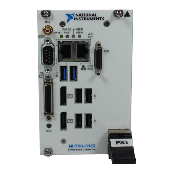
Page 41: Front Panel
Removable Hard Disk Drive Hard Drive Front Panel Figures 3-1 and 3-2 show the front panel layout and dimensions of the NI PXIe-8135. Dimensions are in inches [millimeters]. Figure 3-1. NI PXIe-8135 Front Panel Layout and Dimensions (ExpressCard Variant) 4.392 in. [111.56 mm] 3.658 in. - Page 42 NI PXIe-8135 User Manual Figure 3-2. NI PXIe-8135 Front Panel Layout and Dimensions (Removable Hard Drive Variant) 4.392 in. [111.56 mm] 3.658 in. [92.91 mm] 3.420 in. [86.86 mm] 3.553 in. [90.26 mm] 2.904 in. [73.77 mm] 2.738 in. [69.54 mm] 2.125 in.
-
Page 43: Displayport
Chapter 3 I/O Information DisplayPort Figure 3-3 shows the location and pinouts for the DisplayPort connectors on the NI PXIe-8135. Table 3-2 lists and describes the DisplayPort connector signals. Figure 3-3. DisplayPort Connector Location and Pinout NI PXIe-8135 Embedded Controller Table 3-2. -
Page 44: Com1
Return DP_PWR COM1 Figure 3-4 shows the location and pinouts for the COM1 connector on the NI PXIe-8135. Table 3-3 lists and describes the COM1 connector signal. AMP manufactures a serial port mating connector, part number 745491-5. Figure 3-4. COM1 Connector Location and Pinout... -
Page 45: Ethernet
Ethernet Figure 3-5 shows the location and pinouts for the dual stacked Ethernet connector on the NI PXIe-8135. Table 3-4 lists and describes the Ethernet connector signals. AMP manufactures a mating connector, part number 554739-1. Figure 3-5. Ethernet Connector Location and Pinout... - Page 46 NI PXIe-8135 User Manual Table 3-4. Ethernet Connector Signals Fast Ethernet Gigabit Ethernet TX_A+ TX_A- RX_B+ TX_C+ TX_C- RX_B- RX_D+ RX_D- The Ethernet controllers can perform an automatic crossover, thus Note eliminating the need for crossover cables. Table 3-5. 10/100/1000 LAN Connector LED States...
-
Page 47: Parallel Port
Parallel Port Figure 3-6 shows the location and pinouts for the IEEE 1284 (parallel) connector on the NI PXIe-8135. Table 3-6 lists and describes the IEEE 1284 connector signals. Parallel port adapter cables are available from National Instruments, part number 777169-01. -
Page 48: Universal Serial Bus
Universal Serial Bus Figure 3-7 shows the location and pinouts for the Universal Serial Bus (USB) connectors on the NI PXIe-8135. Each controller has 4 USB ports on the front panel. Table 3-7 lists and describes the USB connector signals. - Page 49 Table 3-8. USB 3.0 Connector Signals Signal Name Signal Description Cable Power (+5 V) -Data USB Data - +Data USB Data + Ground StdA_SSRX- USB Data Receive- StdA_SSRX+ USB Data Receive+ GND_DRAIN Ground StdA_SSTX- USB Data Transmit- StdA_SSTX+ USB Data Transmit+ 3-10 | ni.com...
-
Page 50: Trigger
The TRIG connector is the software-controlled trigger connection for routing PXI Express triggers to or from the backplane trigger bus. Figure 3-8 shows the TRIG connector location on the NI PXIe-8135. Table 3-9 lists and describes the trigger connector signals. -
Page 51: Gpib (Ieee 488.2)
Chapter 3 I/O Information GPIB (IEEE 488.2) Figure 3-9 shows the location and pinouts for the GPIB connector on the NI PXIe-8135. Table 3-10 lists and describes the GPIB connector signals. ITT Canon manufactures a GPIB mating connector, part number MDSM-25SC-Z11-V51. -
Page 52: Expresscard/34 Slot (Optional)
Note: The pound symbol (#) indicates an active low signal. ExpressCard/34 Slot (Optional) The NI PXIe-8135 controller can be equipped with an optional ExpressCard/34 slot on the front panel, providing I/O expansion and options for removable storage. Figure 3-10 shows the location and pinouts for the ExpressCard/34 slot on the NI PXIe-8135. - Page 53 PE Reset +3.3V Power +3.3V Power CLKREQ# Clock Request CPPE# PE Presence REFCLK- Reference Clock - REFCLK+ Reference Clock + Ground PERn0 PE Data Receive - PERp0 PE Data Receive + Ground PETn0 PE Data Transmit - 3-14 | ni.com...
-
Page 54: Removable Hard Drive (Optional)
Note: The pound symbol (#) indicates an active low signal. Removable Hard Drive (Optional) The NI PXIe-8135 controller can be equipped with an optional removable hard drive on the front panel, providing an option for removable storage. Figure 3-11 shows the location and pinouts for the removable hard drive on the NI PXIe-8135. - Page 55 Table 3-12. Removable Hard Drive Connector Signals (Continued) Signal Name Signal Description Ground 3.3 V Power 3.3 V Power 3.3 V Power Ground Ground Ground Power Power Power Ground GND/Optional Ground/Act/Staggerd Spinup Ground No Connect No Connect No Connect 3-16 | ni.com...
-
Page 56: Front Panel Features
The USER2 LED is a bi-color green/yellow LED. You can define the USER2 LED to meet the needs of your LabVIEW application. Data Storage The NI PXIe-8135 has the following data storage features: • Internal Serial ATA hard drive –... -
Page 57: Common Configuration Questions
Chapter 3, Information. After shutting down my NI PXIe-8135 controller, the Port 1 Ethernet LEDs continue to blink. Is it safe to remove my controller or disconnect power? The NI PXIe-8135’s port 1 Intel 82579 Ethernet device remains powered even after shutdown. -
Page 58: Cables And Connections
How do I plug both a PS/2 mouse and PS/2 keyboard into the controller? The NI PXIe-8135 has no PS/2 connector, and you need to use a USB Y-splitter cable as shown in Figure 4-1, or a similar device, to connect both a PS/2 mouse and PS/2 keyboard. National Instruments part number 778713-01 is such a cable and is available through the online catalog ni.com/products... -
Page 59: Software Driver Installation
How do I connect a standard 25-pin LPT cable to the NI PXIe-8135? The NI PXIe-8135 uses a type C LPT connector. Most parallel port devices use a type A connector. To use a device with a standard type A LPT connector, you need to use a type C-to-type A LPT adapter. -
Page 60: Upgrade Information
Upgrade Information How do I upgrade system memory? You can change the amount of installed RAM on the NI PXIe-8135 by upgrading the DDR3 SO-DIMMs. To upgrade the RAM, remove the NI PXIe-8135 from the PXI Express chassis. To optimize both memory capacity and system performance, use the same size and speed memory module in each of the two module slots. - Page 61 My PXI or VXI Controller?, at ni.com My NI PXIe-8135 does not have an internal floppy drive. Is there a way to use an external drive? Yes. The NI PXIe-8135 controller supports and can boot from USB floppy drives. Refer to the Boot Options section for more information.
-
Page 62: Pxi Express Configuration
Why doesn’t the NI PXIe-8135 work with the PXI-8220 or PXI-8221? The serialized IRQ line is not routed to the Intel 7 Series chipset on the NI PXIe-8135. This prevents PC cards using ISA interrupts from working with the NI PXIe-8135. -
Page 63: Troubleshooting
This chapter answers common troubleshooting questions you may have when using the NI PXIe-8135 embedded computer. What if the NI PXIe-8135 does not boot? Several problems can cause a controller not to boot. Here are some things to look for and possible solutions. - Page 64 As an alternative method, complete the following steps: Power off the chassis. Remove the controller from the chassis. Press the Clear CMOS button (SW2) as shown in Figure 5-1. Wait ten seconds. Reinstall the controller in the chassis. 5-2 | ni.com...
- Page 65 NI PXIe-8135 User Manual Figure 5-1. Clearing the CMOS Contents Push-Button Switch SW2 © National Instruments | 5-3...
-
Page 66: Appendix A Specifications
Specifications This appendix lists the electrical, mechanical, and environmental specifications of the NI PXIe-8135 embedded controller. Features NI PXIe-8135 Intel Core i7 3610 QE CPU Frequency 2.3 GHz (base), 3.3 GHz (single-core Turbo mode) On-die L2 cache 256 KB x4 (256 KB per core) - Page 67 (at 25 °C ambient temperature) Pollution Degree ..........2 Indoor use only. Clean the NI PXIe-8135 with a soft nonmetallic brush. Make sure that the Caution device is completely dry and free from contaminants before returning it to service. A-2 | ni.com...
-
Page 68: Operating Environment
NI PXIe-8135 User Manual Operating Environment NI PXIe-8135 Ambient temperature range Standard ..........5 to 50 °C (Tested in accordance with IEC-60068-2-1 and IEC-60068-2-2. Meets MIL-PRF-28800F Class 3 high temperature limit.) Extended Temperature Option ..........0 to 55 °C (Tested in accordance with IEC-60068-2-1 and IEC-60068-2-2. -
Page 69: Electromagnetic Compatibility
Online Note Product Certification section. Using the NI PXIe-8135 in a manner not described in this document may Caution impair the protection the NI PXIe-8135 provides. Electromagnetic Compatibility This product meets the requirements of the following EMC standards for electrical equipment for measurement, control, and laboratory use: •... -
Page 70: Battery Replacement And Disposal
. This page contains the environmental regulations and ni.com/environment directives with which NI complies, as well as other environmental information not included in this document. Waste Electrical and Electronic Equipment (WEEE) At the end of the product life cycle, all products must be sent to EU Customers a WEEE recycling center. - Page 71 Engineers make sure every question submitted online receives an answer. – Standard Service Program Membership—This program entitles members to direct access to NI Applications Engineers via phone and email for one-to-one technical support, as well as exclusive access to self-paced online training modules at ni.com/ .
- Page 72 Appendix B Technical Support and Professional Services You also can visit the Worldwide Offices section of to access the branch ni.com/niglobal office Web sites, which provide up-to-date contact information, support phone numbers, email addresses, and current events. B-2 | ni.com...
- Page 73 Glossary Symbol Prefix Value nano µ micro milli kilo mega giga tera Symbols ° Degrees. Ω Ohms. Percent. Amperes. Alternating Current. Bytes. backplane An assembly, typically a printed circuit board, with connectors and signal paths that bus the connector pins. BIOS Basic Input/Output System—BIOS functions are the fundamental level of any PC or compatible computer.
- Page 74 LCD computer displays and digital projectors. It was developed by an industry consortium, the Digital Display Working Group (DDWG). Extended Capabilities Parallel. EEPROM Electronically Erasable Programmable Read Only Memory. Electromagnetic Compatibility. Electromagnetic interference. G-2 | ni.com...
- Page 75 NI PXIe-8135 User Manual Enhanced Parallel Port. expansion ROM An onboard EEPROM that may contain device-specific initialization and system boot functionality. Federal Communications Commission. 1. Grams. 2. A measure of acceleration equal to 9.8 m/s GPIB General Purpose Interface Bus (IEEE 488).
- Page 76 PXI Express backplane. A transfer can be either a read or a write. Megabytes of memory. MTBF Mean time between failure. NI-488 or NI-488.2 The National Instruments software for GPIB systems. NI-DAQ The National Instruments software for data acquisition instruments.
- Page 77 NI PXIe-8135 User Manual Peripheral Component Interconnect—The PCI bus is a high-performance 32-bit or 64-bit bus with multiplexed address and data lines. PCMCIA Personal Computer Memory Card International Association. peripheral Any hardware device connected to a computer, such as a monitor, keyboard, printer, plotter, disk or tape drive, graphics tablet, scanner, mouse, and so on.
- Page 78 Glossary Universal Serial Bus. Volts. Video Graphics Array—The minimum video display standard for all PCs. Watts. G-6 | ni.com...
-
Page 79: General Questions
4-2 AMT Configuration Submenu, 2-9 Boot Settings Configuration menu, 2-13 Boot Setup menu, 2-12 BIOS checking settings, 4-1 calibration certificate (NI resources), B-1 Diagnostic Utilities, 2-15 CD/DVD ROM Drive BBS Priorities menu, flashing new BIOS, 4-5 2-13 setup... - Page 80 3-2, 3-3 installation features, 3-17 GPIB (IEEE 488.2), 4-3 LEDs, 4-1 video, 4-3 functional overview of NI PXIe-8135, 1-2 NI resources, B-1 obtaining latest drivers, 4-5 drivers (NI resources), B-1 GPIB (IEEE 488.2) connector location and pinout (figure), 3-12...
- Page 81 See also configuration COM1, 3-5 injector/ejector handle position Ethernet, 3-6 (caution), 2-2 GPIB (IEEE 488.2), 3-12 NI PXIe-8135 installed in a PXI Express parallel port, 3-8 chassis (figure), 2-3 Measurement Studio, 1-4 procedure, 2-1 Memory Configuration Submenu, 2-9 removing NI PXIe-8135 from PXI...
- Page 82 Serial/Parallel Port Configuration menu, 2-10 from USB CD/DVD-ROM, 2-23 Parallel Port menu, 2-11 overview, 2-23 Serial Port menu, 2-11 setting up the NI PXIe-8135 BIOS, 2-4 shock and vibration specifications, A-3 parallel port SO-DIMM logic block, 1-3 connector, 3-1 software...
- Page 83 4-2 system CMOS, 2-16 using with PS/2 mouse and keyboard, system reset pushbutton, 3-17 technical support, B-1 training and certification (NI resources), B-1 trigger, 4-6 connector location and pinout (figure), 3-11 connector signals (table), 3-11...
Need help?
Do you have a question about the PXIe-8135 and is the answer not in the manual?
Questions and answers