Advertisement
Quick Links
Advertisement

Related Manuals for Acces USB-II-16


Summary of Contents for Acces USB-II-16
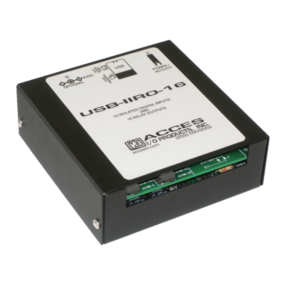
- Page 1 10623 Roselle Street, San Diego, CA 92121 (858) 550-9559 Fax (858) 550-7322 contactus@accesio.com www.accesio.com ISOLATED DIGITAL INPUT / RELAY OUTPUT BOARD MODELS USB-IIRO-16, USB-II-16, USB-RO-16, USB-IIRO-8 and USB-IIRO-4 USER MANUAL File: MUSB-IIRO-16.B1j...
- Page 2 Notice The information in this document is provided for reference only. ACCES does not assume any liability arising out of the application or use of the information or products described herein. This document may contain or reference information and products protected by copyrights or patents and does not convey any license under the patent rights of ACCES, nor the rights of others.
- Page 3 Terms and Conditions If a unit is suspected of failure, contact ACCES' Customer Service department. Be prepared to give the unit model number, serial number, and a description of the failure symptom(s). We may suggest some simple tests to confirm the failure.
-
Page 4: Table Of Contents
TABLE OF CONTENTS Chapter 1: Introduction............................. 5 Figure 1-1: Block Diagram........................... 7 Figure 1-2: Example of one Input Circuit..................... 7 Chapter 2: Installation............................8 Chapter 3: Option Selection ..........................9 Figure 3-1: Option Selection Map......................10 Chapter 4: USB Address Information ......................11 Table 4-1: Model Description to PID...................... -
Page 5: Chapter 1: Introduction
Chapter 1: Introduction This board is an ideal solution for adding portable, easy-to-install digital I/O to any computer with a USB port. As a USB 2.0 high speed device it offers the fastest speed available with the USB bus, while being compatible with both USB 1.1 and USB 2.0 ports. - Page 6 Functional Description FEATURES: • High-Speed USB 2.0 device, USB 1.1 compatible • 16 optically isolated inputs • 16 Form C electromechanical 1A relays • Internal, removable screw terminal board for easy wiring • Small (4" x 4"x 1.25") rugged industrial enclosure •...
- Page 7 The LED on the front of the enclosure is used to indicate power and data transmissions. When the LED is in an illuminated steady green state, this signifies that the board is successfully connected to the computer and has been detected and configured by the operating system. When the LED flashes continuously, this signifies that there is data being transmitted over the USB bus.
-
Page 8: Chapter 2: Installation
Chapter 2: Installation Software CD Installation These paragraphs are intended to detail the software installation steps as well as describe what is being installed. must be installed onto your The software provided with this board is contained on one CD and hard disk prior to use. -
Page 9: Chapter 3: Option Selection
Chapter 3: Option Selection Refer to the setup programs on the CD provided with the board. Also, refer to the Block Diagram and the Option Selection Map when reading this section of the manual. Input Power This is an option for applications that use more current than what your computer can provide on the USB port (typically 500 mA). - Page 10 0.20" 0.20" FILTER FILTER VUSB VEXT Pin 1 0.20" 0.20" 3.775” Figure 3-1: Option Selection Map Manual USB-IIRO-16 Family...
-
Page 11: Chapter 4: Usb Address Information
Chapter 4: USB Address Information Use the provided driver to access the USB board. This driver will allow you to determine how many supported USB devices are currently installed, and each device’s type. This information is returned as a Vendor ID (VID), Product ID (PID) and Device Index. The board’s VID is “0x1605". -
Page 12: Chapter 5: Programming
Chapter 5: Programming The driver software provided with the board uses a 32-bit .dll front end compatible with any Windows programming language. Samples provided in Borland C++Builder, Borland Delphi, Microsoft Visual Basic, and Microsoft Visual C++ demonstrate the use of the driver. The following functions are provided by the driver in Windows. -
Page 13: Chapter 6: Connector Pin Assignments
Chapter 6: Connector Pin Assignments Relay outputs are connected to the board via a 50-pin HEADER type connector named P3. The mating connector is an IDC type with 0.1 inch centers or equivalent. The wiring may be directly from the signal sources or may be on ribbon cable from screw terminal accessory boards such as the STA-50. - Page 14 Isolated Inputs are connected to the board via a 34-pin HEADER type connector named P2. The mating connector is an IDC type with 0.1 inch centers or equivalent. NAME FUNCTION IN00 A Isolated Input 00 A IN00 B Isolated Input 00 B IN01 A Isolated Input 01 A IN01 B...
-
Page 15: Chapter 7: Specifications
Chapter 7: Specifications ISOLATED INPUTS Number of inputs: Sixteen Type: Non-polarized, optically isolated from each other and from the computer (CMOS compatible) Voltage Range: 3 to 31 DC or AC Rms (40 to 10000 Hz) Isolation: 500V*(see note) channel-to-ground or channel-to channel Input Resistance: 1.8K ohms in series with opto coupler Filter Response Times:... - Page 16 ENVIRONMENTAL Operating Temp: 0 - 70 C (Non-icing) Weight: 14.5 oz *Notes on Isolation: Opto-Isolators and connectors are rated for at least 500V, but isolation voltage breakdowns will vary and is affected by factors like cabling, spacing of pins, spacing between traces on the PCB, humidity, dust and other environmental factors.
- Page 17 Customer Comments If you experience any problems with this manual or just want to give us some feedback, please email us at: manuals@accesio.com. Please detail any errors you find and include your mailing address so that we can send you any manual updates. 10623 Roselle Street, San Diego CA 92121 Tel.
Need help?
Do you have a question about the USB-II-16 and is the answer not in the manual?
Questions and answers