Advertisement
Table of Contents
- 1 1. Cautions
- 2 2. Fixed and Installation
- 3 Advanced Access Control
- 4 4. LED Indicators, Wires, Auxiliary Input and Output
- 5 5. RS485 Address Setting, Restore Factory Setting, Terminal Resistance Setting
- 6 6. Connection of Lock
- 7 TCP/IP Communication
- 8 7. Equipment Communication
- Download this manual
Advertisement
Table of Contents

Summary of Contents for eSSL C3-400
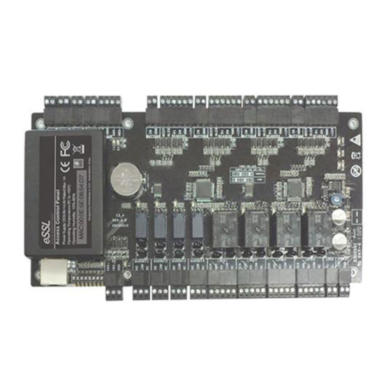
- Page 1 USER MANUAL C3-400 Installation Instructions and Connection Guide www.esslsecurity.com...
- Page 2 C 3- 400 I nstallation I nstructions and C onnection G uide 1. Cautions Please note the following cautions. Mis-operation may lead to personal injury or V alve r egulated l ead-acid batter y: equipment failure: Constant voltage charge voltage regulation 1)Do not energize the system before installation is complete;...
- Page 3 4. LED Indicators, Wires, Auxiliary Input And Output Notes: 1)Meaning of LED indicators: LINK indicator(green): always(green) indicates TCP/IP 2)Recommended use of wires: communication is proper; A Use 2-conducotor power cord ACT indicator(yellow): flashing indicates data is in transmitting B Use 6-conductor wire between wiegand reader and control panel through TCP/IP communication.
- Page 4 5. RS485 Address Setting, Restore Factory Setting, Terminal Resistance Setting Set RS485 address through DIP switch: 1) Place 1-6 on DIP switch are for setting the number of control panels when communicating through RS485, it is adopted for binary coding, and little endian, the address represented by place 1-6 are shown as figurue(5-1).
- Page 5 7. Equipment Communication The background PC software is able to communicate with the system according to two protocols(RS485 and TCP/IP) for data exchange and remote management. The communication cable should be as far away from high-voltage lines as possible. Do not keep the communication cable in parallel with power cords or bind them together.
- Page 6 #24, Shambavi Building, 23rd Main, Marenahalli, JP Nagar 2nd Phase, Bengaluru - 560078 Phone : 91-8026090500 | Email : sales@esslsecurity.com www.esslsecurity.com...

Need help?
Do you have a question about the C3-400 and is the answer not in the manual?
Questions and answers