Table of Contents
Advertisement
Available languages
Available languages
ATTACH YOUR RECEIPT HERE
Serial Number
Questions, problems, missing parts? Before returning to your retailer, call our customer
service department at 1-888-3KOBALT (1-888-356-2258), 8 a.m. - 8 p.m., EST,
Monday - Friday.
AB16358
Purchase Date
1
ITEM #0786032
MITER SAW
STAND
MODEL #KMS-S16
Français p. 18
Español p. 35
kobalttools.com
Advertisement
Chapters
Table of Contents

Subscribe to Our Youtube Channel
Related Manuals for Kobalt KMS-S16

Summary of Contents for Kobalt KMS-S16
- Page 1 ITEM #0786032 MITER SAW STAND MODEL #KMS-S16 Français p. 18 Español p. 35 ATTACH YOUR RECEIPT HERE Serial Number Purchase Date Questions, problems, missing parts? Before returning to your retailer, call our customer service department at 1-888-3KOBALT (1-888-356-2258), 8 a.m. - 8 p.m., EST, Monday - Friday.
-
Page 2: Table Of Contents
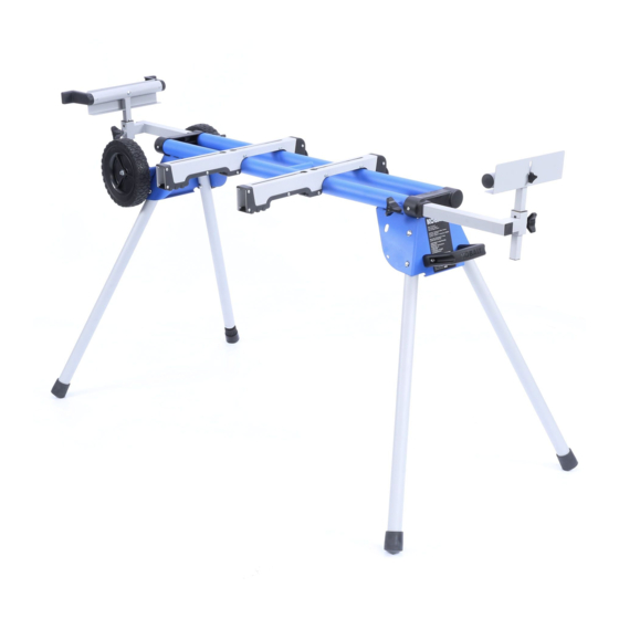
TABLE OF CONTENTS Product Specifications......................Package Contents ....................... Hardware Contents ......................Safety Information ....................... Preparation .......................... Assembly Instructions ......................Operating Instructions ......................Adjustment Instructions ...................... Care and Maintenance ....................... Three-Year Warranty ......................Replacement Parts List ...................... PRODUCT SPECIFICATIONS DESCRIPTION SPECIFICATIONS Stand height to mounting brackets 32-1/4 in. -
Page 3: Package Contents
PACKAGE CONTENTS PART DESCRIPTION QUANTITY Left Work Support Wheels Mounting Brackets Miter Saw Stand Right Work Support Handle 5mm Hex Key HARDWARE CONTENTS Hardware for handle Hardware for wheels Miter saw mounting hardware Spring Flat Washer 6 Washer 6 Wheel Sleeve Washer 14 Washer 10 Qty. -
Page 4: Safety Information
SAFETY INFORMATION IMPORTANT SAFETY INSTRUCTIONS WARNING CAREFULLY READ AND FOLLOW ALL WARNING AND INSTRUCTIONS ON YOUR PRODUCT AND IN THIS MANUAL. SAVE THIS MANUAL. MAKE SURE ALL USERS ARE FAMILIAR WITH ITS WARNINGS AND INSTRUCTIONS WHEN USING THE TOOL. Improper operation, maintenance or modification of tools or equipment could result in serious injury and/or property damage. - Page 5 SAFETY INFORMATION • DUST PROTECTION. Use of power tools can generate and/or disperse dust, which may cause serious and permanent respiratory damage. Direct particles away from face and body. Always operate machines in well-ventilated area and provide for proper dust removal. Use dust collection system wherever possible.
-
Page 6: Preparation
PREPARATION Before beginning assembly of product, make sure all parts are present. Compare parts with package contents list and hardware content list. If any part is missing or damaged, DO NOT attempt to assemble the product. Estimated Assembly Time: 4 minutes Tools Required for Assembly (not included): 13 mm or adjustable wrench. - Page 7 ASSEMBLY INSTRUCTIONS 2. Repeat with the remaining three legs. Lift the stand and place it in an upright position. Note: Check to ensure the stand is stable and all the legs have the locking pins (I) engaged. TO SECURE/LEVEL THE STAND With the stand open and resting on a flat and level surface, the stand should not move or rock from side to side.
- Page 8 ASSEMBLY INSTRUCTIONS STAND ASSEMBLY 1. Align the holes on the handle (F) with holes on the miter saw stand (D). Insert the hexagon bolts M6 x 30 mm (CC) through flat washers 6 (JJ) and into the mounting holes on the handle and miter saw stand. Tighten the hexagon bolts M6 x 30mm (CC) with 5mm hex key (G).
- Page 9 ASSEMBLY INSTRUCTIONS 3. Loosen the locking knob (K) but do not remove it. Place the rod on the left work support (A) into main unit as shown. Tighten the locking knob (K). Repeat for the right work support (E). Note: Hand tighten locking knob. ATTACHING SAW TO MOUNTING BRACKETS Make sure the saw is positioned for best balance and stability.
- Page 10 ASSEMBLY INSTRUCTIONS 2. Place a saw mounting bracket underneath the raised side of saw, aligning the mounting holes on the miter saw base with the nut inside the top of the bracket. Feed a hexagon bolt M6 x 55mm (BB) down through a spring washer 6 (II), a flat washer 6 (JJ), into the nut inside the top of the bracket and a mounting hole in the saw.
- Page 11 ASSEMBLY INSTRUCTIONS If the saw has holes that do not line up with the slots in the saw mounting brackets: 1. Unplug the saw and lock saw arm in the down position. Mount the saw to a mounting surface at least 1/2 in. thick using 5/16 in.
- Page 12 ASSEMBLY INSTRUCTIONS MOUNT THE MITER SAW TO THE STAND 1. Lift the saw and bracket assembly, allowing the assembly to tilt slightly toward your body. While still tilted toward you, hook the front edge of the bracket assembly onto the front rail of the stand. 2.
-
Page 13: Operating Instructions
OPERATING INSTRUCTIONS APPLICATIONS: You may use this tool for the following purpose: To provide a stable, secure work surface for a miter saw. USING THE EXTENSION RAILS Use the extension rails when working with larger work pieces. To extend the rails: •... - Page 14 OPERATING INSTRUCTIONS USING THE STOPS • Loosen the stop adjustment knob (P). • Move the stop (Q) to the maximum height position. • Tighten the stop adjustment knob (P). STORING THE STAND WARNING The miter saw must be removed from the stand and the extension rails should be retracted before converting the stand to its vertical storage position.
-
Page 15: Adjustment Instructions
OPERATING INSTRUCTIONS • Grasp the handle (R) to tilt the stand until it stands on the wheels (B) and stand support (S). ADJUSTMENT INSTRUCTIONS BRACKET ADJUSTMENT BOLT Mounting brackets are designed to fit snugly over the stand rails. With the locking levers in the lowered (locked) position, you should not be able to remove the saw and bracket assembly from the rails. -
Page 16: Care And Maintenance
CARE AND MAINTENANCE WARNING When servicing, use only identical replacement parts. Use of any other parts may create a hazard or cause product damage. Avoid using solvents when cleaning plastic parts. Most plastics are susceptible to damage from various types of commercial solvents and may be damaged by their use. Use clean cloths to remove dirt, dust, oil, grease, etc. -
Page 17: Replacement Parts List
Right work support 786032004 Handle 786032005 5mm Hex key 786032006 Miter saw mounting hardware 786032007 Hardware for handle 786032008 Hardware for wheels 786032009 Printed in China KOBALT® and the K Design® are registered trademarks of LF, LLC. All Rights Reserved. kobalttools.com... - Page 18 ARTICLE #0786032 SUPPORT POUR SCIE À ONGLET MODÈLE #KMS-S16 JOIGNEZ VOTRE REÇU ICI Numéro de série Date d’achat Des questions, des problèmes, des pièces manquantes? Avant de retourner l’article au détaillant, appelez notre service à la clientèle au 1 888 3KOBALT (1 888 356-2258), entre 8 h et 20 h (HNE), du lundi au vendredi.
-
Page 19: Caractéristiques Du Produit
TABLE DES MATIÈRES Caractéristiques du produit ....................Contenu de l’emballage ..................... Quincaillerie incluse ......................Consignes de sécurité ....................... Préparation ........................Instructions pour l’assemblage ..................Mode d’emploi ........................Instructions pour le réglage ....................Entretien ..........................Garantie de trois ans ......................Liste des pièces de rechange .................... CARACTÉRISTIQUES DU PRODUIT DESCRIPTION CARACTÉRISTIQUES... -
Page 20: Contenu De L'emballage
CONTENU DE L’EMBALLAGE PIÈCE DESCRIPTION QUANTITÉ Support de pièce gauche Roues Supports de fixation Support pour scie à onglet Support de pièce droit Poignée Clé hexagonale de 5 mm QUINCAILLERIE INCLUSE Quincaillerie pour la Quincaillerie pour les roues Quincaillerie de fixation poignée de la scie à... -
Page 21: Consignes De Sécurité
CONSIGNES DE SÉCURITÉ CONSIGNES DE SÉCURITÉ IMPORTANTES AVERTISSEMENT LISEZ ATTENTIVEMENT TOUS LES AVERTISSEMENTS ET TOUTES LES INSTRUCTIONS SUR VOTRE PRODUIT ET DANS CE MANUEL. CONSERVEZ CE MANUEL. ASSUREZ-VOUS QUE TOUS LES UTILISATEURS COMPRENNENT LES AVERTISSEMENTS ET LES INSTRUCTIONS LORSQU’ILS UTILISENT L’OUTIL. Toute utilisation, tout entretien ou toute modification inadéquats des outils ou de l’équipement peut causer des blessures graves ou des dommages matériels. - Page 22 CONSIGNES DE SÉCURITÉ • PROTECTION CONTRE LA POUSSIÈRE. L’utilisation d’outils électriques peut générer et disperser des poussières pouvant causer des dommages respiratoires graves et permanents. Dirigez les particules loin de votre visage et de votre corps. Faites toujours fonctionner les outils dans une aire bien ventilée et prévoyez un dispositif pour retirer la poussière.
-
Page 23: Préparation
CONSIGNES DE SÉCURITÉ Si vous avez des questions ou des préoccupations concernant l’utilisation de votre outil ou le contenu de ce manuel, cessez d’utiliser l’outil et communiquez avec notre service à la clientèle au 1 888 3KOBALT (1 888 356-2258), entre 8 h et 20 h (HNE), du lundi au vendredi. PRÉPARATION Avant de commencer l’assemblage de l’article, assurez-vous d’avoir toutes les pièces. - Page 24 INSTRUCTIONS POUR L’ASSEMBLAGE 2. Répétez ces étapes afin de fixer les trois pieds restants. Levez le support et placez-le en position debout. Remarque : Vérifiez que le support est stable et que toutes les goupilles d’arrêt (l) des pieds ont été enclenchées. POUR FIXER/METTRE DE NIVEAU LE SUPPORT Lorsque le support est ouvert et placé...
- Page 25 INSTRUCTIONS POUR L’ASSEMBLAGE ASSEMBLAGE DU SUPPORT 1. Alignez les trous de la poignée (F) à ceux situés sur le support pour scie à onglet (D). Insérez les boulons hexagonaux M6 de 30 mm (CC) dans les rondelles plates 6 (JJ) et dans les trous de fixation sur la poignée et le support pour scie à...
- Page 26 INSTRUCTIONS POUR L’ASSEMBLAGE 3. Desserrez le bouton de blocage (K) sans le retirer. Placez la tige sur le support de pièce gauche (A) dans la partie principale, comme illustré. Serrez le bouton de blocage (K). Procédez de la même façon pour le support de pièce droit (E).
- Page 27 INSTRUCTIONS POUR L’ASSEMBLAGE 2. Placez un support de fixation de la scie sous le côté surélevé de la scie, en alignant les trous de montage du socle de la scie à onglet sur l’écrou à l’intérieur de la partie supérieure du support. Insérez un boulon hexagonal M6 de 55 mm (BB), à...
- Page 28 INSTRUCTIONS POUR L’ASSEMBLAGE Si les trous de fixation de la scie ne s’alignent pas sur les fentes des supports de fixation de la scie : 1. Débranchez la scie et verrouillez le bras de la scie en position basse. Installez la scie sur une surface de montage d’une épaisseur minimale de 1,27 cm à...
- Page 29 INSTRUCTIONS POUR L’ASSEMBLAGE INSTALLER LA SCIE À ONGLET SUR LE SUPPORT 1. Soulevez l’ensemble de la scie et du support de façon à l’incliner légèrement vers vous. Lorsque l’ensemble est incliné, accrochez le rebord avant de l’ensemble du support sur la traverse avant du support. 2.
-
Page 30: Mode D'emploi
MODE D’EMPLOI UTILISATIONS : Cet outil convient à la tâche suivante : fournir une surface de travail stable pour une scie à onglet. UTILISATION DES TRAVERSES D’EXTENSION Utilisez les traverses d’extension lorsque vous travaillez sur de plus grandes pièces. Pour allonger les traverses : •... - Page 31 MODE D’EMPLOI UTILISATION DES BUTÉES • Desserrez le bouton de réglage de la butée (P). • Déplacez la butée (Q) jusqu’à sa hauteur maximale. • Serrez le bouton de réglage de la butée (P). RANGEMENT DU SUPPORT AVERTISSEMENT La scie à onglet doit être retirée du support et les traverses d’extension doivent être rétractées avant de remettre le support dans sa position de rangement verticale.
-
Page 32: Instructions Pour Le Réglage
MODE D’EMPLOI • Tenez la poignée (R) pour incliner le support jusqu’à ce qu’il repose sur les roues (B) et sur le support d’appui (S). INSTRUCTIONS POUR LE RÉGLAGE BOULON DE RÉGLAGE DU SUPPORT Les supports de fixation sont conçus pour s’ajuster parfaitement aux traverses du support. -
Page 33: Entretien
ENTRETIEN AVERTISSEMENT Lors de l’entretien, utilisez seulement des pièces de rechange identiques aux pièces d’origine. L’utilisation de toute autre pièce peut endommager l’outil ou être une source de danger. Évitez d’utiliser des solvants lorsque vous nettoyez des pièces en plastique. La plupart des plastiques peuvent être endommagés par divers types de solvants commerciaux. -
Page 34: Liste Des Pièces De Rechange
Quincaillerie de fixation de la scie 786032007 à onglet Quincaillerie pour la poignée 786032008 Quincaillerie pour les roues 786032009 Imprimé en Chine KOBALT® et le motif de K® sont des marques de commerce déposées de LF, LLC. Tous droits réservés. kobalttools.com... - Page 35 ARTÍCULO # 0786032 BASE PARA SIERRA INGLETADORA MODELO #KMS-S16 ADJUNTE SU RECIBO AQUÍ Número de serie Fecha de compra ¿Preguntas, problemas, piezas faltantes? Antes de volver a la tienda, llame a nuestro Departamento de Servicio al Cliente al 1-888-3KOBALT (1-888-356-2258), de lunes a viernes de 8 a.m.
-
Page 36: Especificaciones Del Producto
ÍNDICE Especificaciones del producto ................... Contenido del paquete ...................... Aditamentos ........................Información de seguridad ....................Preparación ........................Instrucciones de ensamblaje ..................... Instrucciones de funcionamiento ..................Instrucciones de ajuste ...................... Cuidado y mantenimiento ....................Garantía de tres años ......................Lista de piezas de repuesto ....................ESPECIFICACIONES DEL PRODUCTO DESCRIPCIÓN ESPECIFICACIONES... -
Page 37: Contenido Del Paquete
CONTENIDO DEL PAQUETE PIEZA DESCRIPCIÓN CANTIDAD Soporte para trabajos del lado izquierdo Ruedas Soportes de montaje Base para sierra ingletadora Soporte para trabajos del lado derecho Manija Llave hexagonal de 5 mm ADITAMENTOS Aditamentos para la Aditamentos para la ruedas Aditamentos de montaje manija de la sierra ingletadora... -
Page 38: Información De Seguridad
INFORMACIÓN DE SEGURIDAD INSTRUCCIONES IMPORTANTES DE SEGURIDAD ADVERTENCIA LEA Y SIGA CUIDADOSAMENTE TODAS LAS ADVERTENCIAS E INSTRUCCIONES QUE SE ESPECIFICAN EN EL PRODUCTO Y EN ESTE MANUAL. GUARDE ESTE MANUAL. ASEGÚRESE DE QUE TODOS LOS USUARIOS ESTÉN FAMILIARIZADOS CON LAS ADVERTENCIAS E INSTRUCCIONES A LA HORA DE USAR LA HERRAMIENTA. - Page 39 INFORMACIÓN DE SEGURIDAD • PROTECCIÓN CONTRA EL POLVO. El uso de herramientas eléctricas puede generar o dispersar polvo, lo que podría causar daños respiratorios permanentes y graves. Dirija las partículas lejos del rostro y el cuerpo. Opere las máquinas en un área bien ventilada y elimine el polvo de manera adecuada. Use un sistema de recolección de polvo cuando sea posible.
-
Page 40: Preparación
INFORMACIÓN DE SEGURIDAD Si tiene alguna pregunta o inquietud con respecto al uso de la herramienta o al contenido de este manual, deje de usarla y llame a nuestro Departamento de Servicio al Cliente al 1-888-3KOBALT (1-888-356-2258) de lunes a viernes de 8 a.m. a 8 p.m., hora estándar del Este. PREPARACIÓN Antes de comenzar a ensamblar el producto, asegúrese de tener todas las piezas. - Page 41 INSTRUCCIONES DE ENSAMBLAJE 2. Repita el paso con las tres patas restantes. Levante la base y colóquela en posición vertical. Nota: revise la base para asegurarse de que esté nivelada y de que todas las patas tengan los pasadores de fijación correctamente colocados.
- Page 42 INSTRUCCIONES DE ENSAMBLAJE ENSAMBLE DE LA BASE 1. Alinee los orificios de la manija (F) con los orificios de la base de la sierra ingletadora (D). Inserte los pernos hexagonales M6 x 30 mm (CC) en las arandelas planas No. 6 (JJ) y en los orificios de montaje de la manija y de la base de la sierra ingletadora.
- Page 43 INSTRUCCIONES DE ENSAMBLAJE 3. Afloje la perilla de fijación (K), pero no la retire. Coloque la varilla en el soporte para trabajos del lado izquierdo (A) de la unidad principal, tal como se muestra. Apriete la perilla de fijación (K). Repita este paso con el soporte para trabajos del lado derecho (E).
- Page 44 INSTRUCCIONES DE ENSAMBLAJE 2. Coloque un soporte de montaje de la sierra debajo del lado elevado de la sierra y alinee los orificios de montaje de la base de la sierra ingletadora con la tuerca que se encuentra dentro de la parte superior de la abrazadera. Inserte un perno hexagonal M6 x 55 mm (BB) en una arandela de resorte No.
- Page 45 INSTRUCCIONES DE ENSAMBLAJE Si la sierra tiene orificios que no se alinean con las ranuras de los soportes de montaje de la sierra: 1. Desenchufe la sierra y bloquee el brazo de la sierra en la posición hacia abajo. Instale la sierra en una superficie de montaje de 1,27 cm de espesor como mínimo;...
- Page 46 INSTRUCCIONES DE ENSAMBLAJE MONTAJE DE LA SIERRA INGLETADORA EN LA BASE 1. Levante el ensamble de la abrazadera y la sierra y deje que el ensamble se incline levemente hacia su cuerpo. Mientras esté inclinado hacia su cuerpo, enganche el borde frontal del ensamble de la abrazadera en el riel frontal de la base.
-
Page 47: Instrucciones De Funcionamiento
INSTRUCCIONES DE FUNCIONAMIENTO APLICACIONES: Puede usar esta herramienta para lo siguiente: proporcionar una superficie de trabajo estable y segura para la sierra ingletadora. USO DE LOS RIELES DE EXTENSIÓN Cuando trabaje con piezas de trabajo más grande, use los rieles de extensión. Para extender los rieles, haga lo siguiente: •... - Page 48 INSTRUCCIONES DE FUNCIONAMIENTO USO DE LOS TOPES • Afloje la perilla de ajuste de tope (P). • Mueva el tope (Q) a la posición de altura máxima. • Apriete la perilla de ajuste de tope (P). ALMACENAMIENTO DE LA BASE ADVERTENCIA La sierra ingletadora debe retirarse de la base y los rieles de extensión deben retraerse antes de colocar la base...
-
Page 49: Instrucciones De Ajuste
INSTRUCCIONES DE FUNCIONAMIENTO • Tome la manija (R) e incline la base hasta que quede asentada sobre las ruedas (B) y el soporte de la base (S). INSTRUCCIONES DE AJUSTE PERNO DE AJUSTE DE LA ABRAZADERA Los soportes de montaje están diseñados para ajustarse firmemente sobre los rieles de la base. -
Page 50: Cuidado Y Mantenimiento
CUIDADO Y MANTENIMIENTO ADVERTENCIA Cuando realice tareas de mantenimiento, utilice solo piezas de repuesto idénticas a las de fabricación. El uso de cualquier otra pieza puede crear un peligro o causar daños en el producto. Evite utilizar solventes para limpiar las piezas de plástico. La mayoría de los plásticos tienden a dañarse con los distintos tipos de solventes comerciales. -
Page 51: Lista De Piezas De Repuesto
Llave hexagonal de 5 mm 786032006 Aditamentos de montaje de la 786032007 sierra ingletadora Aditamentos para la manija 786032008 Aditamentos para las ruedas 786032009 Impreso en China KOBALT® y K Design® son marcas registradas de LF, LLC. Todos los derechos reservados. kobalttools.com...
Need help?
Do you have a question about the KMS-S16 and is the answer not in the manual?
Questions and answers