
Subscribe to Our Youtube Channel
Related Manuals for Samlex Europe PST-100S-12E


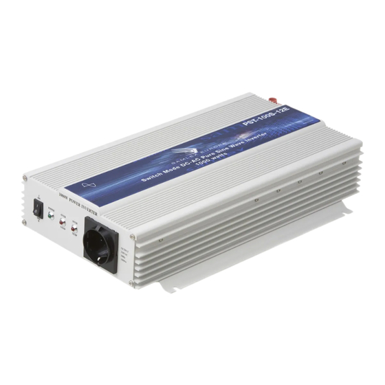
Summary of Contents for Samlex Europe PST-100S-12E
- Page 1 PURE SINEWAVE INVERTER Switch Mode Pure Sinewave Inverter Model No. PST-100S-12E PST-100S-24E PST-150S-12E PST-150S-24E PST-200S-12E PST-200S-24E OWNER’S MANUAL Please read this manual before operating your inverter...
-
Page 2: Table Of Contents
Specifying Batteries, Chargers and Alternators ....14,15, 16, 17 Installation ..............18, 19, 20, 21, 22 Operation..................23, 24 Protection Against Abnormal Conditions ........24, 25 Troubleshooting Guide ..............26, 27 Specifications ................28, 29, 30 Warranty ....................31 ©2009 Samlex Europe b.v. page 1... -
Page 3: Safety Instructions
S AF ETY I NS T RU CT IO NS Please read these instructions before installing or operating the inverter to prevent personal injury damage to the inverter GENERAL Installation and wiring compliance - Installation and wiring must comply with the local and national electrical codes and must be done by a certified electrician Preventing electrcal shock - Always connect the grounding connection on the inverter to the appropriate grounding... - Page 4 INVERTER RELATED Preventing paralleling of the AC output. The AC output of this inverter cannot be synchonised with another AC source and hence, it is notsuitable for paralleling. The AC output of the inverter should never be connected directly to an electrical breaker panel / load center which is also fed from the utility power / generator.
-
Page 5: Inverters - General Information
INVERTERS - GENERAL INFORMATION Why an inverter is needed The utiliti grid supplies you with alternating current (AC) electricity. AC is the standard form of electricity for anything that “plugs in” to the utility power. Direct current (DC) electricity flows in a single direction. Batteries provide DC electricity. AC alternate its direction many times per second. - Page 6 Loads that require “surge power” to start Resistive types of loads (like incandescent lamps, toaster, coffee maker, electric range, iron etc) do not require extra power to start. Their starting power is the same as their running power. Some loads like induction motors and high inertia motor driven devices will initially require a very large starting or “surge”...
- Page 7 Power rating of Microwaves The power rating of the microwave generally refers to the cooking power. The electrical power consumed by the microwave will beapproximately 2 times the cooking power. The “surge power” of the inverter should be 2 times the electrical power (i.e., 4 times the cooking power).
-
Page 8: Characteristics Of Sinusoidal Ac Power
CHARACTERISTICS OF SINUSOIDAL AC POWER Voltage, current, power factor, types of loads The voltage wave form of 230VAC, 50 Hz mains / utility power is like a sinewave. In a voltage with a sinewave-form, the instantaneous value and polarity of the voltage varies with respect to time and the wave-form is lijke a sine wave. -
Page 9: Advantage Of Sine Wave Inverters
ADVANTAGES OF A PURE SINE-WAVE INVERTER OVER A MODIFIED SINE-WAVE INVERTER The output voltage of a sine-wave inverter has a sine wave-form like the sine wave-form of the mains / utility voltage. In a sine wave, the voltage rises and falls smoothly with a smoothly changing phase angle and also changes its polarity instantly when it crosses 0 Volts. -
Page 10: Ac Power Distribution And Grounding
AC POWER DISTRIBUTION AND GROUNDING CAUTION: PLEASE NOTE THAT THE AC OUTPUT CONNECTIONS AND THE DC INPUT CONNECTIONS ON THESE INVERTERS ARE NOT CONECTED (BONDED) TO THE METAL CHASSIS OF THE INVERTER. BOTH THE INPUT AND OUTPUT CONNECTIONS ARE ISOLATED FROM THE METAL CHASSIS AND FROM EACH OTHER SYSTEM GROUNDIN G, AS REQUIRED BY NATIONAL / LOCAL ELECTRICAL CODES / STANDARDS, IS THE RESPONSIBILITY OF THE USER / SYSTEM INSTALLER... -
Page 11: Limiting Electromagnetic Interference (Emi)
Grounding to earth or to other designated ground. For safety, the metal chassis of the inverter is required to be grounded to the earth ground or to the other designated ground (for example, in a mobile RV, the metal frame of the RV is normally designated as the negative DC ground). - Page 12 POWERING DIRECT / EMBEDDED SWITCHED MODE POWER SUPPLY (SMPS) Non-linear nature of current drawn by Switched Mode Power Supplies. Power supplies are used to convert AC voltages like 230 VAC to various DC voltages like 3.3 V, 5 V, 12 V, 24 V, 48 V etc. Majority of modern day electronic devises use embedded general purpose Switch Mode type of Power Supplies (SMPS) to drive the electronic circuitry.
-
Page 13: Principle Of Operation
PRINCIPLE OF OPERATION The inverter converts the DC voltage of the battery to 120V, 60 Hz. AC voltage. The voltage conversion takes place in two stages. In the first stage, the DC voltage of the battery is converted to a high voltage DC using high frequency switching and Pulse Width Modulation (PWM) technique. -
Page 14: Specifying Batteries, Chargers And Alternators
SPECIFYING BATTERIES, CHARGERS & ALTERNATORS The inverter will require Deep Cycle Lead Acid Batteries of appropriate capacity. Lead-acid batteries can be categorized by the type of application: automotive service- Starting / Lighting / Ignition (SLI, a.k.a. cranking) and deep cycle service. SLI Batteries Everybody is familiar with the SLI batteries that are used for automotive starting and powering vehicular accessories SLI batteries are designed to produce high power... - Page 15 Typical battery sizes Below is a chart of some battery sizes applicable for powering inverters: BCI* Group Battery Voltage, V Battery AH 27 /31 GC2** * Battery Council International ** Golf Cart Reduction in usable capacity at higher dischargerates. As stated above, the rated capacity of the battery in AH is applicable at a discharge rate of 20 hours.
- Page 16 Depth of discharge and battery life The more deeply a battery is discharged on each cycle, the shorter the battery life. Using more batteries than the minimum required will result in longer life for the battery bank. A typical cycle life chart is given at Table 2 below: Table 2.
- Page 17 Sizing the Inverter Battery Bank. One of the most frequently asked question is, “how long will the batteries last? This question cannot be answered without knowing the size of the battery system and the load on the inverter. Usually this question is turned around to ask ”How long do you want your load to run?”, and then specific calculation can be done to determinate the proper battery bank size.
- Page 18 Charging Batteries The batteries can be charged by using good quality AC powered battery charger or from alternative energy sources like solar panels, wind or hydro systems. Make sure an appropriate battery charge controller is used. It is recommended that the batteries may be charged at 10% to 13 % of the Ampere Hour capacity (20 hour discharge rate).
-
Page 19: Installation
INSTALLATION GENERAL Installation and wiring compliance - Installation and wiring must comply with the local and the national electrical codes and must be done by a certified electrician. - In building / residential applications, electrical codes do not allow permanent connection of AC distribution wiring to the inverter’s AC output receptacles. - Page 20 DC SIDE CONNECTIONS The DC input power to the inverter is derived from deep cycle batteries of the required capacity. Read under “Specifying Batteries, Chargers and Alternators” on page 14 for details on sizing and charging of batteries. Preventing input over voltage It is to be ensured that the input voltage of the inverter does not exceed 16.5 VDC (for 12V version or 33 VDC (for 24V version) to prevent permanent damage to the inverter.
- Page 21 2 times the distance between the inverter and the battery assuming that two ( one positive and one negative)cables are used for the connection ) Distance up to 120cm Distance up to 180cm Ampere rating of fuse PST-100S-12E 35 Mmq 50 Mmq 200 A PST-100S-24E...
- Page 22 DC input terminals The DC input terminals have a tubular hole with a set screw. A suitable pin type of copper terminal should, therefore, be used on the cable end. Do not insert the stranded bare end of the cable directly into the tubular hole as the set screw will not pinch all the strands and will thus make only a partial and loose contact.
- Page 23 AC output connections The inverter uses standard VDE European receptacle for connecting the AC output to devices and appliances fitted with a 2-pin Schuko plug. In this VDE receptacle, two round slots are connected to the current-carrying conductors of the AC power source inside the inverter.
-
Page 24: Operation
OPERATION Powering on the loads After the inverter is switched on, it takes a finite time for it to become ready to deliver full power. Hence, always switch on the load(s) after a few seconds of switching on the inverter. Avoid switching on the inverter with the load already switched on. This may prematurely trigger the overload protection. -
Page 25: Protection Against Abnormal Conditions
Switching on / off using the optional remote on / off Control An optional corded Remote Control Model, No. RC-15, is available to enable switching on and off from a distance of 6 Mtr. The remote on / off control comeswith 6 Mtr. of wire. One end of the remote control is plugged into the 6 position modular jack (9) provided on the inverter. - Page 26 Shut-down due to reversal of polarity at the DC input terminals. The positive of the battery should be connected to the positive DC input terminal of the inverter, (the tip of the cigarette lighter plug), and the negative of the battery should be connected to the negative DC input terminal of the inverter (The spring loaded bow type contacts of the cigarette lighter plug).
-
Page 27: Troubleshooting Guide
TROUBLESHOOTING GUIDE SYMPTOM POSSIBLE CAUSE REMEDY On switching on, the green There is no voltage at 1 Check the continuity of the battery LED does not light. the DC input terminals input circuit. Buzzer is off. 2 Check that the battery fuse is intact. There is no AC voltage Replace if blown 3 Check that all connections in... - Page 28 SYMPTOM POSSIBLE CAUSE REMEDY There is no AC output. Shut-down due to high 1 Check that the voltage at the DC The green LED is off input DC voltage input terminals is less than 16.5V for Buzzer is on. (>16.5V for 12V version 12V model or 33V for 24V version or >...
-
Page 29: Specifications
SPECIFICATIONS PST-100S-12E PST-100S-24E Input Voltage ..........10.5 to 16.5 VDC......21 to 33 V DC Input Current at No Load ........... 1,2A......... 0,8A OutputVoltage ..........230VAC+/-3%......230VAC+/-3% Output Frequency............. 50 Hz........50 Hz Output Voltage Waveform ........ Sine Wave.......Sine Wave Total Harmonic distortion ........... <3%.........<3% Output Power -Continuous .............1000Watts*......1000 Watts*... - Page 30 SPECIFICATIONS PST-150S-12E PST-150S-24E Input Voltage ..........10.5 to 16.5 VDC......21 to 33 V DC Input Current at No Load .......... 1.6A..........1A OutputVoltage ..........230VAC+/-3%......230VAC+/-3% Output Frequency ........... 50 Hz ........50 Hz Output Voltage Waveform ......Sine Wave........Sine Wave Total Harmonic distortion ........
- Page 31 SPECIFICATIONS PST-200S-12E PST-200S-24E Input Voltage ..........10.7 to 16.5 VDC...... 21.4 to 33 V DC Input Current at No Load .......... 1.6A..........1A OutputVoltage ..........230VAC+/-3%......230VAC+/-3% Output Frequency ........... 50 Hz ........50 Hz Output Voltage Waveform ......Sine Wave........Sine Wave Total Harmonic distortion ........
-
Page 32: Warranty
2 YEAR Limited Warranty The sinewave inverter manufactured by Samlex Europe B.V. ( the “ Warrantor “ ) is warranted to be free from defects in workmanship and materials under normal use and service. This warranty is in effect for 2 years from the date of purchase by the user ( the “... - Page 33 www.samlex.com www.samlex-solar.com...
Need help?
Do you have a question about the PST-100S-12E and is the answer not in the manual?
Questions and answers