Table of Contents
Advertisement
Quick Links
GTD-2000ExW
Instruction Manual
Headquarters / Engineering research laboratory :
23 Gunpo Advance d Industry 1-ro(Bugok-dong), Gunpo-si, Gyeonggi-do
Tel +82-31-490-0800 Fax +82-31-490-0801
Yeongnam business office / Plant :
55 Gonghangap-gil 85beon-gil, Gangseogu, Busan Metropolitan City
Tel +51-973-8518 Fax +51-973-8519
E-mail : info@gastron.com
www.gastron.com
Read in detail for correct use.
Advertisement
Table of Contents

Related Manuals for GASTRON GTD-2000ExW


Summary of Contents for GASTRON GTD-2000ExW
- Page 1 Headquarters / Engineering research laboratory : 23 Gunpo Advance d Industry 1-ro(Bugok-dong), Gunpo-si, Gyeonggi-do Tel +82-31-490-0800 Fax +82-31-490-0801 Yeongnam business office / Plant : 55 Gonghangap-gil 85beon-gil, Gangseogu, Busan Metropolitan City Tel +51-973-8518 Fax +51-973-8519 E-mail : info@gastron.com www.gastron.com Read in detail for correct use.
- Page 2 We always seek to help our customers to find the product they need and we continuously research to develop a gas detector that satisfies our customers. From now on, you can solve all problems related to gas detectors with a GasTron product. We, GasTron, will be responsible for your satisfaction.
-
Page 3: Table Of Contents
GTD-2000ExW Contents Contents www.gastron.com Instruction Manual 04_05 1. Overview ······································································································································································ 7.2.1. Zero Calibration ······································································································································· 7.2.2. Span Calibration ······································································································································ 2. Configuration ······························································································································································ 7.3. ALARM MODE ··················································································································································· 3. Specifications ······························································································································································· 8. Troubleshooting ·························································································································································· 3.1. Basic Specification ·············································································································································· 8.1. Fault List ····························································································································································· 3.2. -
Page 4: Overview
Measuring Type Diffusion GTD-2000ExW flammable gas detector is installed in areas with gas leak hazards and continuously monitors gas leak. It - LCD or OLED Display displays measurements on LCD of the detector, converts and transmits data in DC 4~20 mA standard output signal. Also,... -
Page 5: Electrical Specifications (Standard Type)
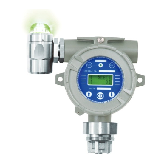
CVVS or CVVSB with shield Cable Connection Length Analog 2500m EMC Protection: Complies with EN50270 [Figure 2. GTD-2000ExW Components] NAME DESCRIPTIONS Housing Body Protects PCB Board built in Sensor and Housing from external environmental change and shock. 3.4. Environmental Specifications Housing Cover Top surface is built with circular glass to enable monitoring of measurement displayed on LCD. -
Page 6: Lamp Function Description
It is a multi-color LED that displays status. It serves to fix parts to the compliment part. SHAFT BODY It serves to fix parts to the opponent. CABLE WIRE It supplies power and transmits data. [Table 1. GTD-2000ExW Transmitter Components Description]... -
Page 7: Installation
GTD-2000ExW 5. Installation 5. Installation www.gastron.com Instruction Manual 12_13 It is prohibited for an individual, other than an approved user or a technician responsible for installation and repair from 5.2. Main PCB Configuration the head office, to install a gas leak detector on site or open the cover of the installed gas leak detector and manipulate ■ After detaching the display parts, the Main PCB terminal layout appears as shown in the figure below. -
Page 8: Wiring For 4~20Ma Source Operation Type
GTD-2000ExW 5. Installation 5. Installation www.gastron.com Instruction Manual 14_15 ■ Using CN5, CN6, and CN7 shown in the layout above, HART option board can be attached and 3ØScrew holes 5.2.1. Wiring for 4~20mA Source Operation Type located at top left of HART option board are used for fixing. ■ Connect 4-20 mA signal terminal at PLC side to 'mA' ■ After disassembling display parts, there is a terminal block in the Main PCB as shown in the figure below. Holding of GTD-2000Ex. GND terminal is used in common it with hands and pulling towards ceiling detaches it from the Main PCB. -
Page 9: Wiring For 4~20Ma 3Wire Sink Operation Type
■ Connect (+) and (-) terminals for 4-20 mA sink output at PLC side to VISO terminal and power (24V DC) (-) terminal, respectively. Connect 'mA' terminal of GTD-2000ExW to 'GND' terminal. Then, turn off the J1 jumper. [Figure 9. 4-20mA 3Wire Sink Configuration] [Figure 10. Calculation of GTD-2000ExW Installation Cable Length] ■ Power cable installation for each cable type is as shown in the table below. -
Page 10: Detector Operation Flow
- When GTL100 explosion-proof warning light is installed, upon an event of alarm1, red LED and buzzer [ %LEL] [Figure 11. GTD-2000ExW Mode Configuration] flicker and run in 1 sec interval. Upon an event of alarm2, they continuously run without flickering. -
Page 11: Menu Configuration Table
GTD-2000ExW 6. Detector Operation Flow 7. System Mode www.gastron.com Instruction Manual 20_21 6.4. Menu Configuration Table 7.1. Program Mode LEVEL2 LEVEL1 DEFAULT PASSWORD - Contacting "FUNC" key with the Magnet-bar for 2 sec or longer in Measuring Mode enters Password mode. NAME PARAMETER [**] - After setting Password using "↑" or "↓" key, contact "FUNC" key. GAS TYPE (Gas Type) [DEFIN./USER] DEFIN. - If password is correct, it enters Program mode. -
Page 12: System Mode
GTD-2000ExW 7. System Mode 7. System Mode www.gastron.com Instruction Manual 22_23 7.2. Calibration Mode 7.2.2. Span Calibration ■ Due to characteristics of the gas detector, minimum 30 min of stabilization time is required and maintenance - Contact "↑" or "↓" key to select "Calibration Mode". CALIBRA. - Contact "FUNC" key when "CALIBRA. MODE" is displayed to enter Calibration Mode. condition may change depending on site condition. MODE - Contact "RESET" key to return to Measuring Mode CALIBRA. 7.2.1. Zero Calibration - Contact "↑" or "↓" key to achieve [SPAN] then contact "FUNC" key to enter Span Calibration Mode. [SPAN] PASSWORD SPAN CAL - Contacting "FUNC" key with the Magnet-bar for 2 sec or longer in Measuring Mode enters Password mode. -
Page 13: Alarm Mode
GTD-2000ExW 7. System Mode 7. System Mode www.gastron.com Instruction Manual 24_25 7.3. ALARM MODE A2 TYPE It is a mode that sets operational direction of Alarm2. Contact "↑" or "↓" key to display "INC" or "DEC". [INC] "INC" mode operates when the value is equal or larger than set alarm threshold. "DEC" mode operates when PASSWORD Contacting "FUNC" key for 2 sec or longer in Measuring Mode enters Password mode. the value is equal or less than set alarm threshold. [**] After setting Password using "↑" or "↓" key, contact "FUNC" key. A2 TYPE Contact "FUNC" key when a desired mode is displayed to set then enter the next mode. [DEC] Contact "↑" or "↓" key to select "Alarm Mode". ALARM Contact "FUNC" key when "ALARM MODE" is displayed to enter Alarm setting mode. -
Page 14: Troubleshooting
2) Change sensor unit when the same problem occurs again Defective MPU inside Transmitter Change Transmitter Main Board Poor Sensor Output Status Change Sensor Check Input Power Noise Check External Input Voltage Noise Status [Table 6. Recovery List] [Figure 12. GTD-2000ExW Standard Type Drawing]... -
Page 15: Warning Light Gtl-100
GTD-2000ExW 9. Drawings and Dimensions 9. Drawings and Dimensions www.gastron.com Instruction Manual 28_29 9.2. Warning Light GTL-100 9.3. When Connecting Warning Light [Figure 13. GTL-100 Drawing] [Figure 14. GTD-2000Tx Warning Light Connection Drawing]... -
Page 16: Precautions Before Installation
GTD-2000ExW 10. Precautions before Installation 10. Precautions before Installation www.gastron.com Instruction Manual 30_31 10.1. Selecting a Place for Installation (Occupational Health & Safety Act Data) ■ During wiring work, use explosion-proof cable gland at cable inlet or tightly seal cable conduit during metal cable wiring construction to prevent spread of flames in case of explosion or movement of gas, etc. through the cable A gas leak detector alarm shall be installed in the following places. -
Page 17: Revision History
GTD-2000ExW 11. Revision History www.gastron.com Instruction Manual 32_33 VERSION CONTENTS DATE * Manual Initial Revision 2017.09.29...
Need help?
Do you have a question about the GTD-2000ExW and is the answer not in the manual?
Questions and answers