Table of Contents

Summary of Contents for H20 Distributors USRO4-100-QC-38
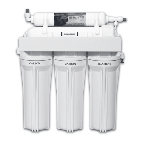
- Page 1 Installation and Service Guide Reverse Osmosis System with Quick-Connect Fittings USRO4-60-qc / USRO4-60-qc-38 / USRO4-100-qc-38 USRO5-60-qc / USRO5-60-qc-38 / USRO5-100-qc-38 Please read this manual carefully before attempting installation...
- Page 2 SyStem and Faucet dIaGram QUICK-CONNECT FITTINgS — HOw TO MaKE a CONNECTION Connecting standard quick-connect fittings Push up to pipe stop. Push the pipe into the fitting, to the pipe stop. The collet (gripper) has stainless steel teeth which hold the pipe firmly in position while the ‘O’ Ring provides a permanent leak proof seal.
- Page 3 Your Reverse Osmosis (RO) System has been tested and gently push in the tubing until it will not go any further. to ensure it will operate correctly. The following periodic To ensure that your tubing has made a snug fit, pull back maintenance is recommended so your system will provide gently on the tubing;...
-
Page 4: Unit Preparation
Procedures: A Drain Saddle is used to make a waste water connection 1. Mark the center with center punch for the 1/4” pilot with your drain under the sink. This is designed to fit hole. around a standard 1-1/2” OD drainpipe. The drain saddle 2. - Page 5 3. Self Piercing Valve and Tubing Installation 4. Drain Saddle Valve Installation (See Figure 3) The self-piercing valve, which is supplied, is designed for use with 3/8” to 1/2” OD copper or chrome plated A Drain Saddle is used to make a wastewater connection copper tubing, CPVC, &...
-
Page 6: System Start-Up
The RO unit is normally mounted to the right or left sink the RO system has been drained several times and the cabinet sidewall, depending on where supply tank is to be tank has a full supply of water. located. Generally the unit is installed at the front of the cabinet and the tank at the rear. -
Page 7: Membrane Replacement
4. Using the supplied housing wrench remove the filter higher pressures. They produce more water, faster, and housing. of better quality with high pressure. The vast majority of 5. Discard old filters. problems with RO Systems are a result of low pressure. 6. -
Page 8: Pressure Temperature Chart
PRESSURE TEMPERaTURE CHaRT Temp °F 0.2321 0.2653 0.2985 0.3316 0.3648 0.3979 0.4311 0.4643 0.4974 0.5306 0.5638 0.5969 0.6301 0.6632 0.6964 0.7296 0.2417 0.2762 0.3108 0.3453 0.3798 0.4144 0.4489 0.4834 0.5179 0.5525 0.5870 0.6215 0.6561 0.6906 0.7251 0.7597 0.2513 0.2872 0.3231 0.3590 0.3949 0.4308...


Need help?
Do you have a question about the USRO4-100-QC-38 and is the answer not in the manual?
Questions and answers