Table of Contents
Advertisement
Quick Links
Advertisement
Table of Contents

Summary of Contents for Nonin RespSense II LS1R
- Page 1 Operator’s Manual RespSense ™ Model LS1R Capnography Monitor English 0123 0123...
- Page 2 Follow Instructions for Use. Nonin makes no claim for use of the product other than those uses specified herein and disclaims any liability resulting from other uses. Observe all warnings, cautions, and notes. Unauthorized use, copying, or distribution of this manual is prohibited without written consent from Nonin Medical, Inc.
-
Page 3: Table Of Contents
Contents Indications for Use ..................1 Contraindications....................1 Warnings ........................ 1 Cautions ......................... 2 Guide to Symbols ..................5 Introduction....................7 About RespSense II....................7 About Capnometry....................7 Operator Requirements ..................7 System Components ..................8 RespSense II Monitor ..................... 9 Battery ........................ - Page 4 Contents (Continued) New PIN......................28 Factory Service....................28 Date/Time Screen ....................29 Alarm Lock Mode Screen..................30 Calibration Screen....................31 Calibration Procedure ..................31 Alarm Limit Settings ...................33 Alarm Limits ......................33 Alarms ......................35 High Priority Alarms ....................35 Medium Priority Alarms ..................36 Inoperable Alarms ....................37 Low Priority Alarms ....................37 Data Output and Software ................38 Device Memory .....................38 Download Patient Data ..................38...
- Page 5 Figure 3. Select Alarm Group Screen ..............15 Figure 4. Operating Screen ..................17 Figure 5. Start-up Screen ..................20 Figure 6. Access Configuration Menu (Nonin Logo) ..........24 Figure 7. Configuration Menu................... 24 Figure 8. Language/Units Screen................25 Figure 9. Responsible Organization Settings Screen..........26 Figure 10.
- Page 6 Tables Table 1. Symbols ....................... 5 Table 2. Monitor Features..................10 Table 3. Select Alarm Group Screen – Display Descriptions........16 Table 4. Operating Screen – Display Descriptions ..........17 Table 5. Alarm Limit Settings ................... 33 Table 6. High Priority Alarms ................... 36 Table 7.
-
Page 7: Indications For Use
Never allow liquids to enter into or to be spilled onto the monitor. If liquid has penetrated into the monitor, it must be checked by Nonin Technical Service. To avoid patient injury, only use Nonin-specified power supplies, cables, and accessories (see Accessories). The monitor displays a flashing yellow battery indicator (low battery) when it has approximately 60 minutes of use remaining before it shuts itself off. -
Page 8: Cautions
Indications for Use Warnings Prior to connecting the monitor to the power supply and a power outlet, be sure to verify the voltage and frequency rating on the power supply are the same as the outlet. If this is not the case, do not connect the monitor and power supply to the outlet. - Page 9 Do not attempt to replace the battery inside the monitor. The battery is not field replaceable and cannot be replaced by the operator. Use only Nonin-specified components. Use of another battery may present a risk of fire or explosion. Contact Nonin Technical Service when the battery needs replacing. Battery replacement by inadequately trained personnel could result in a hazardous situation.
- Page 10 Indications for Use Cautions (Continued) This equipment complies with IEC 60601-1-2 for electromagnetic compatibility for medical electrical equipment and/or systems. This standard is designed to provide reasonable protection against harmful interference in a typical medical installation. However, because of the proliferation of radio-frequency transmitting equipment and other sources of electrical noise in healthcare and other environments, it is possible that high levels of such interference due to close proximity or strength of a source might disrupt the performance of this device.
-
Page 11: Guide To Symbols
Guide to Symbols Guide to Symbols This chapter describes the symbols that are found on the system components and packaging. Table 1. Symbols Symbol Description/Function CAUTION! Follow Instructions for Use. CE Marking indicating conformance to EC Directive No. 93/42/EEC 0123 0123 concerning medical devices. - Page 12 Guide to Symbols Table 1. Symbols (Continued) Symbol Description/Function Temperature limitation for storage/shipping RoHS compliant (China) Date of manufacture Country of manufacture...
-
Page 13: Introduction
The sample lines can be used with or ® without Nafion tubing. Use only those accessories recommended by Nonin. Refer to the Accessories section for more information. The monitor has a touch screen display where settings and adjustments are made. The only buttons on the monitor, On/Standby (off) and Audio Pause, are located on the upper right corner of the front panel. -
Page 14: System Components
System Components System Components Carefully remove the monitor and accessories from the shipping carton. Save the packaging materials in case the monitor or accessories must be returned. Compare the packing list with the accessories received to make sure the shipment is complete. The standard system configuration includes these non-sterile components: •... -
Page 15: Respsense Ii Monitor
System Components RespSense II Monitor Front Side MEDICAL EQUIPMENT 0123 0123 MASS: 865g 12 VDC, 1.5A IP22 Nonin Medical, Inc. Plymouth, MN USA Use with Nonin Power Adapters Back Figure 1. Monitor Features... -
Page 16: Table 2. Monitor Features
System Components Table 2. Monitor Features No. Symbol/Name Description Touch Screen The monitor’s LCD displays parameters, graphs, menus, and other Display information.The display is a touch screen from which all operator-defined settings are made. See Display Screens section for additional screen information and descriptions. -
Page 17: Battery
The battery is rechargeable and charges itself whenever the monitor is connected to a power outlet, even when the monitor is turned off. Always connect the monitor to an outlet whenever it is not in use. Recharging a fully depleted battery takes approximately 9 hours when using a Nonin- specified power supply. -
Page 18: Battery Replacement
Battery Replacement The battery, made of Lithium Ion (Li-Ion) rechargeable cells, is integral to the device and cannot be replaced by anyone other Nonin Technical Service. The life expectancy of the battery is approximately 1 year. CAUTION: Do not attempt to replace the battery inside the monitor. The battery is not field replaceable and cannot be replaced by the operator. -
Page 19: Nafion Tubing
System Components Nafion Tubing The Nafion tubing is a single-use, disposable component designed to be placed between the moisture trap and the nasal cannula or sample line to remove water vapor. Attaching the Nafion Tubing 1. Connect male end of the Nafion tubing to the moisture trap. Turn clockwise to tighten. 2. -
Page 20: Psg Dac Cables
Refer to the individual PSG DAC cable instructions for use for more information. Capno RTC Cable Nonin’s Capno RTC digital USB cable transmits real-time data from the monitor to another device (e.g., computer). Refer to the Capno RTC instructions for use for more information. -
Page 21: Display Screens
Display Screens Display Screens The following section describes the icons and their functions on the select alarm group and operating screens. Select Alarm Group Screen NOTE: This screen does not display if the monitor has locked alarm limits (see Alarm Lock Mode Screen section). -
Page 22: Table 3. Select Alarm Group Screen - Display Descriptions
Display Screens Table 3. Select Alarm Group Screen – Display Descriptions Symbol Description Alarm Limits ≤30kg / 66lbs Pressing this icon selects the default alarm limits for patients weighing 30 kg (66 lbs) or less. • If the Responsible Organization Settings have not been set, the alarm limits will be the factory default settings (see table 5). -
Page 23: Operating Screen
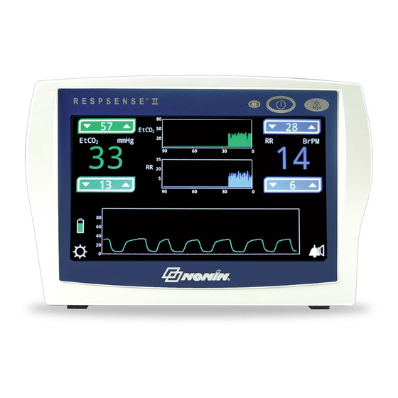
Display Screens Operating Screen The main operating screen (figure 4) displays parameters, graphs, and other information. NOTE: If a pop-up window displays while monitoring, the icons and alarm limit up/down arrows cannot be used until the pop-up window is closed. Figure 4. - Page 24 Display Screens Table 4. Operating Screen – Display Descriptions (Continued) Symbol/Name Description Displays the respiration rate in breaths per minute. BrPM EtCO Messages Shows capnometer alarm messages. See Alarms for more Example: information. Audible Alarm No symbol means audible alarms are enabled. A bell with dashed lines indicates that audible alarms are paused.
- Page 25 Display Screens Table 4. Operating Screen – Display Descriptions (Continued) Symbol/Name Description Brightness Allows the operator to change the brightness of the display. Options are maximum (default), medium, and low. Audible Alarm Volume Medium Allows the operator to change the audible alarm volume. The minimum alarm value is set on the Responsible Organization Maximum (default) Settings screen.
-
Page 26: Using The Respsense Ii Monitor
3. The Loading screen displays. NOTE: A green screen may briefly display while screens transition. 4. The Nonin logo start-up screen (figure 5) Figure 5. Start-up Screen displays with the monitor name. The lower left corner of the screen shows the monitor’s software revision. -
Page 27: Shut Down Modes
Using the RespSense II Monitor Shut Down Modes To conserve battery life, the monitor has two shut down modes – Standby mode and Deep Sleep mode. Start-up from Standby mode is slightly faster than start-up from Deep Sleep mode. Standby Mode The monitor enters Standby mode if the battery indicator at shut down is green or if the monitor is connected to a power supply. -
Page 28: Monitoring A Patient
4. Connect the sample line to the connector on the moisture trap and secure it by turning the Luer lock connector clockwise. Only use sample lines recommended by Nonin (see Accessories). 5. See Monitoring a Patient. -
Page 29: Adjusting Display Brightness
Using the RespSense II Monitor CAUTION: Set or adjust only one parameter at a time. WARNING: The device is intended only as an adjunct device in patient assessment. It must be used in conjunction with other methods of assessing clinical signs and symptoms. -
Page 30: Configuration Menu
2. Start-up sequence begins. 3. When the Nonin logo start-up screen displays, press the Nonin logo twice (double-tap). In figure 6, the Nonin logo is highlighted with a white box. 4. Configuration Menu (figure 7) displays. Figure 6. Access Configuration 5. -
Page 31: Language/Units Screen
Using the RespSense II Monitor Language/Units Screen This screen allows the operator to change the display language and the EtCO unit of measurement. This screen is accessed through the Configuration Menu (see Access the Configuration Menu). Defaults are English and mmHg. The available languages are: Dansk (Danish) English (default) Deutsch (German) -
Page 32: Responsible Organization Settings Screen
Using the RespSense II Monitor Responsible Organization Settings Screen This screen allows the operator to establish institution default high and low limits for EtCO respiration rate. This screen is accessed through the Configuration Menu (see Access the Configuration Menu). NOTES: •... -
Page 33: Minimum Alarm Volume
Using the RespSense II Monitor Minimum Alarm Volume This setting controls the monitor’s available audible alarm volume levels. The default minimum alarm volume is Medium. Set the Minimum Alarm Volume 1. Access the Responsible Organizations Settings screen. 2. In the Minimum Alarm Volume field, press one of the options. Options include Off, Medium (default), and Maximum. -
Page 34: Reset Device To Factory Defaults
Press OK to acknowledge and press New PIN again. 4. Press OK to save the new PIN. To exit without saving changes, press Cancel. 5. Display returns to the Responsible Organization Settings screen. Factory Service This feature is only used by Nonin Medical, Inc. -
Page 35: Date/Time Screen
Using the RespSense II Monitor Date/Time Screen This screen allows the operator to set the monitor’s date and time (24-hour clock). The date/time is used in the file name when downloading data. If the operator will not be downloading data, setting the date/time is not required. -
Page 36: Alarm Lock Mode Screen
Using the RespSense II Monitor Alarm Lock Mode Screen This screen allows the operator to set and lock the monitor’s alarm limits. NOTES: • The locked alarm limits cannot be set to limits outside of the Responsible Organization limits. • When alarm limits are locked, limits cannot be adjusted when monitoring. -
Page 37: Calibration Screen
Using the RespSense II Monitor Calibration Screen This screen is accessed through the Configuration Menu (see Access the Configuration Menu). Calibration Procedure The monitor has a built-in zero-point calibration function for CO . Perform the calibration procedure at least every 6 months, or if the baseline of the CO graph is elevated. - Page 38 (4.4 – 5.7 Vol%/kPa or 33 – 43 mmHg) an internal air leak is possible. Replace the single-use, disposable moisture trap and perform the calibration procedure. If the problem persists, contact Nonin Technical Service.
-
Page 39: Alarm Limit Settings
Alarm Limit Settings Alarm Limit Settings If not locked, the operator can increase or decrease the alarm limit settings for individual patients. The alarm limit settings may be restricted by the Responsible Organization Settings. • Press the up arrow to increase an alarm limit. •... - Page 40 Alarm Limit Settings CAUTION: Setting alarm limits to extremes can render the alarm system useless. CAUTION: The monitor is equipped with automatic barometric pressure compensation. End tidal pCO values displayed are calculated based on an atmospheric pressure of 760 mmHg and pH O of 47 mmHg (example: 760 –...
-
Page 41: Alarms
Alarms Alarms The monitor has audible and visual alarm indicators to alert the operator in case immediate patient attention is required or an equipment alarm occurs (figure 13). An audible or visual alarm remains active until the condition is no longer present. Each parameter can only have one high or low limit alarm at a time. -
Page 42: Medium Priority Alarms
Alarms Table 6. High Priority Alarms Alarm Visual Indicator Audible Indicator EtCO High Limit – displays when EtCO high limit flashes red 3 beeps, pause, EtCO is above the high alarm limit 2 times per second. 2 beeps, pause, 3 beeps, pause, 2 beeps, and a 6- EtCO Low Limit –... -
Page 43: Inoperable Alarms
1. Turn the monitor off and then back on again to remove the error message. 2. If the error persists, note the error code and contact Nonin Technical Service at (800) 356- 8874 (USA and Canada), +1 (763) 553-9968, or +31 (0)13 - 79 99 040 (Europe). -
Page 44: Data Output And Software
8 GB SDCZ71-008G-A46 Cruzer Blade™ 4 GB SDCZ50-004G-A46 NOTE: If USB flash drive performance issues occur, see the Troubleshooting section for more information before contacting Nonin. Nonin cannot guarantee USB flash drive performance if a recommended flash drive is not used. -
Page 45: Download Data From The Monitor
Data Output and Software Download Data from the Monitor NOTE: Data cannot be downloaded if there is a medium or high priority alarm. 1. With the monitor on, but not connected to a patient, connect a USB flash drive to the monitor. 2. -
Page 46: Data Format
Data Output and Software Data Format The download directory name is the monitor’s serial number (XXXXXXXXX) followed by the current date and time. Example: XXXXXXXXX_YYYY_MM_dd_hh_mm_ss NOTE: 1970 will display in the YYYY field if the date/time is not set. Within the directory, patient data records are downloaded using a comma separated values (.csv) format. -
Page 47: Monitor Software
LAL is the current lower alarm limit value for each parameter. Alarm volume is Off, Medium or Maximum. CRC is a 16-bit CCITT for the entire row. Monitor Software Visit nonin.com for more information about the monitor’s software, including the latest monitor software revision. -
Page 48: Connecting The Device Into A Medical System
Data Output and Software Connecting the Device into a Medical System Incorporating the device into a medical system requires the integrator to identify, analyze, and evaluate the risks to patient, operators, and third parties. Subsequent changes to the medical system after device integration could introduce new risks and will require additional analysis. Changes to the medical system that must be evaluated include: •... -
Page 49: Maintenance And Inspection
Maintenance Ensuring Optimal Performance In order to ensure safety and optimal performance of the monitor, Nonin recommends a yearly inspection and functional check be performed on the monitor (see Recommended Inspections and Functional Check). The inspection and functional check may be performed by Nonin Technical Services or at your facility. -
Page 50: Recommended Inspections And Functional Check
WARNING: Never allow liquids to enter into or to be spilled onto the monitor. If liquid has penetrated into the monitor it must be checked by Nonin Technical Service. CAUTION: Be careful not to drop the monitor on the floor or strike it against hard surfaces. -
Page 51: Troubleshooting
The table below lists common messages, descriptions, and actions to take. If these solutions do not correct the problem, please contact Nonin Technical Service at (800) 356- 8874 (USA and Canada), +1 (763) 553-9968, or +31 (0)13 - 79 99 040 (Europe). - Page 52 To prevent damage to the pump, the pump stops off. after 10 seconds of occlusion. See above for “OCCLUSION” message solutions. If the problem persists, contact Nonin Technical Service. Monitor has shut off. To avoid overheating, the See above for “OCCLUSION” message solutions.
- Page 53 This indicates Charge the monitor. Connect the monitor to the that a problem has power supply and the power supply to an outlet. occurred, possibly due to If the problem persists, contact Nonin Technical interference or software Service. issues. Low EtCO...
- Page 54 PIN is not the correct displays. length. The PIN entered does not Enter the default PIN (0000). match the Factory PIN or If 0000 is not the correct PIN, contact Nonin the Responsible Technical Service. Organization PIN.
-
Page 55: Accessories
9968, or +31 (0)13 - 79 99 040 (Europe) • Visit www.nonin.com Nonin may update the accessories list at any time. It is the purchaser’s responsibility to always ask for the current list, by model number, when ordering accessories. Item... - Page 56 Accessories Item Description Verification Gas Verification gas and tubing. Contains 5 Vol% of CO (equals 38 mmHg or 5.3 kPa). To be used with a gas valve. Gas Valve for Reusable gas valve and tubing for controlling the flow from the verification Verification Gas gas.
-
Page 57: Service, Support, And Warranty
Nonin warrants the RespSense II monitor for a period of 3 years from the date of purchase. Extended warranties are available on most Nonin devices. Please consult your local Nonin distributor for additional information. The device’s expected service life is 5 years. -
Page 58: Technical Information
Rated supply voltages or voltage ranges for the power supply 100 – 240 VAC 50 – 60 Hz Input voltage from the power supply 12 VDC, 1.5 A WARNING: To avoid patient injury, only use Nonin-specified power supplies, cables, and accessories (see Accessories). -
Page 59: Manufacturer's Declaration
Technical Information Manufacturer’s Declaration See the following tables for specific information regarding this device’s compliance to IEC 60601- 1-2. Table 10. Electromagnetic Emissions Emissions Test Compliance Electromagnetic Environment—Guidance This device is intended for use in the electromagnetic environment specified below. The user of this device should ensure that it is used in such an environment. -
Page 60: Table 11. Electromagnetic Immunity
Technical Information Table 11. Electromagnetic Immunity Electromagnetic Immunity Test IEC 60601 Test Level Compliance Level Environment—Guidance This device is intended for use in the electromagnetic environment specified below. The user of this device should ensure that it is used in such an environment. Electrostatic 3rd edition: 3rd edition:... -
Page 61: Table 12. Guidance And Manufacturer's Declaration-Electromagnetic Immunity
Technical Information Table 12. Guidance and Manufacturer’s Declaration—Electromagnetic Immunity IEC 60601 Immunity Test Compliance Level Electromagnetic Environment—Guidance Test Level This device is intended for use in the electromagnetic environment specified below. The user of this device should ensure that it is used in such an environment. Portable and mobile RF communications equipment should be used no closer to any part of the device, including cables, than the recommended separation distance calculated from the equation applicable to the frequency of the transmitter. -
Page 62: Equipment Response Time
Technical Information Table 13. Recommended Separation Distances This device is intended for use in an electromagnetic environment in which radiated RF disturbances are controlled. Customers or users of this device can help prevent electromagnetic interference by maintaining a minimum distance between portable and mobile RF communication equipment (transmitters) and the device as recommended below, according to maximum output power of the communications equipment. -
Page 63: System Specifications
Technical Information System Specifications Power Requirements: Power Supply: 100 – 240 VAC 50 – 60 Hz Power Consumption: 3.6 W with battery operation 9 W with power supply Input: 12 VDC, 720 mA Internal Battery: Type: Lithium Ion (Li-Ion) internal battery, non-field replaceable, rechargeable Battery Capacity: Approximately 5 hours Charging Time: Approximately 9 hours... -
Page 64: Capnography Specifications
Technical Information Capnography Specifications Respiration Range: 0 to 99 respirations/minute Respiration Accuracy: 3 to 50 respirations/minute ±2 51 to 60 respirations/minute ±3 EtCO Range: 0 to 99 mmHg (0 to 13.2 kPa) EtCO Accuracy: ±0.2 kPa / ±2 mmHg, +8% of reading* 540 –...
Need help?
Do you have a question about the RespSense II LS1R and is the answer not in the manual?
Questions and answers