
Related Manuals for Motomaster 009-1011-0


Summary of Contents for Motomaster 009-1011-0
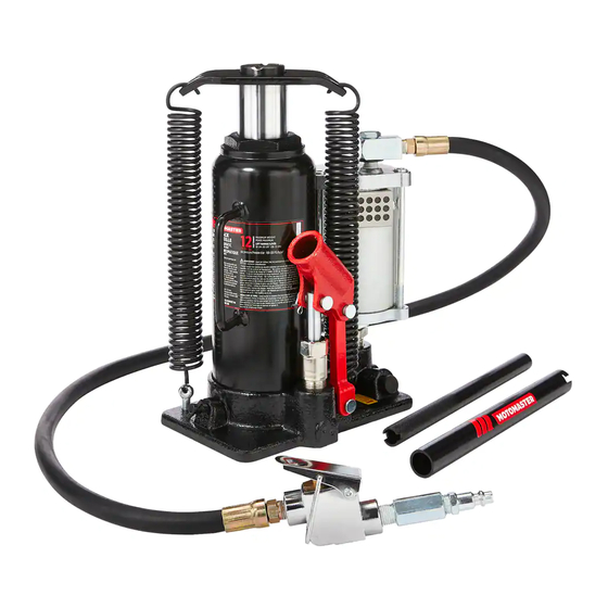
- Page 1 009-1011-0 HYDRAULIC / PNEUMATIC JACK IMPORTANT: To prevent serious injury, read and understand all warnings and instructions before use.
- Page 2 009-1011-0 1-888-942-6686 IF ANY PARTS ARE MISSING DAMAGED, OR IF YOU HAVE ANY QUESTIONS, PLEASE CALL OUR TOLL-FREE HELPLINE AT 1-888-942-6686 Read and understand this instruction manual thoroughly before using the product. It contains important information for your safety as well as operating and maintenance advice.
-
Page 3: Table Of Contents
TABLE OF CONTENTS Speci cations General Safety Precautions Unpacking Unpacking Assembly Before operating this lift Checking hydraulic uid Bleeding the System Operation Maintenance Troubleshooting Hydraulic Jack Assembly Diagram Hydraulic Jack Parts List Warranty SAVE THESE INSTRUCTIONS This manual contains important safety and operating instructions. Read all instructions and follow them while using the product. -
Page 4: Speci Cations
009-1011-0 1-888-942-6686 SPECIFICATIONS Construction Formed Steel over Maximum Lifting 12 Tons (10,884 kg) Hydraulic action Capacity Lift Range 10 1/4 - 20 1/8" Screw Extension 3 5/32" (8 cm) (26 - 51 cm) Hydraulic Lift 6 3/4" (17 cm) Overall Base 8 1/2"... - Page 5 • Store idle jacks out of reach of children and other untrained persons. Jacks are dangerous in the hands of untrained users. • Maintain jacks with care. Do not use a damaged jack. Tag damaged jacks and do not use until repaired. •...
- Page 6 009-1011-0 1-888-942-6686 . 009-0037-6 • Make sure the jack is used only on a dry, oil/grease-free, flat, level, solid surface capable of supporting the weight of the vehicle being lifted and any additional tools and equipment. • Use the jack only on vehicles whose frames have lifting points (on their seam or frame) capable of aligning with the saddle of the jack.
- Page 7 • Lift vehicle only by manufacturer-recommended lifting points. • Stay out from under load while being lifted or supported. • Bleed hydraulic system before use. • Use only for lifting. • Do not exceed the maximum air pressure. Capacity for this jack is 120 PSI. •...
-
Page 8: Unpacking
009-1011-0 1-888-942-6686 . 009-0037-6 UNPACKING When unpacking, check for damage. If any parts are missing or broken, please call Customer Service at the number on the cover of this manual. • Hydraulic/Pneumatic Jack • Attached 49" air hose with fittings •... -
Page 9: Bleeding The System
BLEEDING THE SYSTEM • Remove the oil filler plug (16). Insert the slot on the lower portion of the handle (54) over the release valve (4). Turn the handle assembly clockwise to close the release valve (4). • Insert the handle assembly into the handle bracket (31). Pump the handle (54) 10-15 times. -
Page 10: Operation
009-1011-0 1-888-942-6686 . 009-0037-6 OPERATION • Verify that the vehicle’s weight is not more than the weight capacity for this jack. • Check to make sure the jack is fully lowered. If not, insert the lower portion of the handle into the release valve and turn the handle counter-clockwise to lower the jack. - Page 11 • To lower the item, first lift the item slightly and remove the jack stands. • Engage notches in the end of the jack handle (54) onto the release valve (4). Turn the valve slightly, approximately 1/4 turn to lower the load. When the load is lowered, turn the release valve clockwise to stop the motion.
-
Page 12: Maintenance
009-1011-0 1-888-942-6686 MAINTENANCE • Oil Replacement a. Place the jack in an upright position. b. Completely lower the ram (13). Remove the oil filler plug (16). c. Fill with high quality hydraulic jack oil to the lower rim of the fill hole. -
Page 13: Troubleshooting
TROUBLESHOOTING • If the jack fails to lift, or fades under the load, first check that the release valve (4) is closed. Engage the notches at the end of the jack handle (54) onto the release valve (4) and turn clockwise. Check to see if this has solved the problem. •... - Page 14 009-1011-0 1-888-942-6686 NOTE: Some parts are listed and shown for illustration purposes only and are not available individually as replacement parts.
-
Page 15: Hydraulic Jack Parts List
HYDRAULIC JACK PARTS LIST No. Description Qty. No. Description Qty. Base Ball Ball Ball Cup Seal Spring Release Valve Screw Ball Cup O-ring Spring Screw Spring Plastic Cap Screw Air Motor Assembly Nylon Ring Air Supply Hose Cylinder Lock Lever O-ring Lever Cup Seal... -
Page 16: Warranty
(1) year warranty against defects in workmanship ® and materials. At its discretion, MotoMaster Canada agrees to have any defective part(s) repaired or replaced free of charge, within the stated warranty period, when returned by the original purchaser with proof of purchase. This product is not guaranteed against wear or breakage due to misuse and/or abuse. - Page 17 Modèle n 009-1011-0 CRIC HYDRAULIQUE/PNEUMATIQUE GUIDE IMPORTANT : Pour réduire les risques de blessures graves, lisez et assimilez tous les avertissements et les D’UTILISATION consignes avant l’utilisation.
- Page 18 Modèle n 009-1011-0 / Communiquez avec nous : 1-888-942-6686 SI VOUS AVEZ DES QUESTIONS AU SUJET DE CET ARTICLE, OU SI DES PIÈCES SONT MANQUANTES OU ENDOMMAGÉES, COMMUNIQUEZ AVEC NOTRE SERVICE D'ASSISTANCE TÉLÉPHONIQUE SANS FRAIS AU 1-888-942-6686. Veuillez lire attentivement et bien comprendre le présent guide avant d'utiliser cet article.
- Page 19 TABLE DES MATIÈRES Fiche technique Consignes de sécurité générales Déballage Déballage Montage Avant d’utiliser ce cric Véri cation du liquide hydraulique Purge du système Fonctionnement Entretien Dépannage Schéma de montage du cric hydraulique Nomenclature du cric hydraulique Garantie CONSERVEZ CES CONSIGNES Le présent guide contient d'importantes consignes de sécurité...
-
Page 20: Fiche Technique
Modèle n 009-1011-0 / Communiquez avec nous : 1-888-942-6686 FICHE TECHNIQUE Construction Profilé en tôle Capacité de charge 12 tonnes (10 884kg) pliée sur action maximale hydraulique Delete Delete Levée 10 1/4 à 20 1/8 po Vis de rallonge 3 5/32 po (8 cm) (26 à... - Page 21 • Ne forcez pas le cric. Utilisez le cric adapté à l'usage que vous comptez en faire. Pour plus d’efficacité et de sûreté, il est préférable d’utiliser le cric en respectant sa capacité nominale. • Rangez les crics non utilisés hors de la portée des enfants et à l’écart de toute personne ne sachant pas s'en servir.
- Page 22 Modèle n 009-1011-0 / Communiquez avec nous : 1-888-942-6686 . 009-0037-6 • Lorsque vous levez complètement l’extrémité avant ou arrière d’un véhicule, assurez- vous de soutenir la charge immédiatement à l’aide de deux chandelles. Alignez le support des chandelles directement sous le chàssis du véhicule ou sous les points d’appui recommandés.
- Page 23 • N’ajustez jamais la soupape de sûreté réglée en usine. • Air comprimé seulement. N’utilisez jamais de gaz comprimé pour actionner cet article. • Placez-le seulement aux points de levage recommandés pas le constructeur du véhicule. • Ne vous glissez jamais sous la charge en cours de soulèvement et tenez-vous en éloigné. •...
-
Page 24: Déballage
Modèle n 009-1011-0 / Communiquez avec nous : 1-888-942-6686 . 009-0037-6 DÉBALLAGE Lorsque vous déballez votre cric, vérifiez si des pièces sont endommagées. Si des pièces sont manquantes ou brisées, veuillez communiquer avec le service à la clientèle au numéro se trouvant sur la page couverture du présent guide. -
Page 25: Purge Du Système
PURGE DU SYSTÈME • Retirez le bouchon de remplissage (16). Placez la fente pratiquée dans la partie inférieure du manche (54) sur la soupape d'arrivée/retour (4). Faites tourner le manche dans le sens horaire pour fermer la soupape d'arrivée/retour (4). •... -
Page 26: Fonctionnement
Modèle n 009-1011-0 / Communiquez avec nous : 1-888-942-6686 . 009-0037-6 FONCTIONNEMENT • Assurez-vous que le poids du véhicule n’excède pas la capacité de charge du cric. • Assurez-vous que le cric est complètement descendu. Si ce n’est pas le cas, insérez la partie inférieure du manche dans la soupape d’arrivée/retour, et tournez le manche... - Page 27 • Utilisez des chandelles (non comprises) ou un autre moyen pour soutenir la charge. Ne laissez pas la charge sur le cric pendant une période prolongée. Cette omission pourrait entraîner des blessures graves ou des dommages matériels. • Pour faire descendre la charge, soulevez-la légèrement et retirez les chandelles. •...
-
Page 28: Entretien
Modèle n 009-1011-0 / Communiquez avec nous : 1-888-942-6686 . 009-0037-6 ENTRETIEN • Changement d’huile a. Placez le cric à la verticale. b. Faites descendre complètement le vérin (13). Retirez le bouchon de remplissage (16). c. Remplissez le réservoir avec de l’huile hydraulique à cric de qualité supérieure jusqu’au bord inférieur de l’orifice de remplissage. -
Page 29: Dépannage
DÉPANNAGE • Si le cric ne monte pas ou s’affaiblit sous une charge, vérifiez d’abord si la soupape d’arrivée/retour (4) est fermée. Insérez les encoches dans l’extrémité du manche du cric (54) dans la soupape d’arrivée/retour (4) et tournez dans le sens horaire. Vérifiez si cette mesure a réglé... - Page 30 009-1011-0 1-888-942-6686 Modèle n 009-1011-0 / Communiquez avec nous : 1-888-942-6686 REMARQUE: Certaines pièces sont énumérées et présentées à des ns d’illustration uniquement, et ne sont pas offertes à l’unité comme pièces de rechange.
-
Page 31: Nomenclature Du Cric Hydraulique
NOMENCLATURE DU CRIC HYDRAULIQUE Nº Description Qté Nº Description Qté Base Bille Bille Cuvette à billes Bague d’étanchéité Ressort Soupape d’arrivée/retour 1 Cuvette à billes Joint torique Ressort Ressort Capuchon en plastique Moteur pneumatique Bague en nylon Tuyau d'arrivée d'air Cylindre Levier de verrouillage Joint torique... -
Page 32: Garantie
Cet article MotoMaster comprend une garantie d’un (1) an contre les défauts de fabrication et de matériau(x). MotoMaster Canada consent, à sa discrétion, à réparer ou à remplacer toute pièce défectueuse sans frais au cours de la période de garantie convenue lorsque l’article, accompagné...
Need help?
Do you have a question about the 009-1011-0 and is the answer not in the manual?
Questions and answers