Table of Contents
Advertisement
Quick Links
Advertisement
Table of Contents

Related Manuals for Loopcomm LP-7615

Summary of Contents for Loopcomm LP-7615
- Page 1 802.11n Wireless PCI Adapter USER MANUAL 1.0.0 © 2010...
-
Page 2: Table Of Contents
Table of Contents Chapter I Introduction 1. Welcome ........................... 2. Product Feature ........................... 3. Contents of Package ........................... 4. Before you begin ........................... Chapter II Designing Your PCI Adapter Chapter III Installation 1. Install Your PCI Adapter ........................... 2. Install Driver and Utility ........................... - Page 3 2.9. Link Status ..............................71 3. Security ........................... 3.1 Auth. \ Encry. Setting - WEP/TKIP/AES ................................. 73 3.2 802.1x Setting ................................. 73 3.3 Example to Reconnect 802.1x Authenticated Connection after 802.1x Authenticated connection Is Failed in Profile ................................. 76 3.4 Example to Configure Connection with WEP on .................................
-
Page 4: Chapter I Introduction
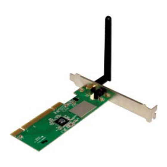
Introduction Welcome PCI Adapter connects you with IEEE802.11n(Draft 2.0) networks at receiving rate up to an incredible 150Mbps! By using the reflection signal, 802.11n technology increases the range and reduces “dead spots” in the wireless coverage area. Unlike ordinary wireless networking of 802.11b/g standards that are confused by wireless reflections, 802.11n can actually use these reflections to increase four times transmission range of 802.11g products. -
Page 5: Designing Your Pci Adapter
Designing Your PCI Adapter Designing Your PCI Adapter PCI Adapter supports up to 150Mbps connections. It is fully compliant with the specifications defined in 802.11n (Draft 2.0) standard. The status LED indicators of PCI Card are described in the following. •... -
Page 6: Install Driver And Utility
Install Driver and Utility NOTE: Snap-shot screens of the following installation procedure are based on Windows XP. Installation procedures will be similar for other windows operating systems. 1. Insert Installation CD to your CD-ROM drive. And click Driver Installation. The wizard will run and install all necessary files to your computer automatically. - Page 7 Installation 3. Click Next.
- Page 8 4. Select Ralink Configuration Tool or Microsoft Zero Configuration Tool then click Next. a. It’s recommended to select Ralink Configuration Tool, which provides fully access to all function of PCI Adapter. b. If you prefer to use the wireless configuration tool provided by Windows XP or Vista, please select Microsoft Zero Configuration Tool.
- Page 9 Installation...
- Page 10 5. Click Finish to complete the software installation. -10-...
-
Page 11: Utility Config
Installation Utility Config 4.1.1 Ralink Wireless Utility (RaUI) or Windows Zero Configuration (WZC) Windows XP includes a wireless configuration utility named "Windows Zero configuration" (WZC) which provides basic configuration functions to the Ralink Wireless NIC. Ralink's utility (RaUI) additionally provides WPA functionality. To make it easier for the user to select the correct utility. -
Page 12: Use Wzc To Configure Wireless Nic
Figure 1-3 RaUI status with WZC active When activating WZC, there are several difference with the RaUI status, compared to the RaUI status without WZC running. The profile button will be gray. Profile functionality is removed since the NIC is controlled by WZC. - Page 13 Utility Config Figure 1-4 status prompt for no connection Right-click the network connection icon in taskbar. Figure 1-5 Select WZC main status Select "View Available Wireless Networks" and the "Wireless Network Connection" dialog box will pop up, as shown in Figure 1-6. Figure 1-6 Wireless Network Connection Select the intended access point and click "Connect".
- Page 14 Figure 1-7 Select intended AP : AP1, then click "Connect" -14-...
- Page 15 Utility Config Figure 1-8 Connect AP : AP1 successfully If you want to modify information about the AP, click "Change advanced settings" as shown in Figure 1-9. Then select the "Wireless Networks" tab shown as Figure 1- Figure 1-9 Click "Change advanced settings" -15-...
- Page 16 Figure 1-10 Choose the "Wireless Networks" tab Click "Properties" as shown in Figure 1-11. Then click "OK" button. -16-...
- Page 17 Utility Config Figure 1-11 AP's properties After filling in the appropriate value, click "OK." The pop-up will indicate the status. as shown in Figure 1-12. Figure 1-12 Network connection status Clicking the Ralink icon will bring up the RaUI main window. Users can find the surrounding APs in the list.
-
Page 18: Raui
Figure 1-13 Show connection status by using WZC to initiate the connection RaUI 4.2.1 Start 4.2.1.1 Start RaUI When starting RaUI, the system will connect to the AP with best signal strength without setting a profile or matching a profile setting. When starting RaUI, it will issue a scan command to a wireless NIC. - Page 19 Utility Config Figure 2-1-1 RaUI section introduction There are three sections to the RaUI dialog box. These sections are briefly described as follow. Button Section: Include buttons for selecting the Profile page, Network page, Advanced page, Statistics page, WMM page, WPS page, the About button, Radio On/Off button and Help.
- Page 20 Function Section: Appears to present information and options related to the button. Figure 2-1-5 Profile page Figure 2-1-6 Network page Figure 2-1-7 Advance page -20-...
- Page 21 Utility Config Figure 2-1-8 Statistics page Figure 2-1-9 WMM page Figure 2-1-10 WPS page -21-...
- Page 22 Figure 2-1-11 About page Status Section: This section includes information about the link status, authentication status, AP's information and configuration, and retrying the connection when authentication is failed. Figure 2-1-12 Link Status Figure 2-1-13 Authentication Status -22-...
- Page 23 Utility Config Figure 2-1-14 AP's Information Figure 2-1-15 Retry the connection Figure 2-1-16 Configuration When starting RaUI, a small Ralink icon appears in the notifications area of the taskbar, as shown in Figure 2-1-15. You can double click it to maximize the dialog box if you selected to close it earlier.
-
Page 24: Profile
Figure 2-1-17 Ralink icon in system tray Additionally, the small icon will change color to reflect current wireless network connection status. The status is shown as follows: : Indicates the connected and signal strength is good. : Indicates the connected and signal strength is normal. : Indicates that it is not yet connected. - Page 25 Utility Config Encryption: Indicates the encryption Type used. Use 802.1x: Shows if the 802.1x feature is used or not. Cannel: Channel in use for Ad-Hoc mode. Power Save Mode: Choose from CAM (Constantly Awake Mode) or Power Saving Mode. Tx Power: Transmitting power, the amount of power used by a radio transceiver to send the signal out.
-
Page 26: Add/Edit Profile
4.2.2.2 Add/Edit Profile There are three methods to open the Profile Editor dialog box. You can open it by clicking the "Add to Profile" button in the Site Survey tab. You can open it by clicking the "Add" button in the Profile tab. You can open it by clicking the "Edit"... -
Page 27: Example To Add Profile In Profile
Utility Config RTS Threshold: User can adjust the RTS threshold number by sliding the bar, or key in the value directly. The default value is 2347. Fragment Threshold: User can adjust the Fragment threshold number by sliding the bar or key in the value directly. The default value is 2346. Channel: Only available for setting under Ad-hoc mode. - Page 28 The "Add Profile" will appear. -28-...
- Page 29 Utility Config Specify a Profile Name. Select an AP from the SSID drop-down list. The AP list from the last Network. -29-...
- Page 30 Now the profile which the user set appears in the profile list. Click "Activate". -30-...
-
Page 31: Network
Utility Config 4.2.3 Network 4.2.3.1 Network The system will display the information of local APs from the last scan result as part of the Network section. The Listed information includes the SSID, BSSID, Signal, Channel, Encryption algorithm, Authentication and Network type as shown in Figure 2-3-1-1. - Page 32 Figure 2-3-1-1 Network function Definition of each field : SSID: Name of BSS or IBSS network. Network Type: Network type in use, Infrastructure for BSS, Ad-Hoc for IBSS network. Channel: Channel in use. Wireless Mode: AP support wireless mode. It may support 802.11b, 802.11g or 802.11n wireless mode.
- Page 33 Utility Config : Indicates 802.11g wireless mode. : Indicates 802.11n wireless mode. : Indicates that the AP list is sorted by SSID, Channel or Signal. : Button to connect to the selected network. : Issues a rescan command to the wireless NIC to update information on the surrounding wireless network.
- Page 34 Figure 2-3-1-2 General information about the Access Point WPS information contains the authentication type, encryption type, config. methods, device password ID, selected registrar, state, version, AP setup lock status, UUID-E and RF bands, as shown in Figure 2-3-1-3. The information is further explained as follows : Authentication Type: There are three types of authentication modes supported by RaConfig.
- Page 35 Utility Config 0x0010 External NFC Token 0x0020 Integrated NFC Token 0x0040 NFC Interface 0x0080 Push Button 0x0100 Keypad Device Password ID: Indicates the method or identifies the specific password that the selected Registrar intends to use. The AP in PBC mode must indicate 0x0004 within the two-minute Walk Time.
- Page 36 Figure 2-3-1-3 WPS Detailed information about the AP CCX information contains the CCKM, Cmic and Ckip information. It is shown in Figure 2-3-1-4. -36-...
- Page 37 Utility Config Figure 2-3-1-4 CCX information about AP's detail information 802.11n information contains some related 802.11n information. It is shown in Figure 2-3-1-5. -37-...
-
Page 38: Example On Adding Profile In Network
Figure 2-3-1-5 802.11n information 4.2.3.2 Example on Adding Profile in Network Select the AP from the list on the Network tab -38-... - Page 39 Utility Config Click "Add to Profile" -39-...
- Page 40 The System section will appear at the bottom of the Add Profile window. You can specify your own profile name. -40-...
- Page 41 Utility Config Next, you will see the new profile in the profile list. Click "Activate" -41-...
-
Page 42: Advanced
4.2.4 Advanced 4.2.4.1 Advanced Figure 2-4 shows the Advance functions of RaUI. Figure 2-4 Advance function -42-... -
Page 43: Statistics
Utility Config Wireless mode: Select wireless mode. 2.4G, 5G and 2.4+5G are supported. Wireless Protection: Users can choose from Auto, On, and Off. (This is not supported by 802.11n adapters.) Auto: STA will dynamically change as AP announcement. On: The frames are always sent with protection. Off: The frames are always sent without protection. - Page 44 understand. Figure 2-5-1 shows the detailed page layout. Figure 2-5-1 Statistics function Transmit Statistics: Frames Transmitted Successfully: Frames successfully sent. Frames Fail To Receive ACK After All Retries: Frames failed transmit after hitting retry limit. RTS Frames Successfully Receive CTS: Successfully receive CTS after sending RTS frame.
-
Page 45: Wmm
Utility Config Frames Received Successfully: The number of frames successfully received. Frames Received With CRC Error: The number of frames received with a CRC error. Frames Dropped Due To Out-of-Resource: The number of frames dropped due to a resource issue. Duplicate Frames Received: The number of duplicate frames received. -
Page 46: Example To Configure To Enable Dls (Direct Link Setup)
Figure 2-6-1 WMM function WMM Enable : Enable Wi-Fi Multi-Media. The setting method follows Section 2-6- WMM - Power Save Enable : Enable WMM Power Save. The setting method follows Section 2-6-3. Direct Link Setup Enable : Enable DLS (Direct Link Setup). The setting method follows Section 2-6-4. - Page 47 Utility Config Change to "Network" function. Add an AP that supports DLS features to the Profile. The result will look like the Profile Page in the figure below. The DLS settings are explained as follows: Fill in the blanks of Direct Link with MAC Address of STA. The STA must conform -47-...
- Page 48 to these two conditions: 1. Connect with an AP that support DLS features. 2. Ensure that DLS is enabled. The Timeout Value indicates the time in seconds before it disconnects automatically. The value is an integer. The integer must be between 0~65535. A zero value specifies that it stays connected.
- Page 49 Utility Config Describe "DLS Status" as follow : After configuring the DLS successfully, the MAC address and Timeout Value are displayed in the "DLS Status". In "DLS Status" on the opposite side, the users local MAC address and Timeout Value are displayed. Display the values of "DLS Status"...
- Page 50 Disconnect Direct Link Setup as follow : 1. Select a direct link STA. 2. Click "Tear Down" button. The result will look like the below figure. -50-...
-
Page 51: Example To Configure To Enable Wi-Fi Multi-Media
Utility Config 4.2.6.3 Example to Configure to Enable Wi-Fi Multi-Media If you want to use "WMM-Power Save" or "Direct Link" you must enable WMM. The setting method of enabling WMM indicates as follows: Click "WMM Enable". Change to "Network" function. And add a AP that supports WMM features to a Profile. -
Page 52: Example To Configure To Enable Wmm - Power Save
4.2.6.4 Example to Configure to Enable WMM - Power Save Click "WMM-Power Save Enable". Please select which ACs you want to enable. The setting of enabling WMM- Power Save is successfully. -52-... -
Page 53: Wps
Utility Config 4.2.7 4.2.7.1 Figure 2-7-1 illustrates the RaUI WPS functions. -53-... - Page 54 Figure 2-7-1 WPS function WPS Configuration: The primary goal of Wi-Fi Protected Setup (Wi-Fi Simple Configuration) is to simplify the security setup and management of Wi-Fi networks. Ralink STA supports the configuration and setup using a PIN configuration method or a PBC configuration method through an internal or external Registrar. WPS AP List: Displays the information of the surrounding APs with WPS IE from the last scan result.
- Page 55 Utility Config Config Mode: The station serving as an Enrollee or an external Registrar. Table of Credentials: Displays all credentials obtained by the Registrar. The detailed list includes information about the SSID, MAC Address, Authentication and Encryption Type. If STA is the Enrollee, the credentials are created immediately with each WPS success.
-
Page 56: Wps Information On Ap
**There are examples in section 2-7-3(PIN Enrollee Setup), section 2-7-4(PBC Enrollee Setup) and section 2-7-5(Registrar Configures and AP)** Icons and buttons: : Show the information of Status Section. : Hide the information of Status Section. 4.2.7.2 WPS Information on AP The WPS information (shown below) includes the authentication type, encryption type, config methods, device password ID, selected registrar, state, version, AP setup locked, UUID-E and RF bands. -
Page 57: Example To Add To Registrar Using Pin Method
Utility Config authentication mode, the encryption type supports both TKIP and AES. Config Methods: Correspond to the methods the AP supports as an Enrollee for adding external Registrars. (a bitwise OR of values) Value Hardware Interface 0x0001 USBA (Flash Drive) 0x0002 Ethernet 0x0004... - Page 58 Select "Enrollee" from the Config Mode drop-down list. Click "Rescan" to update available WPS APs. -58-...
- Page 59 Utility Config Select an AP (SSID/BSSID) that STA will join to. Click "PIN" to enter the PIN Enter the PIN Code of the STA into the Registrar when prompted by the Registrar. -59-...
- Page 60 Allow of an exchange between Step 4 and Step 5. If you use Microsoft Window Connection Now as an External Registrar, you must start PIN connection at STA first. After that, search out your WPS Device name and MAC address at Microsoft Registrar. Add a new device and enter PIN Code of STA at Microsoft Registrar when prompted.
- Page 61 Utility Config Then connect successfully. The result appear as the following image. Click "Detail" -61-...
- Page 62 You will look like the below figure. If Credential#1 is reliable and present, the system will connect with Credential#1. If not, the system will automatically rotate to the next existing credential. The user can also click "Rotate" to rotate to the next credential usable credential. Describe "WPS Status Bar"...
-
Page 63: Example To Add To Registrar Using Pbc Method
Utility Config When errors occur within two minutes of connecting, the WPS status bar might report "WPS Eap process failed". Error messages might be: 1. Receive EAP with wrong NONCE. 2. Receive EAP without integrity. 3. Error PIN Code. 4. An inappropriate EAP-FAIL received. 4.2.7.4 Example to Add to Registrar Using PBC Method The PBC method requires the user to press a PBC button on both the Enrollee and... - Page 64 Click PBC to start the PBC connection. Push the PBC on AP. *Allow time for an exchange between Step 2 and Step 3. The progress bar as shown in the figure below indicates that scanning progress. -64-...
- Page 65 Utility Config When one AP is found, join it. Check WPS Information on the available WPS APs -65-...
- Page 66 Configure and receive one or more credential(s). Then connect successfully. The result will be displayed as it is in the figure below. Describe "WPS Status Bar" - "PBC - xxx" as follow : A successful PBC Configuration : Start PBC connection ~> Scanning AP ~> Begin associating to WPS AP ~> Associated to WPS AP ~>...
- Page 67 Utility Config ~>... Too Many PBC AP available : Scanning AP ~> Too Many PBC AP available ~> Scanning AP ~> Too Many PBC AP available ~>... WPS configuration doesn't complete after two-minute connection: WPS Eap process failed. When Errors occur within two-minutes of establishing a connection, the WPS status bar might report "WPS Eap process failed".
-
Page 68: Example To Configure A Network/Ap Using Pin Or Pbc Method
4.2.7.5 Example to Configure a Network/AP Using PIN or PBC Method Select Registrar from the Config Mode drop-down list. Enter the details of the credential and change configurations (SSID, Authentication, Encryption and Key) manually if needed. -68-... - Page 69 Utility Config If the PIN configuration is setup, enter the PIN sent from the Enrollee. Start PIN or PBC. The following procedures are as similar as section 2-7-3 (PIN Enrollee Setup) or section 2-7-4(PBC Enrollee Setup), If your AP Enrollee has been configured before the WPS process, the credential you set in advance will be updated to the AP itself.
-
Page 70: About
Describe "WPS Status Bar" - "PIN - xxx" as follow : A successful PIN Configuration : Start PIN connection - SSID ~> Begin associating to WPS AP ~> Associated to WPS AP ~> Sending EAPOL-Start ~> Sending EAP-Rsp (ID) ~> Receive M1 ~> Sending M2 ~>... -
Page 71: Link Status
Utility Config Figure 2-8 About function Connect to Ralink's website : Ralink Technology, Corp. Display Configuration Utility, Driver, and EEPROM version information. Display Wireless NIC MAC address. Icons and buttons: : Show the information of Status Section. : Hide the information of Status Section. 4.2.9 Link Status 4.2.9.1... - Page 72 Status : Current connection status. If no connection, if will show Disconnected. Otherwise, the SSID and BSSID will show here. Extra Info : Display link status in use. Channel : Display current channel in use. Authentication : Authentication mode in use. Encryption : Encryption type in use.
-
Page 73: Security
Utility Config Security 4.3.1 Auth. \ Encry. Setting - WEP/TKIP/AES Figure 3-1 Auth.\Encry. Settings Authentication Type: There are 7 authentication modes supported by RaUI. They are open, Shared, LEAP, WPA and WPA-PSK, WPA2 and WPA2-PSK. Encryption Type: For open and shared authentication mode, the available encryption types are None and WEP. - Page 74 Authentication type: PEAP: Protect Extensible Authentication Protocol. PEAP transport securely authenticates data by using tunneling between PEAP clients and an authentication server. PEAP can authenticate wireless LAN clients using only server-side certificates, thus simplifying the implementation and administration of a secure wireless LAN.
- Page 75 Utility Config Tunnel Authentication: Protocol: Tunnel protocol, List information include "EAP-MSCHAP v2", "EAP- TLS/Smart card", "Generic Token Card", "CHAP", "MS-CHAP", "MS-CHAP-V2", "PAP" and "EAP-MD5". Tunnel Identity: Identity for tunnel. Tunnel Password: Password for tunnel. ID \ PASSWORD Authentication ID/Password: The identity, password and domain name for server. Only "EAP-FAST"...
-
Page 76: Example To Reconnect 802.1X Authenticated Connection After 802.1X Authenticated Connection Is Failed In Profile
Allow unauthenticated provision mode: During the PAC can be provisioned (distributed one time) to the client automatically. It only supported "Allow unauthenticated provision mode" and use "EAP-MSCHAP v2" authentication to authenticate now. It causes to continue with the establishment of the inner tunnel even though it is made with an unknown server. - Page 77 Utility Config Because of keying identity and password errors, the result will appear as in the image below. If you want to disconnect, click "Cancel" on the Authentication Failure dialog box. If you want to reconnect, key the identity into wpatest2. The tunnel identity is wpatest2 and the tunnel password is test2.
- Page 78 When a "Timeout" occurs; Choose "PEAP" as the Authentication type and key-in "wpatest2" as the identity . Tunnel Protocol is "EAP-MSCHAP-v2, and the tunnel identity is "wpatest2". The tunnel password is "test2". These settings are the same as our intended AP's setting.
- Page 79 Utility Config When a "Timeout" occurs, The following dialog box will be displayed; If it has connected successfully, the dialog box will appear as follows; -79-...
-
Page 80: Example To Configure Connection With Wep On
4.3.4 Example to Configure Connection with WEP on Select an AP with WEP encryption and click "Connect". The Auth.\Encry. function will appear as below; -80-... - Page 81 Utility Config Enter 1234567890 in the Key#1 Hexadecimal field. This value is same as our intended AP's setting. -81-...
- Page 82 Click "OK". The dialog box will appear as below; -82-...
-
Page 83: Example To Configure Connection With Wpa-Psk
Utility Config 4.3.5 Example to Configure Connection with WPA-PSK Select the AP with a WPA-PSK authentication mode and click "Connect". -83-... - Page 84 Auth.\Encry. function appears. -84-...
- Page 85 Utility Config Select WPA-PSK as the Authentication Type. Select TKIP or AES encryption. Enter the WPA Pre-Shared Key as "12345678". -85-...
- Page 86 Click "OK". Be careful, if the WPA Pre-Shared Key entered is not correct, you won’t be able to exchange any data frames, even though the AP can be connected. -86-...
-
Page 87: Example To Configure Connection With Wpa
Utility Config 4.3.6 Example to Configure Connection with WPA Select an AP with WPA authentication mode and click "Connect". -87-... - Page 88 The Auth.\Encry. function pop up. (If AP setup security to Both (TKIP + AES), system defines is AES that security is severely.) -88-...
- Page 89 Utility Config Click "8021X" and the setting page will appear. -89-...
- Page 90 Authentication type and setting method : PEAP : 1. Select "PEAP" as the Authentication type from the drop-down list. Key-in "wpatest2" for the identity. "Select "EAP-MSCHAP v2" from the drop-down list for tunnel authentication and key-in the tunnel identity as "wpatest2" and the tunnel password as "test2".
- Page 91 Utility Config 2. Click OK. The dialog box should appear as below. -91-...
- Page 92 *If you want to disconnect, please click cancel button in Authentication Status function. *In Profile function, show "Profile Name" option only in adding AP to Profile function. 3. If the connection is successful, the dialog will appear as below. -92-...
- Page 93 Utility Config TLS / Smart Card : 1. "Select TLS / Smart Card" from the Authentication type drop-down list. TLS only requires the identification to be set as "wpatest2" for server authentication. -93-...
- Page 94 2. TLS must use client certification. Click "Client Certification" and select a certification for server authentication. -94-...
- Page 95 Utility Config 3. Click "OK". The dialog box should appear as the image below. -95-...
- Page 96 *If you want to disconnect, please click "Cancel" on the Authentication Status function page. *In Profile function, show "Profile Name" option only in adding AP to Profile function. 4. If it connected successfully, the result will appear as in the image below. -96-...
- Page 97 Utility Config TTLS : 1. Select TTLS from the Authentication type drop-down list. Key-in the identity as "wpatest2". Select CHAP for tunnel authentication, and key-in the identity as "wpatest2" and tunnel password as "test2". These settings are the same as our intended AP's setting.
- Page 98 2. Click "OK". The dialog box should appear as the image below. *If you want to disconnect, please click "Cancel" on the Authentication Status function page. *In Profile function, show "Profile Name" option only in adding AP to Profile function. -98-...
- Page 99 Utility Config 3. If the connection is successful, the dialog box will appear as the image below. EAP-FAST : 1. Select EAP-FAST from the Authentication type drop-down list. Key-in the identity as "wpatest2" and a domain name into the blank field. Tunnel Protocol only supports "Generic Token Card"...
- Page 100 2. Click "OK". The dialog box should appear as the image below. -100-...
- Page 101 Utility Config 3. If the connection is successful, the dialog box will appear as the image below. -101-...
- Page 102 *If you want to disconnect, please click "Cancel" on the Authentication Status function page. *In Profile function, show "Profile Name" option only in adding AP to Profile function. -102-...
-
Page 103: Trouble Shooting
Utility Config Trouble Shooting This chapter provides solutions to problems that may occur during the installation and operation of PCI Adapter. Read the descriptions below to solve your problems. 1.The PCI Adapter does not work properly. Reinsert PCI Adapter into your PC’s PCI slot. Right click on My Computer and select Properties. Select the device manager and click on the Network Adapter. - Page 104 --Connect the equipment into an outlet on a circuit different from that to which the receiver is connected. --Consult the dealer or an experienced radio/TV technician for help. The user should not modify or change this equipment without written approval Form Loopcomm Technology Inc. .Modification could void authority to use this equipment.
Need help?
Do you have a question about the LP-7615 and is the answer not in the manual?
Questions and answers