Table of Contents
Advertisement
Quick Links
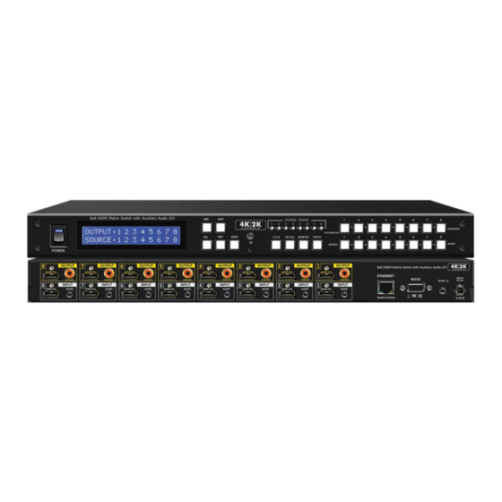
MODEL : HD-MTX-88-4KA
8x8 HDMI Matrix Switch with Auxiliary Audio I/O
INSTRUCTION MANUAL
8x8 HDMI Matrix Routing Switch w/ Full EDID Management/Learning w/ Auxiliary
Audio Input/Output 4k2k Capable
HDMI-AUDIO MATRIX SWITCHER SERIES
Thank you for purchasing the HD-MTX-88-4KA HDMI Matrix Switch with Auxiliary. You will fi nd this unit easy
to install and highly reliable but it is essential that you read this manual thoroughly before attempting to use
8x8 HDMI Matrix switcher.
118 W. Streetsboro Street, Ste. 125 | Hudson, OH 44236 | Toll Free: (866) 865-7737
Advertisement
Table of Contents

Related Manuals for KVMSwitchTech HD-MTX-88-4KA


Summary of Contents for KVMSwitchTech HD-MTX-88-4KA
- Page 1 HDMI-AUDIO MATRIX SWITCHER SERIES Thank you for purchasing the HD-MTX-88-4KA HDMI Matrix Switch with Auxiliary. You will fi nd this unit easy to install and highly reliable but it is essential that you read this manual thoroughly before attempting to use 8x8 HDMI Matrix switcher.
- Page 2 SAFETY INFORMATION To ensure the best results from this product, please read this manual and all other documentation before operating your equipment. Retain all documentation for future reference. Follow all instructions printed on unit chassis for proper operation. To reduce the risk of fi re, do not spill water or other liquids into or on the unit, or operate the unit while standing in liquid. Make sure power outlets conform to the power requirements listed on the back of the unit.
-
Page 3: Table Of Contents
6.75 Gbps. Supports UXGA/WUXGA/DVI 1920x1200 resolution to any HD displays. The HD-MTX-88-4KA has 1x We reserve the right to make improvements to this document and/ HDMI and Auxiliary Audio(analog stereo audio) connector for or product at any time and without notice. -
Page 4: Package Contents
PACKAGE CONTENTS PACKAGE CONTENTS Check that you have the following components; • HD-MTX-88-4KA Matrix Switcher • RS-232 V2.0 Protocol Instructions • Ethernet V2.0 Protocol Instructions • Master wireless IR Remote Control (SW-HD88AK) • 19 inch Ear mount bracket (Part # 1U-440L) •... -
Page 5: Features
FEATURES FEATURES • (8)x HDMI with Auxiliary Audio (Analog Audio) source devices matrix switched to • (8)x HDMI with S/PDIF output destinations • HDMI digital Video w/embedded HDCP, DVI format and CEC/HDCP 2.0 compliant • Worldwide control EDID modes for HDMI full 4K2K (24/30 Hz) HD Video resolutions •... -
Page 6: Specifications
SPECIFICATIONS SPECIFICATIONS • Type of HDMI Switcher: 8x inputs To 8x Outputs HDMI Matrix Switch with Audio and Extension • HDMI Support: HDMI 4K2K, 1080p-@60Hz, H36-bit Deep color, 3D of HDMI V1.4 formats • HDCP / CEC Support: HDCP 2.0 Compliant, CEC Compliant •... -
Page 7: Front Panel
FRONT PANEL FRONT PANEL 1. POWER ON SWITCH The power switch turns the unit on and off. The LCM will illuminate blue to indicate the switcher is ON and receiving power. The switcher will remember the last setting during a power cycle. When power is removed and resorted, the last confi guration will be evoked. 2. -
Page 8: Front Panel- Arc
FRONT PANEL- ARC FRONT PANEL 9. FUNCTION KEY - ARC Audio Return Channel (ARC) is a feature that sends audio from the TV back down the HDMI cable to its source device, in this case, the switcher, Not all displays support ARC; check your Users Guide for additional information. ( Default = ARC Disabled ) The “Audio &... -
Page 9: Front Panel- Aux
FRONT PANEL- AUX FRONT PANEL 10. FUNCTION KEY - AUX (The audio additional on the “Audio / ARC” port ) The AUX FUNCTION feature allows you to replace the embedded HDMI audio signal with an audio signal that is connected to the switchers Audio AUX Input. -
Page 10: Front Panel- Edid
FRONT PANEL- EDID FRONT PANEL 12. FUNCTION KEY - EDID (1) Used to display change current EDID mode. - Press EDID to select new EDID mode or select - Press SOURCE row #1 or #2 Select EDID modes. - Press ENTER to ready memory location. - Or press EDID again to cancel operation. -
Page 11: Front Panel - All - Off - Lock - Enter
FRONT PANEL - ALL - OFF - LOCK - ENTER FRONT PANEL 13. FUNCTION KEY - ALL Disables (mute) video on all destinations OR assign the same source to all destinations. Option 1 - Press ALL followed by OFF button. The display will show ”0” to indicate none of the destinations are assigned a video source. Option 2 - Press ALL followed by Source 1 thru 8. -
Page 12: Front Panel - Recall - Memory
FRONT PANEL - RECALL - MEMORY FRONT PANEL 17. FUNCTION KEY - RECALL The system will show previously stored presets, up to a total of 16. Presets are stored in local memory using Source keys 1 thru 8 or Destination keys 1 thru 8 as the memory preset location. - Press RECALL button. -
Page 13: Rear Panel
BACK PANEL - SWITCH CONTROLS BACK PANEL 1. DC POWER INLET: Power Socket : The Switcher is fi tted with a DC power plug input connector. DC Jack - inner OD Ø 2.1mm (+ ) Ensure that the used is of an approved type and is of suffi cient Outside OD Ø... -
Page 14: Back Panel - Hdmi Input / Output
BACK PANEL - HDMI INPUT / OUTPUT BACK PANEL 5. INPUTS- 1,2,3,4,5,6,7, & 8 HDMI: HDMI Connector: HDMI Type A SMD 19pin Female Connect a HDMI signal source link of HDMI source direct HDMI socket connector. digital video/audio to this Female HDMI connector. This HDMI Note: With the proper adapters, the switcher port support HDMI and DVI digital video sources. -
Page 15: Remote Control
REMOTE CONTROL Before making any connections to the switcher, observe the following: • Ensure the mains voltage supply matches the label on the supplied plug- Pack (+/- 10%). • Ensure that the power switch is OFF. • Ensure that all system grounds (earth) are connected to a common point. •... - Page 16 REMOTE PROTOCOL COMMANDS IR REMOTE CUSTOM AND DATA CODES (NEC STANDARD) HOW TO SETUP IR CODES : CUSTOM CODE : 01FC POWER ON : 01FC A15E POWER OFF : 01FC A25D ARC : 01FC B847 LOCK : 01FC B54A AUX : 01FC 9966 EDID : 01FC B748...
-
Page 17: Edid Functions
EDID FUNCTION EDID FUNCTION FOR HDMI MATRIX SWITCHER EDID Setup To Change the EDID Setup Step 1. Press the EDID button The display will show the currently selected EDID mode Step 2. Press SOURCE #1 or #2 button row The button will fl ash blue and the display will show the current Embedded EDID Status. Step 3. - Page 18 EDID FUNCTION Mode 5 . H36-3D-M (1080p-36 bits) Audio Support : MAT(MLP) 7.1CH, PCM 2CH, One Bit Audio 2CH, AC-3 5.1CH, DTS 5.1CH, PCM 7.1CH, Dolby Digital + 7.1CH, DTS-HD 7.1CH Mode 6 . 4K2K (24/30Hz) HDMI Support : 4K2K-3D, PCM 2CH (3860x2160-24/30Hz) Audio Support: PCM 2CH Mode 7 .
- Page 19 EDID FUNCTION Learning EDID Single to Single Example : Learn Destination #8 EDID To Source #5. The button will fl ash blue and the display will show the current Embedded EDID Step 1. Press EDID button Status. Step 2. Press the Destination #8 button row Copy the Destination #8 Display EDID.
-
Page 20: Typical Application
INSTALLING DIAGRAM Samples connection : 1. Using IR External, RS-232 or Ethernet command to control Switcher HD-MTX-88-4KA via PC or SB-100 IR receiver transmit the HD- MTX-88-4KA’s IR signal. 2. Audio output link ARC from TV return channel, HDMI audio source or mixing Auxiliary audio. -
Page 21: Ir Extender
IR EXTENDER REAR PANEL IR EXTENDER PORT Note: When you plug the External IR extender into the switcher, the front panel IR receiver Note: remains active. IR EXTENDER PACKAGE : HOW TO SETUP THE IR EXTENDER RECEIVER COMPONENTS Pin confi guration for IR 984 feet (300 meters) Extender Receiver such as SB-100 compatible Pin confi... -
Page 22: Ethernet Serial Interface
ETHERNET SERIAL INTERFACE ETHERNET SERIAL INTERFACE CONNECT A PC OR CONTROL SYSTEM VERSION COMPATIBLE V2.0 For a complete list of commands, please reference external document extended Ethernet Protocol Instruction Manual. ETHERNET SERIAL INTERFACE Pin Ethernet Reference TXOP TX + TXON TX - RXIP RX +... -
Page 23: Rs-232 Protocol
RS-232 SERIAL INTERFACE RS-232 SERIAL INTERFACE CONNECT A PC OR CONTROL SYSTEM. VERSION -2.0 COMPATIBLE For a complete list of commands, please reference external document extended RS-232 Protocol Instruction Manual. RS-232 SERIAL INTERFACE RS-232 Defi nition -------- Not used Transmitter Receiver -------- Not used... - Page 24 TERMS AND CONDITIONS OF USE PLEASE READ THE FOLLOWING TERMS AND CONDITIONS CAREFULLY BEFORE USING THIS HARDWARE, COMPONENTS AND SOFTWARE PROVIDED BY, THROUGH OR UNDER KVM Switch Tech, INC (COLLECTIVELY, THE “PRODUCT”). By using installing or using the Product, you unconditionally signify your agreement to these Terms and Conditions.
Need help?
Do you have a question about the HD-MTX-88-4KA and is the answer not in the manual?
Questions and answers