Table of Contents
Advertisement
Quick Links
Advertisement
Table of Contents

Subscribe to Our Youtube Channel
Related Manuals for Ateis PRIMA-VA/R


Summary of Contents for Ateis PRIMA-VA/R
- Page 1 PRIMA-VA/R Stand-Alone Voice Alarm System Controller with DSP & integrated 6 Class-D amplifiers User Manual Version V3.01 www.ateis-europe.com © 2020 ATEÏS Europe B.V. – Celsiusstraat 1 – 2652 XN Lansingerland – Netherlands Phone: +31 (0)10 208 8690 – @: info@ateis-europe.com...
-
Page 2: Table Of Contents
Pages Table of Contents Welcome ................................... 4 1 Introduction .................................. 5 2 CE – EN Certification ..............................6 3 Safety declaration ................................. 7 4 How to connect PRIMA VA ............................9 4.1 Wiring diagram ................................9 4.2 Technical characteristics ............................10 §... - Page 3 7.3 How to configure automatic volume control on outputs ..................60 7.4 How to send audio signal to third party equipment over network ................ 61 7.5 How to receive audio signal from third party equipment over network ..............62 7.6 How to configure network options and functionalities ..................63 7.7 How to configure SIP user accounts ........................
-
Page 4: Welcome
Please read the present PRIMA VA User Manual carefully before installing your PRIMA VA. It contains useful information and helps you getting started quickly. Visit our web site www.ateis-europe.com for more information on ATEÏS products and services. Thank you for purchasing ATEÏS products. -
Page 5: Introduction
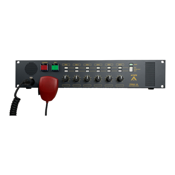
Introduction PRIMA-VA/R is a compact PAVA controller that offers 6 monitored speaker zones or 5 monitored speaker zones with back-up amplifier. This controller is integrated with 6 high efficiency Class-D amplifiers built- in and is capable of handling 80 Watts speaker load per zone which provides ease of system wiring and installation. -
Page 6: Ce - En Certification
CE – EN Certification © 2020 ATEÏS Europe B.V. S.A.S... -
Page 7: Safety Declaration
Safety declaration • Do not expose the unit to extreme temperatures, direct sunlight, humidity or dust, which could cause fire or electrical shock hazard. • Keep away water or other liquids from the device. Otherwise fire or electrical shock may result. •... - Page 8 • Leave enough space above and below the unit to provide good ventilation. If airflow is not adequate, unit will heat up and fire hazard may result. • Operate the unit in an environment with a free-air temperature between 0°C and 40°C (32°F and 104°F).
-
Page 9: How To Connect Prima Va
How to connect PRIMA VA Wiring diagram © 2020 ATEÏS Europe B.V. -
Page 10: Technical Characteristics
Technical characteristics § Mains power supply Voltage range 115 – 230 VAC (50 – 60 Hz) Max consumption 1.7 A by 230 VAC Standby consumption 0,32 A by 230 VAC Cable specification 3 x 0.75 mm² EU cord § Backup power supply Voltage range 21.6 to 28.8 VDC Max consumption... -
Page 11: Db Output
Signal to noise ratio (SNR) 87 dB Total harmonic distortion < 0.2 % (THD) Cable specification 2 x 1.5 mm² fire retardant cable 0 dB output § Balanced output + Hot - Cold G Ground Maximum level +8 dBu (1.4 Bandwidth 20 ~ 20K Hz Signal to noise ratio (SNR) -
Page 12: How To Configure Prima Va - Global Settings
How to configure PRIMA VA – Global settings How to connect your PC to PRIMA VA PRIMA VA is based on an embedded HTTP server. Factory default IP address is 192.168.10.159. By entering this factory default IP address on a browser like Firefox or Chrome, you will connect PRIMA VA to your PC and following Home page will be displayed. - Page 13 System menu should be used to set global parameters, such as network settings, firmware update, password change, time settings and log file. Basic config and Advanced config should be used to configure PRIMA VA according to application requests, on 2 different levels. Basic config should be used to set up front panel, audio inputs and outputs, logic inputs and outputs, monitoring, events, scheduler settings and configuration file import and export.
- Page 14 2 different access levels are available, according to EN54-16 regulation (levels 3 and 4). Factory default ID to modify configuration (level 3) is following: § Login config § Password ateis Factory default ID to change login and password and to upload firmware (level 4) is following: § Login firmware § Password ateis It is possible to change login and password on restricted access.
-
Page 15: How To Modify Network Settings
How to modify network settings § Click on System > Network. PRIMA VA is working only with fixed IP address. § Modify writable parameters like Host name, IP address, Network mask or Gateway. § Click on Apply changes to save modifications. ©... -
Page 16: How To Update Firmware
How to update firmware § Click on System > Firmware. Level 4 access is requested to open this page. This page allows you to check current version and to update PRIMA VA with new firmware version. File format is following: BFModule X.Y.Z.ldr for boot loader PrimaVA X.Y.Z.ldr for firmware with X, Y and Z are depending on version. - Page 17 All items should be validated with a green check. Otherwise boot loader or firmware file is not compatible with PRIMA VA unit. § If all items have been validated with a green check, click on Flash new firmware to upload new file. Following page should appear and be displayed as long as programming process is running: ©...
-
Page 18: How To Change Login And Password
How to change login and password § Click on System > Password. Level 4 access is requested to open this page. Login and password can be changed on this page. § Click on Apply changes to save modifications. © 2020 ATEÏS Europe B.V. -
Page 19: How To Set Date And Time
How to set date and time There are 2 options to set date and time, either manually from System > Time page, as described in this section, or automatically by receiving date and time from an NTP server. This second option is only working if PRIMA VA is connecting to Internet. - Page 20 To copy date and time from PC: § Click on Apply current time to save modifications. 5.5.2. How to set date and time automatically § Click on Advanced config > Network. § Enter IP address of an NTP server. § Click on Apply changes to save modifications.
-
Page 21: How To Read And Download Logfile
How to read and download logfile § Click on System > Log. § Click on Read to read log file. § Click on Download to save log file on PC (text file). § Click on Reset to delete all events on log file. ©... -
Page 22: How To Configure Prima Va - Basic Configuration
How to configure PRIMA VA – Basic configuration How to upload and download configuration file § Click on Basic config > Import/Export. Default file name is config.PrimaVA. To download configuration file on PC: § Click on Export current configuration to download configuration from PRIMA VA to PC. To upload configuration file from PC: §... -
Page 23: How To Upload Audio Files And Configure Messages
How to upload audio files and configure messages Click on Basic config > Messages. § 6.2.1. How to upload audio files First step is to store audio files into flash memory. File format is name.wav or name.mp3. PRIMA VA audio files storage capacity is displayed on this page. Parameter Access Description... - Page 24 If all audio files have to be deleted: § Click on Delete all files. 6.2.2. How to configure messages Second step is to configure messages, using pre-stored audio files. Up to 100 messages can be configured on PRIMA VA. Each message is referenced by its number, between 1 and 100, as defined in Select message scroll list.
- Page 25 Parameter Access Description Name Read / Write Name of the message as it appears in the scroll list Priority of the message – Lowest priority = 0 – Highest priority = Priority Read / Write Gain Read / Write Audio level of the message Global repeat Read / Write Repetition index of the sequence, as long as trigger is active...
- Page 26 To erase all messages: Click on Erase all messages . § © 2020 ATEÏS Europe B.V.
-
Page 27: How To Configure Front Panel
How to configure front panel § Click on Basic config > Front panel. Parameter Access Description Message which is triggered by pressing front panel Select message Read / Write EVACUATION button Line 1 Read / Write 100V loudspeaker line 1 Line 2 Read / Write 100V loudspeaker line 2... - Page 28 Front panel page allows to configure Fireman microphone and Evacuation button. Front panel Reset button has been designed to: § Stop message triggered by Evacuation button (if Stop Message option checked) § Silence buzzer in case of fault § Check visual and acoustic indicators – Refer to How to check visual and acoustic indicators section To trigger evacuation message from Evacuation button: §...
-
Page 29: How To Configure Audio Inputs And Outputs
How to configure audio inputs and outputs § Click on Basic config > Audio. Regarding audio inputs, 2 balanced analog audio inputs, 2 call stations (microphones), a front microphone and 4 audio streams are available on PRIMA VA. User decoders 1 to 4 allow to receive 4 simultaneous audio streams from network. Regarding audio outputs, 6 loudspeaker lines, 1 balanced 0vdB output and 2 call stations (loudspeakers) are available on PRIMA VA. - Page 30 6.4.1. To configure analog audio inputs Click on Audio Input 1 Audio Input 2. § AGC Max Gain and AGC Target Level are displayed only if Auto Gain Control option is selected. Static Gain is displayed only if Auto Gain Control option is not selected. Activity Threshold and Activity Hold Time are displayed only if Activity Detection Events option is selected.
- Page 31 Activity Hold Time Read / Write Time before audio input release if no modulation detection Monitored Read / Write Pilot ton detection – Fault report if no pilot ton detection Monitoring Threshold Read / Write Pilot ton level to be detected Monitoring Time-out Read / Write Time before fault report if no pilot tone detection...
- Page 32 Static Gain Read / Write Front microphone gain adjustment Front microphone priority – Lowest priority = 0 – Highest priority = Priority Read / Write Contact and microphone capsule monitoring – Fault report for Monitored Read / Write contact and microphone capsule Front microphone is allowed to page even if mains power supply Security Read / Write...
- Page 33 6.4.4. To configure user decoders § Click on User Decoder 1 User Decoder 2 User Decoder 3 User Decoder 4. Activity Threshold and Activity Hold Time are displayed only if Activity Detection Events option is selected. Monitoring Threshold and Monitoring Time-out are displayed only if Monitored option is selected. Parameter Access Description...
- Page 34 6.4.5. To configure loudspeaker lines § Click on Line 1 Line 2 Line 3 Line 4 Line 5 Line 6. Parameter Access Description Output absolute level for all inputs which are defined as Evacuation Evacuation level Read / Write inputs Output relative level for all paging inputs which are not defined as Paging gain Read / Write...
- Page 35 Level and Frequency are displayed only if Pilot tone option is not set on OFF. Parameter Access Description Output absolute level for all inputs which are defined as Evacuation Evacuation level Read / Write inputs Output relative level for all paging inputs which are not defined as Paging gain Read / Write Evacuation...
- Page 36 Paging sources are played on 0dB output (depending on source and Paging Read / Write minimum priority) Music sources are played on 0dB output (depending on source and Music Read / Write minimum priority) Minimum priority Read / Write Sources with priority equal or higher are played on 0dB output §...
- Page 37 6.4.8. To configure front speaker Front speaker is used as buzzer to signalize faults and as a loudspeaker to listen selected source types (evacuation, paging and music), according to source priority: Automatic listening functionality. Highest priority routed source is played on front speaker, according to selected source types and minimum priority value.
- Page 38 6.4.9. To configure master audio levels: Normal Preset, Night Preset, Attenuated Preset and Loud Preset are moved to Master level, according variable values, to control level on all outputs (loudspeaker lines 1 normal, night, attenuated loud to 6, 0 dB output). Evacuation signal are not affected by all group gains.
- Page 39 Master relative gain for all analog audio inputs (gain set on page Inputs Gain Read / Write Audio Input is relative to this gain) Master relative gain for all messages (gain set on page Messages is Messages Gain Read / Write relative to this gain) Master relative gain for all IP streams (gain set on page User Decoder IP Streams Gain...
-
Page 40: How To Configure Logic Inputs And Outputs
How to configure logic inputs and outputs This section explains how to setup logic, analog and selector inputs. Please to Basic config > Events section to learn how to assign commands to these input states (ON, OFF, knob value, selector position). §... - Page 41 6 knobs are available on PRIMA VA front panel. These knobs can be configured as analog or selector inputs. 2 opto-isolated voltage inputs are available on PRIMA VA rear panel. These voltage inputs can be configured as logic inputs only. A 24VDC voltage has to be connected to trigger these inputs. 6.5.1.
- Page 42 6.5.2. To configure front knobs § Click on Front Knob 1 Front knob … 6.5.2.1. Front knob defined as analog input Parameter Access Description Mode Read / Write Logical (ON / OFF) or Analog or Selector Value for minimum Read / Write Minimum scaler value if knob is turned on minimum position position Value for maximum...
- Page 43 Parameter Access Description Mode Read / Write Logical (ON / OFF) or Analog or Selector Number of positions Read / Write Number of positions defined for the selector Position X Read / Write Click on Calibrate after turning knob on corresponding position §...
- Page 44 6.5.4. To configure relay outputs Relay outputs are activated by variables. Refer to Advanced config > Variables section to learn more about variables. Output is activated if assigned variable is set to 1. Output is deactivated if assigned variable is set to 0. Following variables can activate and deactivate relay outputs.
- Page 45 Modan interface connection modanconn Vox@Net client connection vnclient Vox@Net client 1 active vnactive Vox@Net client 2 active Vnactive2 Vox@Net system fault vnfault Vox@Net global evacuation vngloevac AC mains presence mains AC/DC mains power supply 24V DC power supply Power supply fuses fuses All amplifiers / lines global status ampline...
-
Page 46: How To Configure Events
How to configure events Command scripts are assigned to a variable event and are executed when event is detected on variable. Example: Assigned command scripts on remin1on variable event are executed when logic input 1 is activated. Events list is predefined for built-in variables, according to variable type. It is also possible to create user defined events, linked to user defined variables. - Page 47 – Basic config > Messages) is routed on zones 1 to 6 dst=1,2,3,4,5,6 ) and 0 dB output ( dst=7 Refer to ATEIS VNB command framework document to get command syntax. Click on Apply changes to save modifications. § §...
-
Page 48: How To Configure Call Stations
How to configure PSS-G2 call stations § Click on Basic config > Call station 1 or Call station 2. § Select PSS-G2 in Mode list. Up to 1 chime and 4 audio messages can be assigned to a PSS-G2 call station. Lock delay is displayed only if Access Code is set. - Page 49 Delay to re-enter code to access call station (not applicable if no Lock delay Read / Write access code configured) Delay to shutdown screen backlight, if any button pressed during Backlight delay Read / Write this time § Click on Apply changes to save modifications. §...
-
Page 50: How To Configure Scheduler
How to configure scheduler § Click on Basic config > Scheduler. This page shows all created programs and allows to create new programs, to set program parameters, to assign commands, to delete program and to enable / disable program. To create a new program: Enter a program name (Program ID) and a program description (Description) §... - Page 51 Parameter Access Description Description Read / Write Program description Assign commands to program are executed only if program is Enabled Read / Write enabled Mode Read / Write Triggered by command or Daily or Yearly or Daily and yearly Start Date Read / Write First date program is triggered Stop Date / Never...
- Page 52 ) and 0 dB output ( dst=1,2,3,4,5, 6 dst=7 Refer to ATEIS VNB command framework document to get command syntax. § Click on Apply changes to save modifications. Click on Clear actions to delete all assigned commands on editor.
-
Page 53: How To Monitor Amplifiers And Loudspeaker Lines
How to monitor amplifiers and loudspeaker lines § Click on Basic config > Monitoring. Amplifier monitoring is based on voltage ratio between amplifier signal input and output, measured on pilot tone signal. Loudspeaker line monitoring is based on impedance measurement, measured on pilot tone signal. Pilot tone frequency can be set to 20 or 22k Hz. - Page 54 Impedance @ 1k Hz Read only Loudspeaker line impedance reference by 1k Hz pilot tone Impedance @ 20k Hz Read only Loudspeaker line impedance reference by 20k Hz pilot tone Impedance @ 22k Hz Read only Loudspeaker line impedance reference by 22k Hz pilot tone §...
-
Page 55: How To Configure Prima Va - Advanced Configuration
How to configure PRIMA VA – Advanced configuration How to use user defined variables User defined variables can be used on different applications, one of them is selection of music streams according to the position of an external selector (logic input configured as X positions selector – Refer to Basic config >... - Page 56 Parameter Access Description Read only Variable name Type Read only Boolean, Integer or String Description Read / Write Variable description Current value Read / Write Current value by opening variable edit page Set variable to default value or save variable current value in Reset value Read / Write configuration file...
- Page 57 event is corresponding to logic input 5 in position 1. remin5is1 If logic input 5 is on position 1, multicast stream 239.240.1.1 is assigned to musicstream variable. If logic input 5 is on position 2, multicast stream 239.240.1.2 is assigned to variable.
-
Page 58: How To Use Defined Commands
How to use defined commands User defined commands can be used to execute a script including several actions (for example, playing a message on different zones and activating a logic output simultaneously). Commands are very useful if PRIMA VA is controlled by third party equipment. Example: A third party equipment triggers a message stored on PRIMA VA. - Page 59 Third party equipment has the possibility to choose which message should be played. A new parameter should be created and assigned to command. To create a new parameter: § Enter a parameter name. § Select a variable type (Boolean, integer, string, IP address). §...
-
Page 60: How To Configure Automatic Volume Control On Outputs
How to configure automatic volume control on outputs Each output level can be controlled automatically according to noise level measurement. An ATEÏS NSM or another sensing microphone can be connected on PRIMA VA audio input 1 or 2 to measure noise level in controlled zone. -
Page 61: How To Send Audio Signal To Third Party Equipment Over Network
How to send audio signal to third party equipment over network PRIMA VA is able to encode simultaneously 2 audio signals. Purpose of encoders is to transmit local analog audio input signals to third party equipment over network. Encoder 1 is automatically assigned to analog audio input 1, encoder 2 to analog audio input 2. §... -
Page 62: How To Receive Audio Signal From Third Party Equipment Over Network
How to receive audio signal from third party equipment over network PRIMA VA is able to decode simultaneously 4 audio signals. Purpose of decoders is to receive encoded audio streams from third party equipment over network. Decoders 5 to 8 are not accessible for users. These decoders are automatically assigned by PRIMA VA audio engine to dynamic streams like messages or Vox@Net channels. -
Page 63: How To Configure Network Options And Functionalities
How to configure network options and functionalities PRIMA VA is a standalone system, that means it can be used without any network communication. But it is possible to connect PRIMA VA to a network in case product should be able to send and receive to/from third party equipment. -
Page 64: How To Configure Sip User Accounts
How to configure SIP user accounts § Click on Advanced config > SIP. To create a new SIP user account: § Enter a user account and a account name. § Click on Create a new account . New account appears now in SIP user accounts list. To set SIP user account parameters: §... - Page 65 Target port and Target address are displayed only if Send audio mix stream option is selected. © 2020 ATEÏS Europe B.V.
- Page 66 Parameter Access Description User name Read / Write SIP account Display name Read / Write Displayed name for user Registration server Read / Write SIP server IP address New password Read / Write SIP server password Confirm password Read / Write SIP server password confirmation Priority Read / Write...
-
Page 67: How To Use Prima Va
How to use PRIMA VA How to silence buzzer Buzzer is automatically triggered in case of new fault. To silence buzzer, press front panel RESET button during 1 second. How to test indicators All front panel LEDs, buzzer and status outputs Evacuation and Fault can be tested. To test all indicators, press front panel RESET button during 3 seconds. -
Page 68: Troubleshooting
Troubleshooting This section provides a list of faults which can be displayed on Basic status / State page, including tips to fix issues. § Network Fault message Fault description No access to network Variable: ethlink Fault activation: Ethernet link Fault if link down (Advanced config > Network page) Points to check: PRIMA VA is connected to network (RJ45 cable) IP settings (IP address, network mask, gateway) are correct... -
Page 69: Logic Inputs
§ Logic inputs Fault message Fault description Fireman microphone activation button is faulty (open or short-circuit) Variable: micconn Front microphone connection Fault activation: Monitored (Basic config > Audio > Front microphone page) Points to check: PRIMA VA front microphone is connected to front panel XLR plug Logic input X value is considered as faulty (open or short-circuit) Variable: reminXstate... -
Page 70: Amplifiers
Points to check: Audio signal is sent from third party equipment Monitoring threshold and time-out are correctly set § Amplifiers Fault message Fault description Amplifier X gain is lower than 10% of reference gain value Variable: amplineX Amplifier X down Fault activation: Monitored (Basic config >... -
Page 71: Third Party Communication
§ Third party communication Fault message Fault description No communication with third party equipment connected on TCP protocol Variable: cmdconn Fault activation: Command interface connection Fault if not connected (Advanced config > Command interface page) Points to check: PRIMA VA is connected to network (RJ45 cable) Interface settings (IP port) are correct No communication with third party equipment connected on MODAN protocol... -
Page 72: System Faults
Not configurable Points to check: Contact your ATEÏS dealer for support PSS-G2 microphone output signal is not detected on PRIMA VA Variable: csXmicout Fault activation: PSS-G2 microphone output Not configurable Points to check: Check all RJ45 wires on PSS-G2 connection are correctly connected Contact your ATEÏS dealer for support PSS-G2 LCD (screen) is faulty Variable:... - Page 73 Import configuration file (Basic config > Import/Export page) Contact your ATEÏS dealer for support if configuration import not successful Configuration wrong product Configuration file is not corresponding to PRIMA VA configuration Variable: configuration Fault activation: Not configurable Points to check: Import PRIMA VA (*.PrimaVA) configuration file (Basic config >...
- Page 74 Fault activation: Not configurable Points to check: Contact your ATEÏS dealer for support LED Driver LED Driver is faulty or not accessible Variable: leddriver Fault activation: Not configurable Points to check: Contact your ATEÏS dealer for support © 2020 ATEÏS Europe B.V.
-
Page 75: Contact Information
Avenue des Baumettes 9, Celsiusstraat 1 - 2652 XN Lansingerland (Rotterdam Region), Netherlands 1020 Renens VD, Switzerland Tel: +31 (0) 10 2088690 Tel: +41 (0) 21 881 25 10 info@ateis-europe.com info@ateis.ch ATEÏS France S.A.S ATEÏS SE Europe France Southeast Europe...
Need help?
Do you have a question about the PRIMA-VA/R and is the answer not in the manual?
Questions and answers