Table of Contents
Advertisement
Quick Links
Loewe Service
Europa
Europe
•
Benelux
Italien
Loewe Opta Benelux NV / SA
General Trading Trust SpA
Luitenant Lippenslaan 54 B
Via Volturno 10/12 - Scala B
B-2140 Antwerpen
I - 50019 Sesto Fiorentino (Fl)
Tel. 0902 - 88002
Tel. 055 - 300342
Fax 03 - 2354837
Fax 055 - 300343
Loewe Opta Nederland B.V.
Malta
Ravenswade 54A1
Mirage Holdings LTD
NL - 3439 LD Nieuwegein (Utrecht)
Flamingo Complex
Tel. 0900 - 2020180
Cannon Road
Fax 030 - 2803327
M - Qormi
Tel. 497182
Dänemark
Fax 445983
Semi-Tech ConsumerElectronics (Denmark)
A/S
Norwegen
Hørskætten 3
CableCom AS
DK - 2630 Taastrup
Bekkevn, 9
Tel. 43597777
N - 3218 Sandefjord
Fax 43597700
Tel. 033 / 483348
Fax 033 / 483333
Deutschland
LOEWE OPTA GmbH
Österreich
Service und Logistik / Zentrale Kronach
Rovert Bosch AG
96305 Kronach • Postfach 1554
Postfach 146
96317 Kronach • Industriestrasse 11
A - 1011 Wien
Tel. 0180 - 5221800
Tel. 01 - 797224500
Fax 0180 - 5221806
Fax 01 - 797224599
DxJ-Tin.-Nr. 0926199
Pirngruber
Internet: http.//www.loewe.de
Elektronik Service & Vertriebsges. m.b.H
Frankreich
Dauphinestr. 226
Sorep Import S.A. Loewe Opta
A - 4030 Linz
11 Rue de la Durance
Tel. 0732 / 387282-0
BP 954
Fax 0732 / 387282-20
F - 67029 Strasbourg Cédex 1
Polen
Tel. 3 - 88797250
PPHU PAROS Sp. zo.o.
Fax 3 88797259
ul. Ustronie 1-3
Griechenland
PL - 50-302 Wroclaw
SOUND HELLAS S.A.
Tel. 071 - 3222014, 3222017
Kleanthous Str. 10
Fax 071 - 3221061
GR - 54642 Thessaloniki
Portugal
Tel. 0030 - 31 - 856100
Videoacustica
Fax 0030 - 31 - 856300
Comercio e Representacoes de
Grossbritannien
Equipamentos Electronicos S.A.
Linn Products Limited
Estrada Circunvalacao
PO Box 8465
Apartado 3127
Pestwick
P - 1301-902 Lisboa Codex
UK - KA 7 2YF
Tel. 01-4170004
Tel. 0044 - 1292471552
Fax 01-4188093
Fax 0044 - 1292471554
GUS
Service Center Loewe
ul. Verkhnyaya Maslovka, d. 29
RUS - 125083 Moscow
Tel. 095 - 2125043, 9566764
Fax 095 - 2124710
Loewe Service
Übersee
Overseas
•
Australien
lsrael
International Dynamics
RIF LTD
(Wholesale)PTY LTD
29, lzhak Sade Street
78-80 Herald Street
IRS - Tel Aviv 67213
AUS-Cheltenham, Victoria 3192
Tel. 03 - 6240555
Tel. 03 - 95850522
Fax 03 - 6240303
Fax 03 - 95850179
Reservado el derecho a introducir modificaciones
8-20-2007
Schweden
Elektronikservice i GBG AB
Fridkullagatan 23
S - 41262 Göteborg
Tel. 031 - 811486
Fax 031 - 812770
Schweiz
Telion AG
Rütistrasse 26
CH - 8952 Schlieren
Tel. 01 - 7321511
Fax 01 - 7301502
Slowenien
Jadran Export Import D.D.
Partizanska cesta 69
SL - 6210 Sezana
ˇ
Tel. 067 - 391402, 391406
Fax 067 - 391400
Spanien & Kanarische Inseln
Gaplasa S.A.
Conde de Torroja, 25
E - 28022 Madrid
Tel. 01 - 7482960
Fax 01 - 3291675
Tschechische Republik
Tipa Spol. SR. O.
ˇ
Dolní námestí 9
CZ - 74601 Opava
Tel. 0653 - 624404
Fax 0653 - 623147
Ungarn
Annex
Kereskedelmi Részvénytársaság
H - 1119 Budapest, Féhérvári út. 44
Tel. 01 - 2066000
Fax 01 - 3826040
Zypern
Pangratis Liveras & Son LTD
Liveras Building
7 Ajax Street
Saint Omologite
CY-Nicosia
Tel. 02-663496
Fax 02-664212, 667936
Ver. Arabische Emirate
USA
Super Trading Establishment
SENSORY SCIENCE CORP.
P. O. Box 46409
7835 East McClain Drive,
Abu Dhabi, United Arab Emirates
Scottsdale,
Tel. 02 - 748787
Arizona
Fax 02 - 741156
USA 85260-1732
Tel. 602 - 9983400
Fax 602 - 9514404
Änderungen vorbehalten
Subject to modification
Modification réserves
Con riserva di modifiche
Wijzigingen voorbehouden
Serviceanleitung
Allgemeine Beschreibungen
Abgleichanleitungen
Blockdiagramme / Schaltbilder
Explosionsansichten / Stücklisten
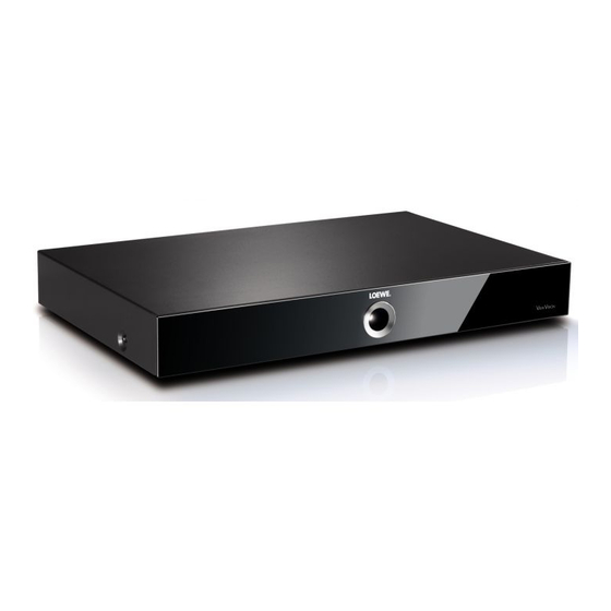
DVB-T/HDD/DVD RECORDER
LOEWE
MODEL
VIEWVISION DR+ DVB-T
Art.-Nr.59515
Advertisement
Table of Contents
Troubleshooting

Related Manuals for Loewe VIEWVISION DR Plus DVB-T


Summary of Contents for Loewe VIEWVISION DR Plus DVB-T
- Page 1 Loewe Service Europa Europe • Benelux Italien Schweden Loewe Opta Benelux NV / SA General Trading Trust SpA Elektronikservice i GBG AB Luitenant Lippenslaan 54 B Via Volturno 10/12 - Scala B Fridkullagatan 23 B-2140 Antwerpen I - 50019 Sesto Fiorentino (Fl) S - 41262 Göteborg...
- Page 2 CONTENTS SECTION 1..SUMMARY SECTION 2..CABINET & MAIN CHASSIS SECTION 3..ELECTRICAL SECTION 4..RS-02A LOADER PART SECTION 5..REPLACEMENT PARTS LIST...
-
Page 3: Table Of Contents
SECTION 1 SUMMARY CONTENTS NEW FUNCTIONS OF DVB-T/HDD/DVD RECORDER ..............1-3 PRODUCT SAFETY SERVICING GUIDELINES FOR DVB-T/HDD/DVD RECORDER PRODUCTS ..................1-4 SERVICING PRECAUTIONS ........................1-5 • GENERAL SERVICING PRECAUTIONS • INSULATION CHECKING PRODEDURE • ELECTROSTATICALLY SENSITIVE (ES) DEVICES SERVICE INFORMATION FOR EEPROM IC SETTING ..............1-6 SPECIFICATIONS ............................1-7... -
Page 4: New Functions Of Dvb-T/Hdd/Dvd Recorder
NEW FUNCTIONS OF DVB-T/HDD/DVD RECORDER • HDMI HDMI IS THE SPECIFICATION FOR THE HIGH-DEFINITION MULTIMEDIA INTERFACE. HDMI IS PROVIDED FOR TRANSMITTING DIGITAL TELEVISION AUDIOVISUAL SIGALS FROM HDD-DVD RECODER TO TELEVISION SETS, OTHER VIDEO DISPLAYS. HDMI CAN CARRY HIGH QUALITY MULTI-CHANNEL AUDIO DATA AND CAN CARRY ALL STANDARD AND HIGH DEFINITION CONSUMER ELECTRONICS VIDEO FORMATS. -
Page 5: Product Safety Servicing Guidelines For Dvb-T/Hdd/Dvd Recorder Products
When servicing this product, under no circumstances should the original design be modified or altered without permission from LOEWE. All components should be replaced only with types identical to those in the original circuit and their physical location, wiring and lead dress must conform to original layout upon completion of repairs. -
Page 6: Servicing Precautions
SERVICING PRECAUTIONS CAUTION: Before servicing the DVB-T/HDD/DVD RECORDER Electrostatically Sensitive (ES) Devices covered by this service data and its supplements and Some semiconductor (solid state) devices can be damaged addends, read and follow the SAFETY PRECAUTIONS. easily by static electricity. Such components commonly are NOTE: if unforeseen circumstances create conflict between called Electrostatically Sensitive (ES) Devices. -
Page 7: Service Information For Eeprom Ic Setting
SERVICE INFORMATION FOR EEPROM IC SETTING 1. Press the END button on the remocon together with button on the front panel about 6 sec. The picture on OSD will be as bellow : Model : VIEWVISION DR+ DVB-T OP1 : DA 11011010 OP2 : 71 01110001... -
Page 8: Specifications
SPECIFICATIONS • GENERAL Power requirements AC 200 ~ 240V, 50/60Hz Power consumption Dimensions (approx.) 430 X 60 X 280mm (w x h x d) without foot Net weight (approx.) 4.6kg Operating temperature 5°C to 35°C Operating humidity 5% to 90% Television system Analog: PAL I, B/G, I/I, SECAM D/K, K1, SECAM L color system Digital: DVB-T standard compliant... - Page 9 SECTION 2 CABINET & MAIN CHASSIS CONTENTS EXPLODED VIEWS .............................2-2 1. CABINET AND MAIN FRAME SECTION ....................2-2 2. DECK MECHANISM SECTION (RS-02A)....................2-3 3. PACKING ACCESSORY SECTION......................2-4...
-
Page 10: Exploded Views
EXPLODED VIEWS 1. CABINET AND MAIN FRAME SECTION SVC purchase order caution Key board is array coming timer board. Purchase order board separately supply incomprehensible. Supply is possible in Location No A50 state in exploded views. -
Page 11: Deck Mechanism Section (Rs-02A)
2. DECK MECHANISM SECTION (RS-02A) RS-02A(DR-10H) -
Page 12: Packing Accessory Section
3. PACKING ACCESSORY SECTION 810 Accessory Assembly RCA Plug(Black) 801 Owner's Manual SCART Cable 832 Disc HDMI Cable 808 Battery Packing Packing... - Page 13 SECTION 3 ELECTRICAL CONTENTS ELECTRICAL TROUBLESHOOTING GUIDE 4. VIDEO IN BLOCK DIAGRAM......3-32 ...3-2 5. VIDEO OUT BLOCK DIAGRAM .....3-33 1. POWER SUPPLY ON SMPS BOARD....3-2 6. AUDIO IN BLOCK DIAGRAM......3-34 2. POWER SUPPLY ON MAIN BOARD....3-4 7. AUDIO OUT BLOCK DIAGRAM .....3-35 3.
-
Page 14: Electrical Troubleshooting Guide
ELECTRICAL TROUBLESHOOTING GUIDE 1. POWER SUPPLY ON SMPS BOARD No .5.3VA Is the F101 normal? Replace the F101 (Use the same Fuse) Is the BD101 normal? Replace the BD101 Is the R101 normal? Replace the R101 Is Vcc (13V - 27V) supplied Is the D102 normal? to IC101 Pin 2? Check or Replace the D102... - Page 15 No 12VL Is the 13.5V supplied Check or Replace the D124 to IC155 pin 1? Check the DVD CTL “H” Is the IC155 pin4 “H”? signal from µ-com Check or Replace the IC155 No 5VL Is the 5.5V supplied to Check or Replace the D125 IC156 pin 1? Check the DVD CTL “H”...
-
Page 16: Power Supply On Main Board
2. POWER SUPPLY ON MAIN BOARD No 12VT Check D124 on SMPS Is the Vcc (14V) supplied to board and replace QP07 collector? Is there about 12.5V at Check QP07 and replace QP02 & QP07 base? Check D126 on SMPS Is the Vcc (33V) supplied board and replace to QP01 emiter? - Page 17 No 5VT Is the Vcc (5.3V) Check 5.3VA on SMPS board supplied to QP05 emiter? Is there about 0V Check QP05 and replace QP06 collector? Is there about 5V Check the “TIMER H” at RP14 and 0.7V signal from µ-COM at QP06 base? Check QP06 and replace No 5V...
- Page 18 No 2.5V Check D154 and Is there about 3V ~ 3.8V D127 on SMPS board at the ICP08 Pin 1? Check the “PWR CTL H” Is there about 4V ~ 5V at signal from µ-COM the ICP08 Pin 3? Check the ICP08 and replace No 3.3V Check D127 on SMPS Is there about 3.8V at...
- Page 19 No SW_5.3VA Is the Vcc (5.3V) Check 5.3VA on SMPS board supplied to QP09 emiter? Check the “STANBY H” Is there about 0V at RP24 and RP25? signal from µ-COM Check QP09 and replace No SW_FD(+) Check D121 on SMPS Is the Vcc (FD+) supplied board and replace to QP11 collector?
- Page 20 No 1.8V Is the Vcc (3.3V) Check 3.3V power supply supplied to Pin 3 ICP03? ICP03 defect There is 1,8V at ICP03 Pin 2, 4 No 1.25V Is there about 3.3V at Check 3.3V on Main board the IC400 Pin 2? Check the “PWR CTL H”...
-
Page 21: System Circuit Part
3. SYSTEM CIRCUIT PART “Please wait” displayed continue at power on IC306 Pin 5 : Check IC704 Pin 19 (/HOST-RESET) X1101 : Clock oscillated? Replace X100 (13.5MHz) Check IC200 (Flash memory), IC200 Pin 32 : IC203, IC201 IC100 defect R170, R169 : 4. -
Page 22: When Playing Disc, No Audio Output
5. WHEN PLAYING DISC, NO AUDIO OUTPUT When playing DISC, no Audio output Check IC900 Pin 5, 6, IC900 Pin 14, 15 : 7, 8 : IC100 defect Is there a signal? Pin 3, 4 (Host CLK & DATA) : IC900 Pin 1, 16 Check Check... -
Page 23: Optical/Digital Output
6. NO OPTICAL/DIGITAL OUTPUT R113 : Is there a signal? R824 : R826 : Is there a signal? Is there a signal? L803 : Check JK804 Pin 2 (5V) Is there a signal? Check JK804 & Check JK805 & optic cable connection RCA cable connection 3-11... -
Page 24: Tuner Audio Output
7. NO TUNER AUDIO OUTPUT TU700 Pin 10 (SIF) : Is there a signal? IC901 Pin 106, 107 Is there a signal? Check IC800 Pin 14 (12V) IC800 Pin 40, 41 : Replace IC800 Pin 30 (5, 3V) Pin 31, 32 Is there a signal? (SCL, SDA) : IC901 Pin 98,... -
Page 25: External Audio Input
8. NO EXTERNAL AUDIO INPUT < AV3 > < AV1/AV2> C925, C926 : IC800 pin 2, 3, 5, 6 : Is there a signal? Is there a signal? Check cable connections & input signal. Check IC800 Pin 14 (12V) Replace IC800 Pin 40, 41 : Pin 30 (5, 3V) IC800... -
Page 26: Rgb/Component Video Signal When Play Disc
9. NO RGB/COMPONENT VIDEO SIGNAL WHEN PLAY DISC L108, L109, L110 : Is there a signal? Check IC800 Pin 14 (12V) IC800 Pin 24, 25, 26 : Pin 30 (5, 3V) Is there a signal ? Pin 31, 32 (SCL, SDA) : Check condition RGB_Sel_Out &... -
Page 27: Composite/S-Video Signal When Play Disc
10. NO COMPOSITE/S-VIDEO SIGNAL WHEN PLAY DISC L107, L111, L112 : Is there a signal? IC800 Pin 27, 29, : Is there a signal? (S-VIDEO) Check S-VIDEO cable connection Check IC800 Pin 14 (12V) Pin 30 (5, 3V) Pin 31, 32 (SCL, SDA) : (SCART) IC800 Pin 36, 39, :... -
Page 28: Tv, External Input Video Signal
11. NO TV, EXTERNAL INPUT VIDEO SIGNAL No TV, external input video signal No video When cable Check signal of external connecting tuner input AV3 cable connection & and rear SCART 1, 2 input signal (Front no TV video signal RCA input) (AV1/2) C827, C840, C845 :... -
Page 29: Dv (Ieee1394) Input (Video/Audio) Signal
12. NO DV (IEEE1394) INPUT (VIDEO/AUDIO) SIGNAL Check DV_Jack connection Change to DV-mode. DV-mode switching? using remote control Check power 3.3V IC304 power 3.3V IC304 Pin 37 : “High” Check IC301 reset circuit & X401 (24.576MHz) oscillated ? IC304 pin 15 : “High” Check DV cable Is there a signal? IC304... -
Page 30: Dvb_T Audio/Video Output
13. NO DVB_T AUDIO/VIDEO OUTPUT Check the RF CABLE Insert the RF cable Check Check Q703,Q703 IC700 pin9, pin10 Is there signal? IC700 pin12, pin6 “H” IC704 pin9 Check 5.3V, 1.8V, 3.3V, 5V R705 Replace TU700 Is there signal? Replace IC100 3-18... -
Page 31: Waveforms
WAVEFORMS 1. SYSTEM BLOCK IC100 Frequency=13.5MHz Main Clock Frequency=198MHz DDR RAM Clock 3-19... - Page 32 IC100 12C_SDA 12C_SCL 3-20...
-
Page 33: Video Block (Color Bar Input)
2. VIDEO BLOCK (COLOR BAR INPUT) CVBS_OUT G/Y_OUT C_OUT B/PR_OUT Y_OUT R/PR_OUT 3-21... -
Page 34: Audio Block (1Khz Sinewave Input)
3. AUDIO BLOCK (1kHz SINEWAVE INPUT) AOUT_FSYNC AOUT_SCLK AOUT_D0 AOUT_MCLK 3-22... -
Page 35: Serial Interface Block (Between Main And I/O)
4. SERIAL INTERFACE BLOCK (BETWEEN MAIN AND I/O) SIO_SPI_CLK SIO_SPI_MOSI SIO_SPI_MISO 3-23... -
Page 36: Tuner Block
5. TUNER BLOCK IC901 3-24... -
Page 37: Hdmi Block
6. HDMI BLOCK IC600 576i/576p mode : 27MHz 720p/1080i mode : 74.25MHz VOUT_CLK VOUT_CLK IC600 VOUT_CLK 3-25... -
Page 38: Wiring Connection Diagram
WIRING CONNECTION DIAGRAM 1. WIRING CONNECTION DIAGRAM 1 TUNER 3-26... -
Page 39: Wiring Connection Diagram 2
2. WIRING CONNECTION DIAGRAM 2 3-27... -
Page 40: Wiring Connection Diagram 3
3. WIRING CONNECTION DIAGRAM 3 3-28... -
Page 41: Block Diagrams
BLOCK DIAGRAMS 1. SMPS BLOCK DIAGRAM 3-29... -
Page 42: Main Block Diagram
2. MAIN BLOCK DIAGRAM 3-30... -
Page 43: Power (Mpeg) Block Diagram
3. POWER (MPEG) BLOCK DIAGRAM 3-31... -
Page 44: Video In Block Diagram
4. VIDEO IN BLOCK DIAGRAM EU1_V_IN TU_V_IN TU700 TU700 D2A_CVBS_IN SW_V_IOUT EU2_V_IN F_CVBS_IN B_SCART_IN G_SCART_IN R_SCART_IN 3-32... -
Page 45: Video Out Block Diagram
5. VIDEO OUT BLOCK DIAGRAM 3-33... -
Page 46: Audio In Block Diagram
6. AUDIO IN BLOCK DIAGRAM TU700 TU700 3-34... -
Page 47: Audio Out Block Diagram
7. AUDIO OUT BLOCK DIAGRAM 3-35... -
Page 48: Power I/O Block Diagram
8. POWER I/O BLOCK DIAGRAM 3-36... -
Page 49: Fld Timer Block Diagram
9. FLD TIMER BLOCK DIAGRAM 3-37... -
Page 50: Timer Block Diagram
10. TIMER BLOCK DIAGRAM 3-38... - Page 51 MEMO...
- Page 52 Lange Reihe 38b 51069 Köln 17121 Loitz Tel. 0221/6801585 Tel. 039998/10577 Fax 0221/6801588 Fax 039998/10566 Loewe-Service und Logistik Die wichtigesten Rufnummern der Zentrale Kronach: LOEWE OPTA GmbH The most important phone numbers of the Kronach headquarters Service + Logistik Telefon: Zentrale Kronach...
-
Page 53: Circuit Diagrams
MODIFIED OR ALTERED WITHOUT PERMISSION CUIT USED. THIS WAY, IMPLEMENTATION OF THE 2. Voltages are DC-measured with a digital voltmeter dur- FROM THE LOEWE. ALL COMPONENTS SHOULD BE LATEST SAFETY AND PERFORMANCE IMPROVE- ing Play mode. REPLACED ONLY WITH TYPES IDENTICAL TO MENT CHANGES INTO THE SET IS NOT DELAYED 1. -
Page 54: Power Interface Circuit Diagram
2. POWER INTERFACE CIRCUIT DIAGRAM 3-41 3-42... -
Page 55: Mpeg Circuit Diagram
3. MPEG CIRCUIT DIAGRAM 3-43 3-44... -
Page 56: Flash/Ddr Circuit Diagram
4. FLASH/DDR CIRCUIT DIAGRAM 3-45 3-46... -
Page 57: Reset, 1394 & Jpeg Circuit Diagram
5. RESET, 1394 & JPEG CIRCUIT DIAGRAM 3-47 3-48... -
Page 58: Atapi Circuit Diagram
6. ATAPI CIRCUIT DIAGRAM 3-49 3-50... -
Page 59: Hdmi Circuit Diagram
7. HDMI CIRCUIT DIAGRAM 3-51 3-52... -
Page 60: I/O Μ-Com Circuit Diagram
8. I/O µ-COM CIRCUIT DIAGRAM 3-53 3-54... -
Page 61: Scart/Rca Jack Circuit Diagram
9. SCART/RCA JACK CIRCUIT DIAGRAM 3-55 3-56... -
Page 62: Av Decoder Circuit Diagram
10. AV DECODER CIRCUIT DIAGRAM 3-57 3-58... -
Page 63: Timer Circuit Diagram
11. TIMER CIRCUIT DIAGRAM 3-59 3-60... -
Page 64: Key (Power Button) Circuit Diagram
12. KEY (POWER BUTTON) CIRCUIT DIAGRAM 3-61 3-62... -
Page 65: Circuit Voltage Chart
INFORMATION : 1. Voltage Check using E/S 2. EE Mode : Check with signal C2 CIRCUIT VOLTAGE CHART 3. Playback Mode : Check with DVD TEST DISC KDV-N chapter 2 4. Record Mode: Check with recording signal C2 using DVD -RW Brand : Imation, VR Mode IC100 DMN8673 IC100... - Page 66 INFORMATION : 1. Voltage Check using E/S 2. EE Mode : Check with signal C2 3. Playback Mode : Check with DVD TEST DISC KDV-N chapter 2 4. Record Mode: Check with recording signal C2 using DVD -RW Brand : Imation, VR Mode PIN NAME PIN NAME PIN NAME...
- Page 67 EE MODE PB MODE REC MODE EE MODE PB MODE REC MODE EE MODE PB MODE REC MODE EE MODE PB MODE REC MODE EE MODE PB MODE REC MODE EE MODE PB MODE REC MODE EE MODE PB MODE REC MODE ICP01 KIA78R05F 5.67V 5.6V...
- Page 68 (AL = Aluminum (AL = Aluminum RECORD MODE STAND BY MODE (T = Tantal RECORD MODE STAND BY MODE LOCA. NO. RECORD MODE POWER OFF MODE LOCA. No. LOCA. No. Electrolytic) NEGATIVE (-) POSITIVE (+) NEGATIVE (-) POSITIVE (+) Condensor) NEGATIVE (-) POSITIVE (+) NEGATIVE (-) POSITIVE (+)
-
Page 69: Printed Circuit Diagrams
PRINTED CIRCUIT DIAGRAMS 1. MAIN P.C.BOARD (TOP VIEW) 3-71 3-72... - Page 70 MAIN P.C.BOARD (BOTTOM VIEW) 3-73 3-74...
-
Page 71: Power P.c.board
2. POWER P.C.BOARD (TOP VIEW) (BOTTOM VIEW) 3-75 3-76... -
Page 72: Timer & Key P.c.board
3. TIMER & KEY P.C.BOARD 4. HDD JUNC P.C.BOARD (TOP VIEW) (BOTTOM VIEW) (TOP VIEW) (BOTTOM VIEW) 3-77 3-78... - Page 73 SECTION 4 RS-02A LOADER PART CONTENTS ELECTRICAL TROUBLESHOOTING GUIDE ..................4-2 THE DIFFERENCE OF DVD-R/RW, DVD+R/RW DISCS AND DVD-ROM ......4-15 1. RECORDING LAYER ..........................4-15 2. DISC SPECIFICATION ..........................4-16 3. DISC MATERIALS ..........................4-16 4. ORGANIZATION OF THE INNER DRIVE AREA, OUTER DRIVE AREA, LEAD-IN ZONE AND LEAD-OUT ZONE..........................4-20 HOW TO USE TEST TOOL ........................4-24...
-
Page 74: Electrical Troubleshooting Guide
ELECTRICAL TROUBLESHOOTING GUIDE Reset or power check. Check it after connecting the power cable only on interface cable for NO Reset or Power ON. Are the pin1 of Check the power (5V/12V) short. LPB272+5V, pin4 of LPB272+12V Repair the SMPS Block respectively after the power cable connecting? Does the pin #8... - Page 75 System check. Load tray without inserting disc. Go to “Tray operating is abnormal” Does Tray operate normally? Does Pick-up move to Go to “Sled operating is abnormal” inside or outside? Go to “Focus Actuator Does Pickup lens operating is abnormal” move up/down? Go to “Laser operating is abnormal”...
- Page 76 Tray operating is abnormal. Tray open doesn’t work. • Check the connction of LIC201 pin 66. Is there Tray • Replace the LIC201. control signal input? • Check the communication line between (LIC301 pin22) LIC201. Is there Tray When LPF303 is drive voltage output? Replace the LIC301.
- Page 77 Sled operating is abnormal. Is there Sled control signal output? Replace the LIC201. (LIC201 pin68, Is there Sled drive voltage input? Check the LR316, LR317. (LIC301 pin4, 30) Is there Check the connection of Sled drive voltage Is CTL1 signal “H”? output? (LIC301 pin1, LIC121 pin31.
- Page 78 Spindle operating is abnormal. Is there Replace the LIC201 Spindle control DSP output? (LIC201 pin70) Is there Spindle drive voltage output? Replace the LIC302 (LIC302 pin19, 21, 24) Is there Check the signal pattern Spindle drive voltage output? between LIC302 and LPM301 (LPM301 pin11, 12, 13) Is there spindle motor’s hall signal sensor output?
- Page 79 Focus servo is unstable Is FE signal Check Pickup output normal in focusing Replace the Pick up. Read Power Up/Down? (LIC121 is 1.3~1.7mW? pin25*) Replace the LIC121. Is FDRV signal output normal in focusing Replace the LIC201. Up/Down? (LIC201 pin 62) * LIC121 pin25 is MOUT2(FEP Monitor2).
- Page 80 Track servo is unstable Is TE signal Is PICK UP Check the PICK UP FFC. output normal in focusing (E, F, G, H) output ON and tracking OFF? normal? (LPM101 Replace the PICK UP. (LIC121 pin 24*) pin8, 5, 9, 4) Replace the LIC121.
- Page 81 Recognition fail case 1 : CD-ROM fail Check pick-up Read power Go to “LD CHECK”. was 1.3 ~1.7mW? Does focus servo Go to “Focus servo is unstable”. operate normally? Check pick-up Check the pick-up FFC and LPM101. RF signal LIC121(pin81) Replace the pick-up.
- Page 82 Recognition fail case 2 : DVD Disc Check pick-up read power Go to “LD CHECK”. was 1.1~1.3mW. Check pick-up Replace the Pickup. RF signal LIC121(pin81) RFOUT was 2~2.5V? Is there Replace the LIC121. RF signal at LIC121 pin95(RFP) and pin96 (RFN)? Check again after the replace Replace the LIC201.
- Page 83 In case of writing fail. Normal case Check the media Check disc label. R/RW? Does the disc Remove the dust, fingerprint and if the have any dust, scratch, disc has long width scratch, change it. fingerprint ...? Eject disc. Finalized disc? If DVD R disc,use new DVD R disc.
- Page 84 Writing Part Check Load tray with DVD R/RW disc. Press the “REC” key. Does writing finish without any error? Is the written file Eject tray. read normally? Go to “LD CHECK”. Is the re-written file read normally? Check and replace LIC201, LIC121, LIC101.
- Page 85 LD CHECK (Laser operating is abnormal) Perform 6. Optical power setting parameter check from “How to use Test tool”. Execute “C.Laser power setup” of Is ALPC parameters valid? “How to use test tool” Perform 5. Optical Power Setting Check reference voltage. OFF level W1SET level &...
- Page 86 CD/DVD? Select Mode : CD, Test and perform Select Mode : DVD, Test and perform Test from 4. LD Test of “How to use Test from 4. LD Test of “How to use Test tool” Test tool” Check the input of CD/DVD. Check the input of CD/DVD.
- Page 87 Select Mode : DVD, Test and perform Select Mode : DVD, Test and perform Test from 4. LD Test of “How to use Test from 4. LD Test of “How to use Test tool” Test tool” Check the input of CD/DVD. Check the input of CD/DVD.
-
Page 88: The Difference Of Dvd-R/Rw, Dvd+R/Rw Discs And Dvd-Rom
THE DIFFERENCE OF DVD-R/RW, DVD+R/RW DISCS AND DVD-ROM 1. RECORDING LAYER • DVD-ROM (Read Only Disc) 0.4 um • DVD+R/RW Disc 4-16... -
Page 89: Disc Specification
2. DISC SPECIFICATION 3. DISC MATERIALS 1) DVD-ROM 4-17... - Page 90 2) Recording format using organic dye material (DVD-R / DVD+R) The format that records data through the creation of recorded marks by changing the organic dye material with a laser beam. • Disc structure • Recording principles [ Recording ] Recording is done by changing the organic dye layer and the substrate with a laser.
- Page 91 3) Recording format using phase-change recording material (DVD-RW / DVD+RW) Data is recorded by changing the recording layer from the amorphous status to the crystalline status, and played back by reading the difference of the reflection coefficient. Amorphous: Non-crystalline. • Disc structure •...
- Page 92 To make recordings, it is necessary to modulate the write pulse, which is called “Write Strategy”. There can be many types in Write Strategy. Typically Write Strategy for DVD R has NMP(Non Multi-Pulse) type and MP(Multi-Pulse) type. In NMP type each single mark is created by subsequent separated short pulses.
-
Page 93: Organization Of The Inner Drive Area, Outer Drive Area, Lead-In Zone And Lead-Out Zone
4. ORGANIZATION OF THE INNER DRIVE AREA, OUTER DRIVE AREA, LEAD-IN ZONE AND LEAD-OUT ZONE 1) Layout of DVD-ROM disc 2) Layout of DVD+R disc 4-21... - Page 94 3) Layout of DVD+RW disc 4-22...
- Page 95 4) Layout of DVD-R/RW disc 4-23...
-
Page 96: How To Use Test Tool
HOW TO USE TEST TOOL 1. ALPC MEASUREMENT SYSTEM We need basically several measurement instruments to adjust Optical Power of CD and DVD Disc • ESSENTIAL INSTRUMENT 1) Optical Power meter & Sensor (ADVANTEST, TQ8230/Q82014A) 2) Personal Computer 3) Adjustment Program (Dragon or ALPC) --> being recommended ALPC Program in case of SVC •... -
Page 97: Execute Alpc Program
3. EXECUTE ALPC PROGRAM 1) Execute Dragon_JW3P.exe file. 2) Enter the password. It is “qaz”. When you enter the password, turn off the “Caps lock” in your keyboard. 3) Set up the target device. Press “ATAPI” button on the main dialog of Dragon tool. And find the target device which is GDA-4164L. - Page 98 4) If the target device setting is completed, execute the “Setup Laser Power(Manual)” in the “Alpc/Opc” menu. 4-26...
-
Page 99: Optical Power Setting
4. OPTICAL POWER SETTING <Test for checking DVD LD and CD LD> When you change the Travers ass’y(including pick-up) or loader PCB, you must do the laser power setting to match pick-up and loader PCB. 1) DVD LD power setting •... -
Page 100: Confirm Optical Power Setting Parameter
5. CONFIRM OPTICAL POWER SETTING PARAMETER LD Test result is ok, but Loader performance is bad. 1. Check ALPC parameter value 1) Press button to open “Results Display” dialog. 2) Press button. ALPC Para - We can see optical power setting value. - Write optical Power Setting value to paper. -
Page 101: Attachment. Optical Power Measurement
6. ATTACHMENT. OPTICAL POWER MEASUREMENT Optical Power measurement is to adjust LD power from Pick-up To measure optical power, LD status is on. Other light affects optical power. Avoid other light to measure exact power Generally headlight power is about 50µW, Sun power is about 100mW. Optical Power measurement method 1. -
Page 102: Internal Structure Of The Pick-Up
INTERNAL STRUCTURE OF THE PICK-UP 1. BLOCK DIAGRAM OF THE PICK-UP (LPC-812R) 4-30... -
Page 103: Pick Up Pin Assignment
2. PICK UP PIN ASSIGNMENT Pin Name Signal Description VC(PDIC) Reference voltage input for PDIC) VCC(PDIC) Power supply for PDIC (+5V) GND(PDIC) Ground connection for PDIC, FPD, TEMP, LDD Signal PDIC output EF4 Signal PDIC output EF1 Signal PDIC output A Signal PDIC output B Signal PDIC output EF2 Signal PDIC output EF3... -
Page 104: Signal Detection Of The P/U
3. SIGNAL DETECTION OF THE P/U 1) Focus Error Signal ==> (A+C)-(B+D) This signal is generated in RF IC (LIC121 : AN22113A) and controls the pick-up’s up and down to focus on Disc. 2) Tracking Error Signal (DPP Method) ==> {(A+D)-(B+C)}- k x {(EF1+EF4)-(EF2+EF3)} This signal is generated in RF IC (LIC121 : AN22113A) and controls the pick-up’s left and right shift to find track on Disc. -
Page 105: Description Of Circuit
DESCRIPTION OF CIRCUIT 1. ALPC (AUTOMATIC LASER POWER CONTROL) CIRCUIT 1-1. BLOCK DIAGRAM 1-2. ALPC (AUTOMATIC LASER POWER CONTROL) CIRCUIT OPERATION THE ALPC BLOCK DETECTS THE LASER OUTPUT POWER OF THE FRONT MONITOR. THE POWER SIGNAL DETECTED WITH THE PD FOR FRONT MONITOR DETECTION INPUT IS THE VOLTAGE FROM THE VPD PIN (123PIN) OR THE FPDM PIN (127PIN), THE REFERENCE SIGNAL OF THE INPUT SIGNAL IS INPUT FROM THE VREFPD PIN (124PIN). -
Page 106: Focus/Tracking/Sled Servo Circuit
2. FOCUS/TRACKING/SLED SERVO CIRCUIT 2-1. FOCUS, TRACKING & SLED SERVO PROCESS 4-34... - Page 107 2-1. FOCUS, TRACKING & SLED SERVO PROCESS 4-35...
-
Page 108: Spindle Servo Circuit
3. SPINDLE SERVO CIRCUIT 3-1. SPINDLE SERVO PROCESS 4-36... -
Page 109: Major Ic Internal Block Diagram
MAJOR IC INTERNAL BLOCK DIAGRAM LIC121 (AN22113A) : FEP(RF) ANALOG SIGNAL PROCESSOR • PIN ASSIGNMENT 4-37... - Page 110 • BLOCK DIAGRAM 4-38...
- Page 111 • BLOCK DIAGRAM 4-39...
- Page 112 MEMO 4-40...
-
Page 113: Circuit Diagram
CIRCUIT DIAGRAM 4-41 4-42... -
Page 114: Circuit Voltage Chart
CIRCUIT VOLTAGE CHART MODE MODE MODE MODE MODE MODE MODE MODE MODE MODE STATE STATE STATE STATE STATE STATE STATE STATE STATE STATE PIN NO. PIN NO. PIN NO. PIN NO. PIN NO. PIN NO. PIN NO. PIN NO. PIN NO. PIN NO. -
Page 115: Printed Circuit Diagram
PRINTED CIRCUIT DIAGRAMS 1. MAIN P.C.BOARD (TOP VIEW) 4-45 4-46... -
Page 116: Main P.c.board (Bottom View)
2. MAIN P.C.BOARD (BOTTOM VIEW) 4-47 4-48...
Need help?
Do you have a question about the VIEWVISION DR Plus DVB-T and is the answer not in the manual?
Questions and answers